1990 VOLKSWAGEN CORRADO check oil
[x] Cancel search: check oilPage 534 of 906

ENGINE OVERHAUL PROCEDURES - GENERAL INFORMATION
Article Text (p. 25)
1990 Volkswagen Corrado
For Volkswagen Technical Site: http://vw.belcom.ru
Copyright © 1998 Mitchell Repair Information Company, LLC
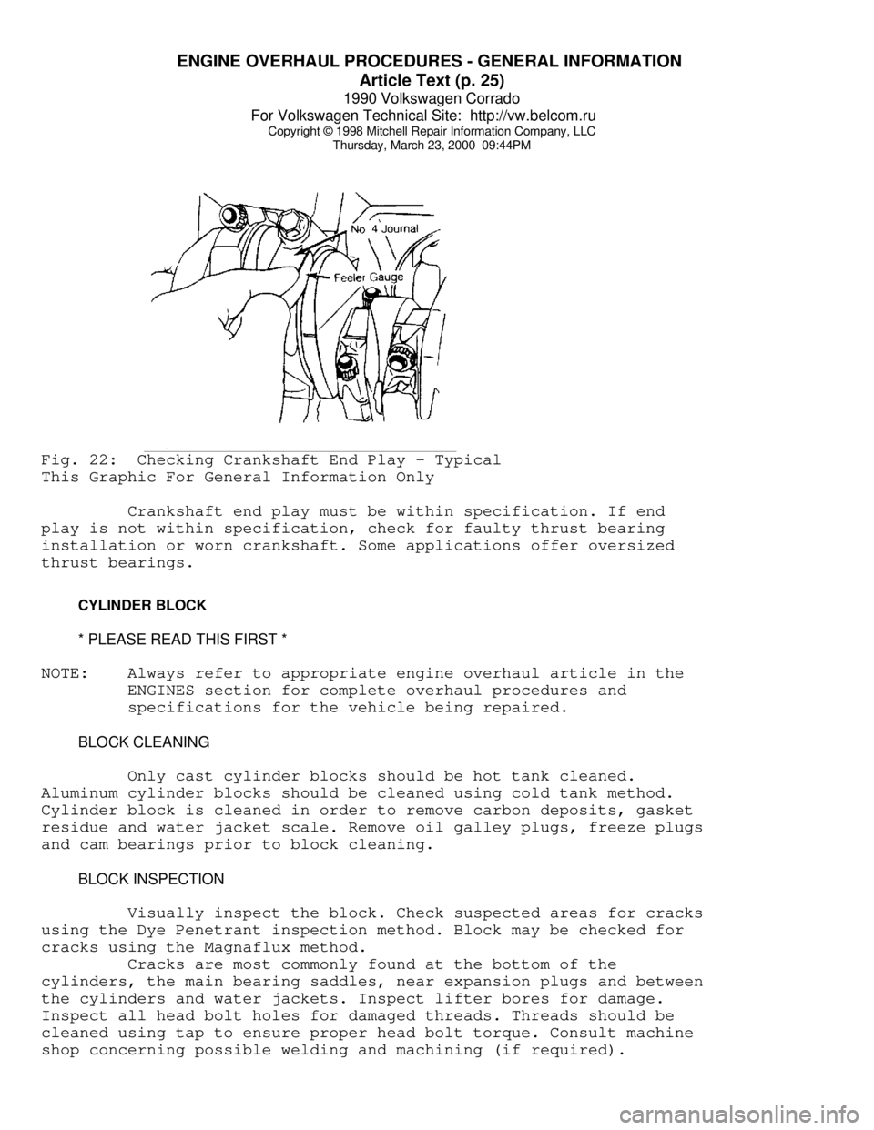
Thursday, March 23, 2000 09:44PMFig. 22: Checking Crankshaft End Play - Typical
This Graphic For General Information Only
Crankshaft end play must be within specification. If end
play is not within specification, check for faulty thrust bearing
installation or worn crankshaft. Some applications offer oversized
thrust bearings.
CYLINDER BLOCK
* PLEASE READ THIS FIRST *
NOTE: Always refer to appropriate engine overhaul article in the
ENGINES section for complete overhaul procedures and
specifications for the vehicle being repaired.
BLOCK CLEANING
Only cast cylinder blocks should be hot tank cleaned.
Aluminum cylinder blocks should be cleaned using cold tank method.
Cylinder block is cleaned in order to remove carbon deposits, gasket
residue and water jacket scale. Remove oil galley plugs, freeze plugs
and cam bearings prior to block cleaning.
BLOCK INSPECTION
Visually inspect the block. Check suspected areas for cracks
using the Dye Penetrant inspection method. Block may be checked for
cracks using the Magnaflux method.
Cracks are most commonly found at the bottom of the
cylinders, the main bearing saddles, near expansion plugs and between
the cylinders and water jackets. Inspect lifter bores for damage.
Inspect all head bolt holes for damaged threads. Threads should be
cleaned using tap to ensure proper head bolt torque. Consult machine
shop concerning possible welding and machining (if required).
Page 535 of 906

ENGINE OVERHAUL PROCEDURES - GENERAL INFORMATION
Article Text (p. 26)
1990 Volkswagen Corrado
For Volkswagen Technical Site: http://vw.belcom.ru
Copyright © 1998 Mitchell Repair Information Company, LLC
Thursday, March 23, 2000 09:44PM
CYLINDER BORE INSPECTION
Inspect the bore for scuffing or roughness. Cylinder bore
is dimensionally checked for out-of-round and taper using dial bore
gauge. For determining out-of-round, measure cylinder parallel and
perpendicular to the block centerline. Difference in the 2 readings
is the bore out-of-round. Cylinder bore must be checked at top, middle
and bottom of piston travel area.
Bore taper is obtained by measuring bore at the top and
bottom. If wear has exceeded allowable limits, block must be honed
or bored to next available oversize piston dimension.
CYLINDER HONING
Cylinder must be properly honed to allow new piston rings to
properly seat. Cross-hatching at correct angle and depth is critical
to lubrication of cylinder walls and pistons.
A flexible drive hone and power drill are commonly used.
Drive hone must be lubricated during operation. Mix equal parts of
kerosene and SAE 20w engine oil for lubrication.
Apply lubrication to cylinder wall. Operate cylinder hone
from top to bottom of cylinder using even strokes to produce 45 degree
cross-hatch pattern on the cylinder wall. DO NOT allow cylinder hone
to extend below cylinder during operation.
Recheck bore dimension after final honing. Wash cylinder
wall with hot soapy water to remove abrasive particles. Blow dry with
compressed air. Coat cleaned cylinder walls with lubricating oil.
DECK WARPAGE
Check deck for damage or warped head sealing surface. Place
a straightedge across gasket surface of the deck. Using feeler gauge,
measure clearance at center of straightedge. Measure across width and
length of cylinder block at several points.
If warpage exceeds specifications, deck must be resurfaced.
If warpage exceeds manufacturer's maximum tolerance for material
removal, replace block.
DECK HEIGHT
Distance from the crankshaft centerline to the block
deck is termed the deck height. Measure and record front and rear main
journals of crankshaft. To compute this distance, install crankshaft
and retain with center main bearing and cap only. Measure distance
from the crankshaft journal to the block deck, parallel to the
cylinder centerline.
Add one half of the main bearing journal diameter to distance
from crankshaft journal to block deck. This dimension should be
checked at front and rear of cylinder block. Both readings should be
the same.
If difference exceeds specifications, cylinder block must be
repaired or replaced. Deck height and warpage should be corrected at
Page 536 of 906

ENGINE OVERHAUL PROCEDURES - GENERAL INFORMATION
Article Text (p. 27)
1990 Volkswagen Corrado
For Volkswagen Technical Site: http://vw.belcom.ru
Copyright © 1998 Mitchell Repair Information Company, LLC
Thursday, March 23, 2000 09:44PM
the same time.
MAIN BEARING BORE & ALIGNMENT
For checking main bearing bore, remove all bearings from
cylinder block and main bearing caps. Install main bearing caps in
original location. Tighten bolts to specification. Using inside
micrometer, measure main bearing bore in 2 areas 90 degrees apart.
Determine bore size and out-of-round. If diameter is not within
specification, block must be align-bored.
For checking alignment, place a straightedge along centerline
of main bearing saddles. Check for clearance between straightedge and
main bearing saddles. Block must be align-bored if clearance is
present.
EXPANSION PLUG REMOVAL & INSTALLATION
Removal
Drill a hole in the center of expansion plug. Remove with
screwdriver or punch. Use care not to damage sealing surface.
Installation
Ensure sealing surface is free of burrs. Coat expansion plug
with sealer. Use a wooden dowel or pipe of slightly smaller diameter,
install expansion plug. Ensure expansion plug is evenly located.
OIL GALLERY PLUG REMOVAL & INSTALLATION
Removal
Remove threaded oil gallery plugs using the appropriate
wrench. Soft, press-in plugs are removed by drilling into plug and
installing a sheet metal screw. Remove plug with slide hammer or
pliers.
Installation
Ensure threads or sealing surface is clean. Coat threaded oil
gallery plugs with sealer and install. Replacement soft press-in plugs
are driven in place with a hammer and drift.
CAMSHAFT
* PLEASE READ THIS FIRST *
NOTE: Always refer to appropriate engine overhaul article in the
ENGINES section for complete overhaul procedures and
specifications for the vehicle being repaired.
CLEANING & INSPECTION
Clean camshaft with solvent. Ensure all oil passages are
clear. Inspect cam lobes and bearing journals for pitting, flaking or
scoring. Using micrometer, measure bearing journal O.D.
Page 545 of 906

ENGINE OVERHAUL PROCEDURES - GENERAL INFORMATION
Article Text (p. 36)
1990 Volkswagen Corrado
For Volkswagen Technical Site: http://vw.belcom.ru
Copyright © 1998 Mitchell Repair Information Company, LLC
Thursday, March 23, 2000 09:44PM
to ensure correct amount of oil has filled crankcase. Check oil level
while pre-oiling.
If pressure oiler is not available, disconnect ignition
system. Remove oil pressure sending unit and replace with oil pressure
test gauge. Using starter motor, rotate engine starter until gauge
shows normal oil pressure for several seconds. DO NOT crank engine
for more than 30 seconds to avoid starter motor damage.
Ensure oil pressure has reached the most distant point from
the oil pump. Reinstall oil pressure sending unit. Reconnect ignition
system.
INITIAL START-UP
Start the engine and operate engine at low speed while
checking for coolant, fuel and oil leaks. Stop engine. Recheck coolant
and oil level. Adjust if necessary.
CAMSHAFT
Break-in procedure is required when a new or reground
camshaft has been installed. Operate and maintain engine speed between
1500-2500 RPM for approximately 30 minutes. Procedure may vary due to
manufacturers recommendations.
PISTON RINGS
Piston rings require a break-in procedure to ensure seating
of rings to cylinder walls. Serious damage may occur to rings if
correct procedures are not followed.
Extremely high piston ring temperatures are produced obtained
during break-in process. If rings are exposed to excessively high RPM
or high cylinder pressures, ring damage can occur. Follow piston ring
manufacturer's recommended break-in procedure.
FINAL ADJUSTMENTS
Check or adjust ignition timing and dwell (if applicable).
Adjust valves (if necessary). Adjust carburetion or injection idle
speed and mixture. Retighten cylinder heads (if required). If
cylinder head or block is aluminum, retighten bolts when engine is
cold. Follow the engine manufacturer's recommended break-in procedure
and maintenance schedule for new engines.
NOTE: Some manufacturer's require that head bolts be retightened
after specified amount of operation. This must be done to
prevent head gasket failure.
END OF ARTICLE
Page 546 of 906

F - BASIC TESTING
Article Text
1990 Volkswagen Corrado
For Volkswagen Technical Site: http://vw.belcom.ru
Copyright © 1998 Mitchell Repair Information Company, LLC
Thursday, March 23, 2000 09:44PM
ARTICLE BEGINNING
1990 ENGINE PERFORMANCE
Volkswagen Basic Diagnostic Procedures
Cabriolet, Corrado, Fox, Golf GL/GTI, Jetta, Vanagon
INTRODUCTION
The following diagnostic steps will help prevent overlooking
a simple problem. This is also where to begin diagnosis for a no start
condition.
The first step in diagnosing any driveability problem is
verifying the customer's complaint with a test drive under the
conditions the problem reportedly occurred.
Perform a careful and complete visual inspection. Most engine
control problems result from mechanical breakdowns, poor electrical
connections or damaged/misrouted vacuum hoses. Before condemning the
computerized system, perform each test listed in this article.
NOTE: Perform all voltage tests with a Digital Volt-Ohmmeter
(DVOM) with a minimum 10-megohm input impedance, unless
stated otherwise in test procedure.
VISUAL INSPECTION
Visually inspect all electrical wiring, looking for chafed,
stretched, cut or pinched wiring. Ensure electrical connectors fit
tightly and are not corroded. Ensure vacuum hoses are properly routed
and are not pinched or cut. See M - VACUUM DIAGRAMS article to verify
routing and connections (if necessary). Inspect air induction system
for possible vacuum leaks.
MECHANICAL INSPECTION
COMPRESSION
Check engine mechanical condition with a compression gauge,
vacuum gauge, or an engine analyzer. See engine analyzer manual for
specific instructions.
DO NOT use ignition switch during compression tests on fuel
injected vehicles. Use a remote starter to crank engine. Fuel
injectors on many models are triggered by ignition switch during
cranking mode, which can create a fire hazard or contaminate the
engine's oiling system.
EXHAUST SYSTEM BACKPRESSURE
The exhaust system can be checked with a vacuum or pressure
gauge. Remove O2 sensor or air injection check valve (if equipped).
Connect a 1-10 psi pressure gauge and run engine at 2500 RPM. If
Page 550 of 906

F - BASIC TESTING
Article Text (p. 5)
1990 Volkswagen Corrado
For Volkswagen Technical Site: http://vw.belcom.ru
Copyright © 1998 Mitchell Repair Information Company, LLC
Thursday, March 23, 2000 09:44PM
to OFF position.
(2) - With pressure regulator vacuum hose disconnected, pressure
should be 36 psi (2.5 kg/cmý).
ÄÄÄÄÄÄÄÄÄÄÄÄÄÄÄÄÄÄÄÄÄÄÄÄÄÄÄÄÄÄÄÄÄÄÄÄÄÄÄÄÄÄÄÄÄÄÄÄÄÄÄÄÄÄÄÄÄÄÄÄÄÄÄÄÄÄÄÄÄÄ TRANSFER PUMP CHECK
TRANSFER PUMP FUEL VOLUME CHECK
1) Turn ignition off. To check transfer pump (in tank),
remove rear seat. Remove fuel sending unit access cover. Disconnect
ignition coil secondary wire and jumper to ground. With transmission
in neutral, crank engine for a 3-4 seconds. While the starter is
turning and for a few seconds afterwards, an audible sound should be
heard at the pump. If not, proceed to step 2).
2) Activate fuel pumps by removing fuel pump relay and
attaching jumper wire between terminals No. 30 battery voltage and No.
87 output to fuel pumps. Terminal identification is molded on
fuse/relay panel. If pump does not operate, remove transfer pump
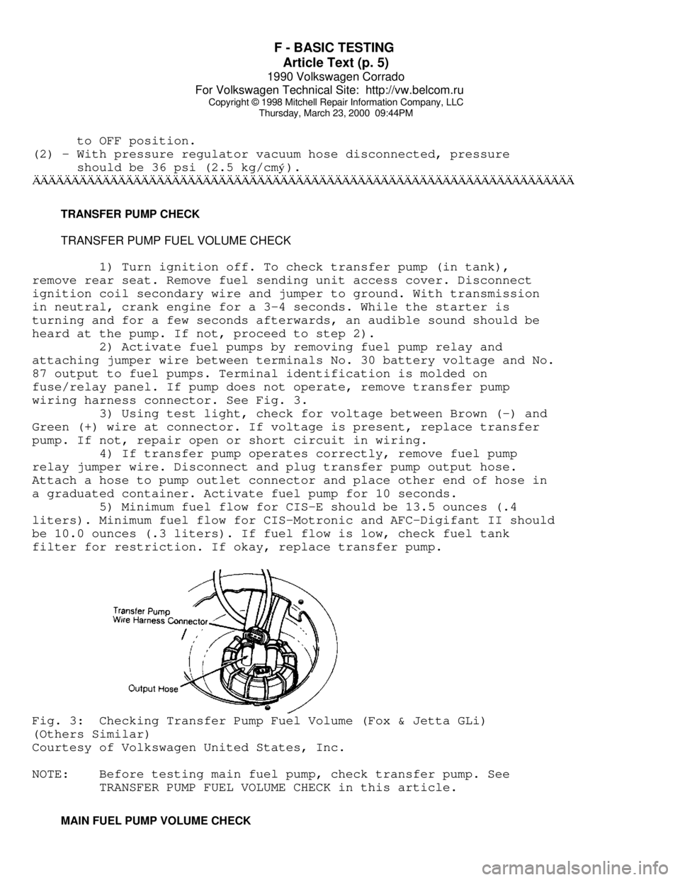
wiring harness connector. See Fig. 3.
3) Using test light, check for voltage between Brown (-) and
Green (+) wire at connector. If voltage is present, replace transfer
pump. If not, repair open or short circuit in wiring.
4) If transfer pump operates correctly, remove fuel pump
relay jumper wire. Disconnect and plug transfer pump output hose.
Attach a hose to pump outlet connector and place other end of hose in
a graduated container. Activate fuel pump for 10 seconds.
5) Minimum fuel flow for CIS-E should be 13.5 ounces (.4
liters). Minimum fuel flow for CIS-Motronic and AFC-Digifant II should
be 10.0 ounces (.3 liters). If fuel flow is low, check fuel tank
filter for restriction. If okay, replace transfer pump.Fig. 3: Checking Transfer Pump Fuel Volume (Fox & Jetta GLi)
(Others Similar)
Courtesy of Volkswagen United States, Inc.
NOTE: Before testing main fuel pump, check transfer pump. See
TRANSFER PUMP FUEL VOLUME CHECK in this article.
MAIN FUEL PUMP VOLUME CHECK
Page 552 of 906

F - BASIC TESTING
Article Text (p. 7)
1990 Volkswagen Corrado
For Volkswagen Technical Site: http://vw.belcom.ru
Copyright © 1998 Mitchell Repair Information Company, LLC
Thursday, March 23, 2000 09:44PM
11 .......................................... 1.1 (.520)
12 .......................................... 1.4 (.675)
Jetta GLi
10 .......................................... 1.0 (.460)
11 .......................................... 1.3 (.620)
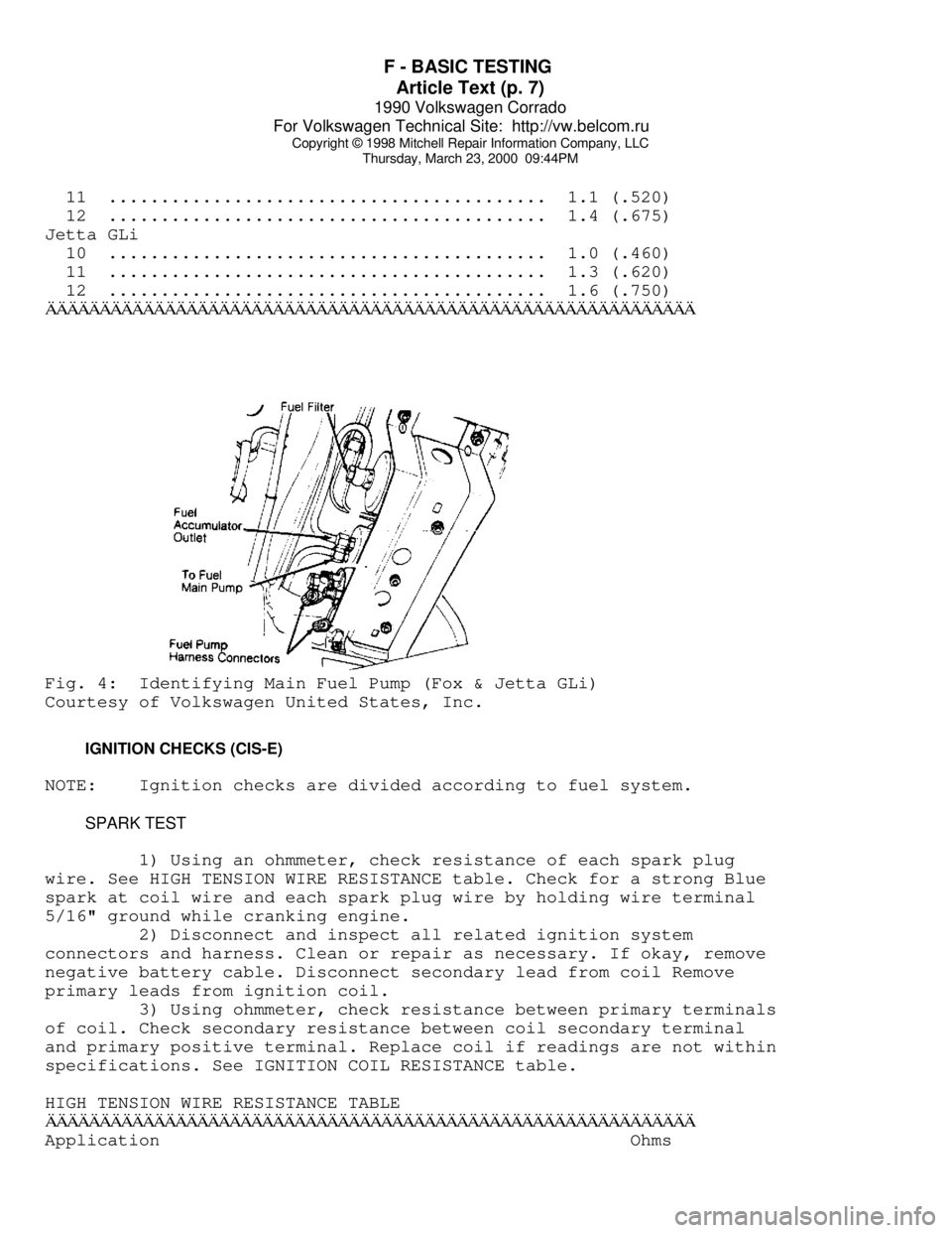
12 .......................................... 1.6 (.750)ÄÄÄÄÄÄÄÄÄÄÄÄÄÄÄÄÄÄÄÄÄÄÄÄÄÄÄÄÄÄÄÄÄÄÄÄÄÄÄÄÄÄÄÄÄÄÄÄÄÄÄÄÄÄÄÄÄÄÄÄFig. 4: Identifying Main Fuel Pump (Fox & Jetta GLi)
Courtesy of Volkswagen United States, Inc.
IGNITION CHECKS (CIS-E)
NOTE: Ignition checks are divided according to fuel system.
SPARK TEST
1) Using an ohmmeter, check resistance of each spark plug
wire. See HIGH TENSION WIRE RESISTANCE table. Check for a strong Blue
spark at coil wire and each spark plug wire by holding wire terminal
5/16" ground while cranking engine.
2) Disconnect and inspect all related ignition system
connectors and harness. Clean or repair as necessary. If okay, remove
negative battery cable. Disconnect secondary lead from coil Remove
primary leads from ignition coil.
3) Using ohmmeter, check resistance between primary terminals
of coil. Check secondary resistance between coil secondary terminal
and primary positive terminal. Replace coil if readings are not within
specifications. See IGNITION COIL RESISTANCE table.
HIGH TENSION WIRE RESISTANCE TABLE
ÄÄÄÄÄÄÄÄÄÄÄÄÄÄÄÄÄÄÄÄÄÄÄÄÄÄÄÄÄÄÄÄÄÄÄÄÄÄÄÄÄÄÄÄÄÄÄÄÄÄÄÄÄÄÄÄÄÄÄÄApplication Ohms
Page 553 of 906

F - BASIC TESTING
Article Text (p. 8)
1990 Volkswagen Corrado
For Volkswagen Technical Site: http://vw.belcom.ru
Copyright © 1998 Mitchell Repair Information Company, LLC
Thursday, March 23, 2000 09:44PM
Fox
Coil Wire With Connectors .................... 1600-2400
Spark Plug Wire With Connectors .............. 4800-7200
Spark Plug Connector ......................... 4000-6000
Suppressor .................................... 800-1200ÄÄÄÄÄÄÄÄÄÄÄÄÄÄÄÄÄÄÄÄÄÄÄÄÄÄÄÄÄÄÄÄÄÄÄÄÄÄÄÄÄÄÄÄÄÄÄÄÄÄÄÄÄÄÄÄÄÄÄÄ IGNITION COIL RESISTANCE TABLE
IGNITION COIL RESISTANCE TABLE - Ohms @ 68
øF (20øC)
ÄÄÄÄÄÄÄÄÄÄÄÄÄÄÄÄÄÄÄÄÄÄÄÄÄÄÄÄÄÄÄÄÄÄÄÄÄÄÄÄÄÄÄÄÄÄÄÄÄÄÄÄÄÄÄÄÄÄÄÄApplication Primary Secondary
Jetta GLi 2.0L ......... .60-.70 ............. 6500-8500
All Other Models ....... .52-.76 ............. 2400-3500
ÄÄÄÄÄÄÄÄÄÄÄÄÄÄÄÄÄÄÄÄÄÄÄÄÄÄÄÄÄÄÄÄÄÄÄÄÄÄÄÄÄÄÄÄÄÄÄÄÄÄÄÄÄÄÄÄÄÄÄÄ DISTRIBUTOR
HALL EFFECT SENDER
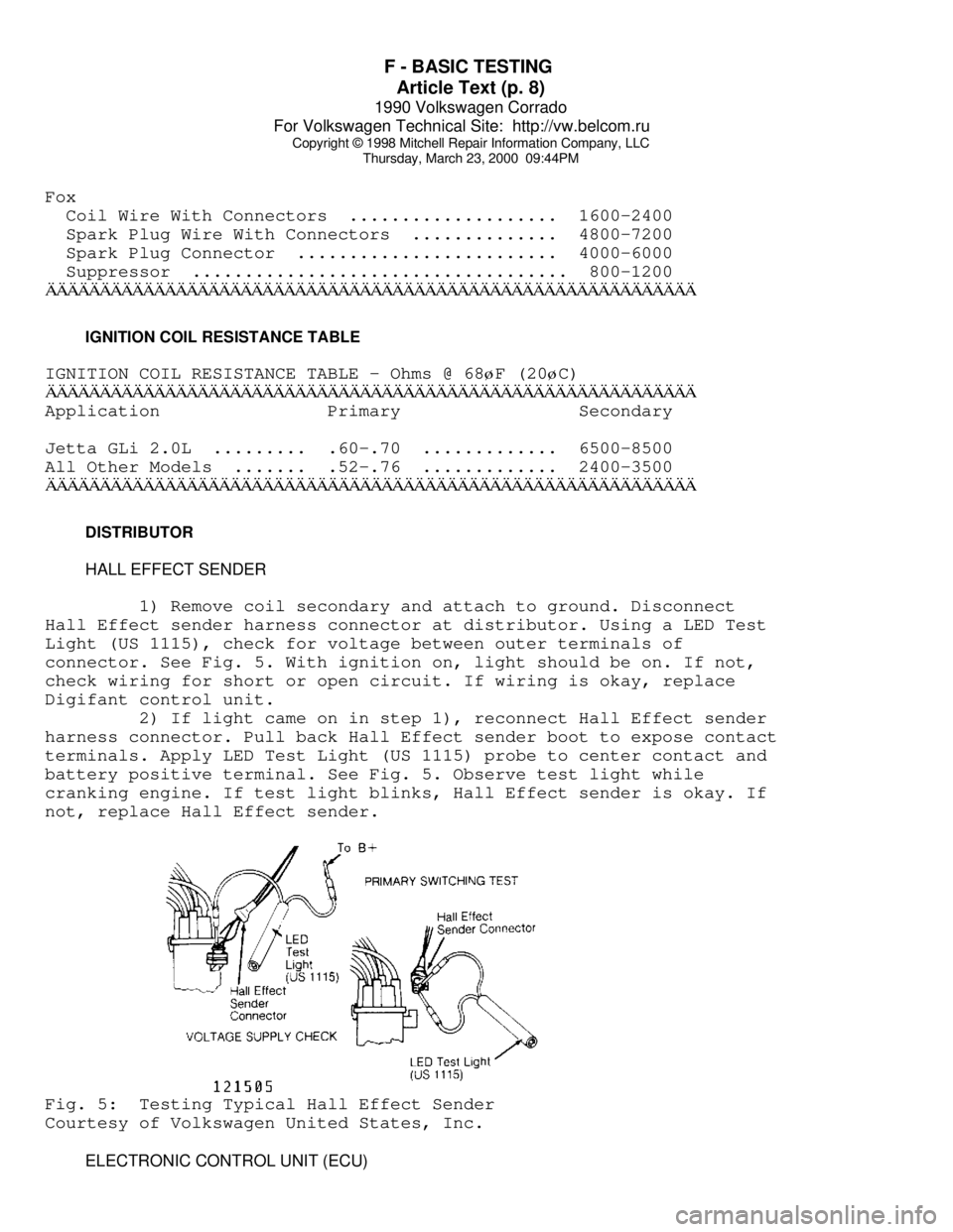
1) Remove coil secondary and attach to ground. Disconnect
Hall Effect sender harness connector at distributor. Using a LED Test
Light (US 1115), check for voltage between outer terminals of
connector. See Fig. 5. With ignition on, light should be on. If not,
check wiring for short or open circuit. If wiring is okay, replace
Digifant control unit.
2) If light came on in step 1), reconnect Hall Effect sender
harness connector. Pull back Hall Effect sender boot to expose contact
terminals. Apply LED Test Light (US 1115) probe to center contact and
battery positive terminal. See Fig. 5. Observe test light while
cranking engine. If test light blinks, Hall Effect sender is okay. If
not, replace Hall Effect sender.Fig. 5: Testing Typical Hall Effect Sender
Courtesy of Volkswagen United States, Inc.
ELECTRONIC CONTROL UNIT (ECU)