1990 VOLKSWAGEN CORRADO check oil
[x] Cancel search: check oilPage 554 of 906

F - BASIC TESTING
Article Text (p. 9)
1990 Volkswagen Corrado
For Volkswagen Technical Site: http://vw.belcom.ru
Copyright © 1998 Mitchell Repair Information Company, LLC
Thursday, March 23, 2000 09:44PM
1) Perform SPARK TEST check. If secondary spark is present,
ignition control unit is okay. If not, turn ignition off. Disconnect
ignition control unit wire harness connector. Turn ignition on. Using
a voltmeter, measure voltage between terminal No. 2 (-) and terminal
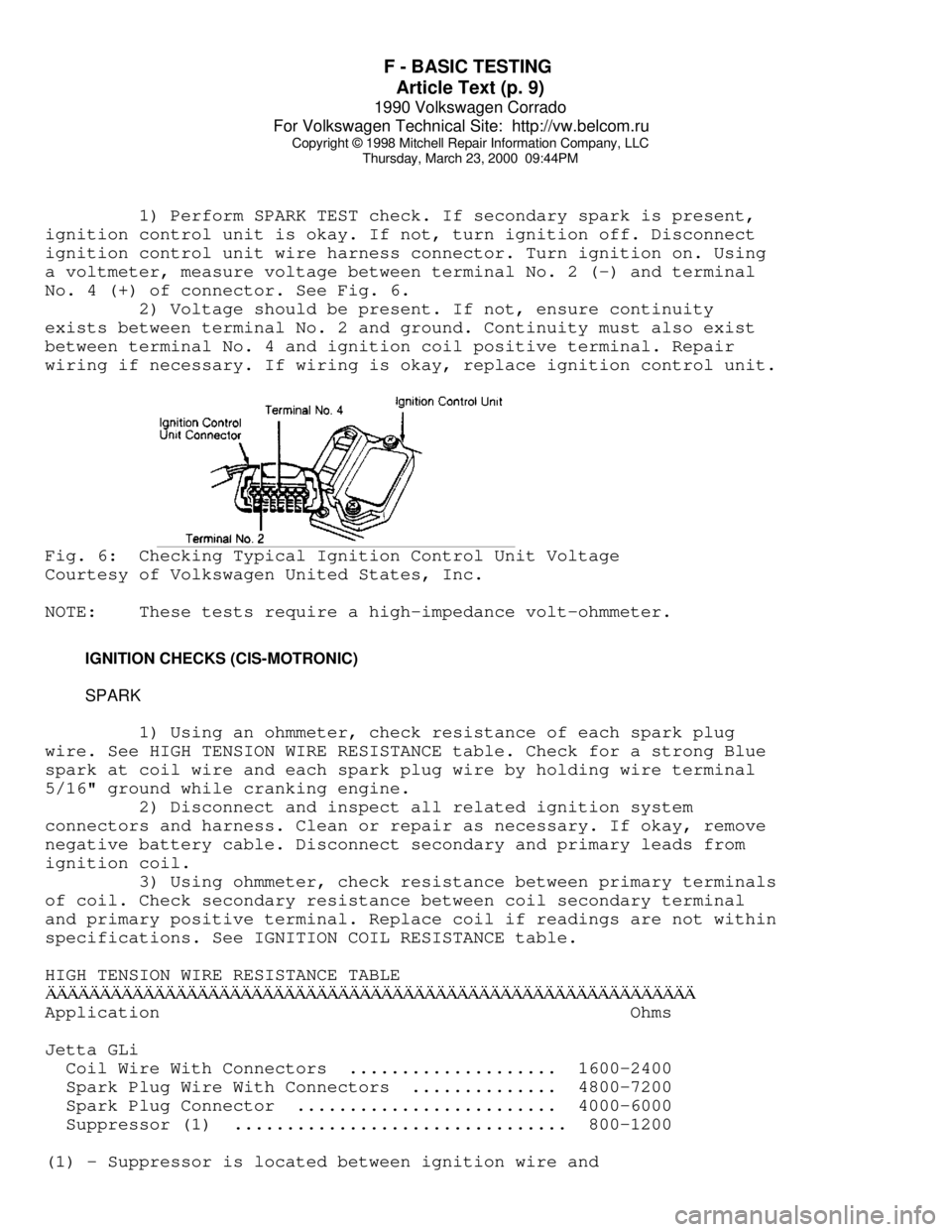
No. 4 (+) of connector. See Fig. 6.
2) Voltage should be present. If not, ensure continuity
exists between terminal No. 2 and ground. Continuity must also exist
between terminal No. 4 and ignition coil positive terminal. Repair
wiring if necessary. If wiring is okay, replace ignition control unit.Fig. 6: Checking Typical Ignition Control Unit Voltage
Courtesy of Volkswagen United States, Inc.
NOTE: These tests require a high-impedance volt-ohmmeter.
IGNITION CHECKS (CIS-MOTRONIC)
SPARK
1) Using an ohmmeter, check resistance of each spark plug
wire. See HIGH TENSION WIRE RESISTANCE table. Check for a strong Blue
spark at coil wire and each spark plug wire by holding wire terminal
5/16" ground while cranking engine.
2) Disconnect and inspect all related ignition system
connectors and harness. Clean or repair as necessary. If okay, remove
negative battery cable. Disconnect secondary and primary leads from
ignition coil.
3) Using ohmmeter, check resistance between primary terminals
of coil. Check secondary resistance between coil secondary terminal
and primary positive terminal. Replace coil if readings are not within
specifications. See IGNITION COIL RESISTANCE table.
HIGH TENSION WIRE RESISTANCE TABLEÄÄÄÄÄÄÄÄÄÄÄÄÄÄÄÄÄÄÄÄÄÄÄÄÄÄÄÄÄÄÄÄÄÄÄÄÄÄÄÄÄÄÄÄÄÄÄÄÄÄÄÄÄÄÄÄÄÄÄÄApplication Ohms
Jetta GLi
Coil Wire With Connectors .................... 1600-2400
Spark Plug Wire With Connectors .............. 4800-7200
Spark Plug Connector ......................... 4000-6000
Suppressor (1) ................................ 800-1200
(1) - Suppressor is located between ignition wire and
Page 555 of 906

F - BASIC TESTING
Article Text (p. 10)
1990 Volkswagen Corrado
For Volkswagen Technical Site: http://vw.belcom.ru
Copyright © 1998 Mitchell Repair Information Company, LLC
Thursday, March 23, 2000 09:44PM
distributor cap.ÄÄÄÄÄÄÄÄÄÄÄÄÄÄÄÄÄÄÄÄÄÄÄÄÄÄÄÄÄÄÄÄÄÄÄÄÄÄÄÄÄÄÄÄÄÄÄÄÄÄÄÄÄÄÄÄÄÄÄÄ HALL EFFECT SENDER & COIL POWER STAGE
The Hall Effect sender and coil power stage should be tested
if there is no spark at the spark plugs when tested. These tests also
check the CIS-Motronic ECU response to the Hall Effect sender signal.
Ensure SPARK and IGNITION COIL tests are performed first.
VOLTAGE SUPPLY & GROUND TO POWER STAGE
1) With ignition off, disconnect the coil power stage harness
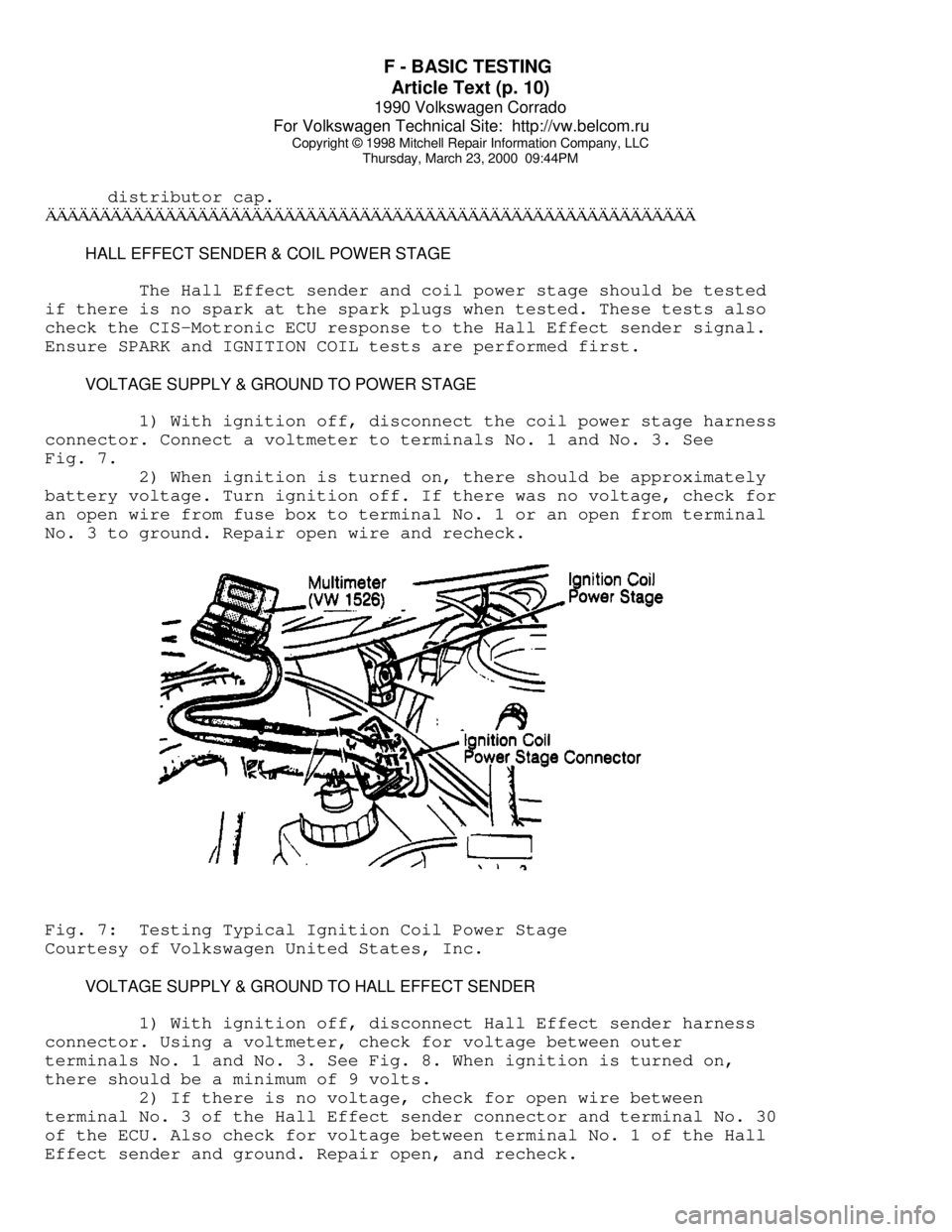
connector. Connect a voltmeter to terminals No. 1 and No. 3. See
Fig. 7.
2) When ignition is turned on, there should be approximately
battery voltage. Turn ignition off. If there was no voltage, check for
an open wire from fuse box to terminal No. 1 or an open from terminal
No. 3 to ground. Repair open wire and recheck.Fig. 7: Testing Typical Ignition Coil Power Stage
Courtesy of Volkswagen United States, Inc.
VOLTAGE SUPPLY & GROUND TO HALL EFFECT SENDER
1) With ignition off, disconnect Hall Effect sender harness
connector. Using a voltmeter, check for voltage between outer
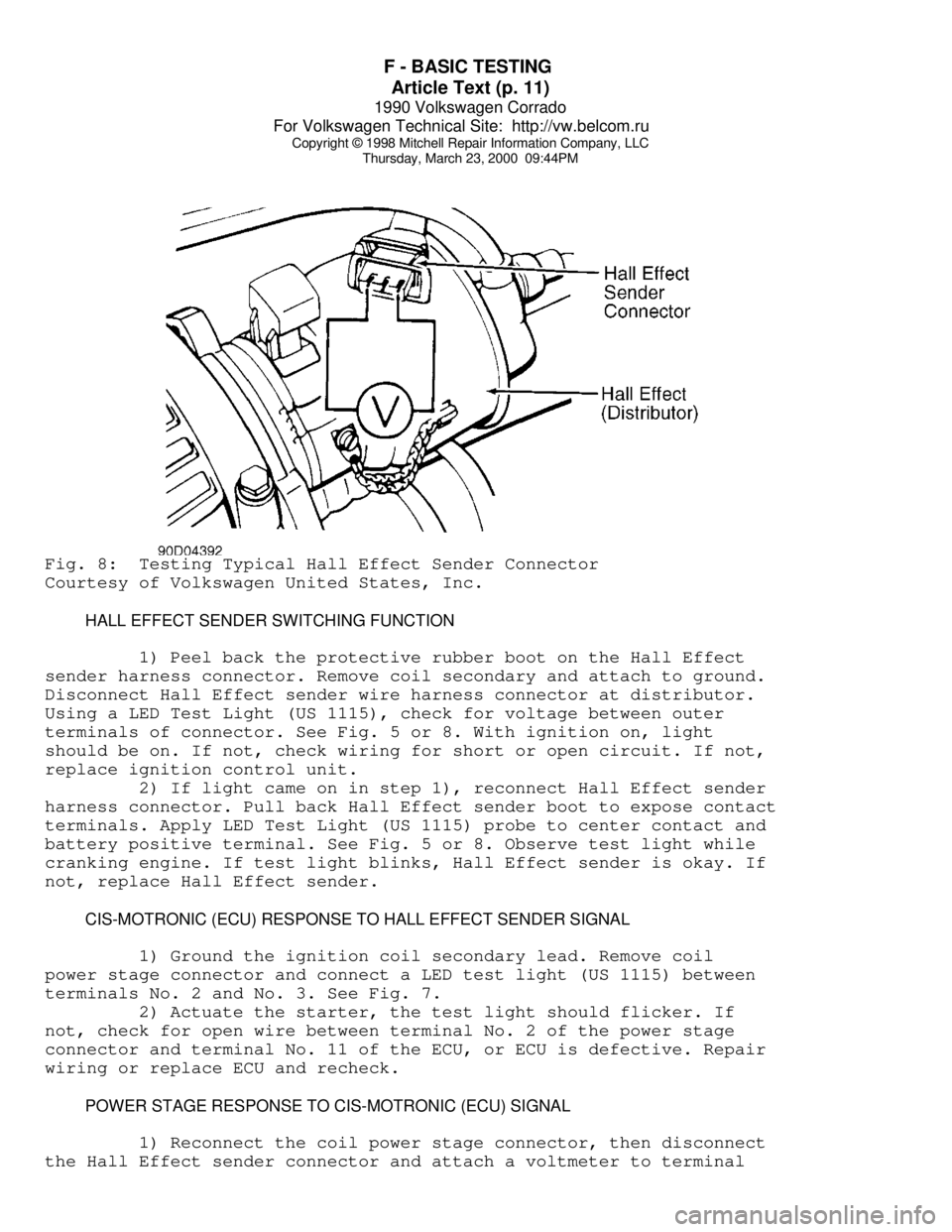
terminals No. 1 and No. 3. See Fig. 8. When ignition is turned on,
there should be a minimum of 9 volts.
2) If there is no voltage, check for open wire between
terminal No. 3 of the Hall Effect sender connector and terminal No. 30
of the ECU. Also check for voltage between terminal No. 1 of the Hall
Effect sender and ground. Repair open, and recheck.
Page 556 of 906

F - BASIC TESTING
Article Text (p. 11)
1990 Volkswagen Corrado
For Volkswagen Technical Site: http://vw.belcom.ru
Copyright © 1998 Mitchell Repair Information Company, LLC
Thursday, March 23, 2000 09:44PMFig. 8: Testing Typical Hall Effect Sender Connector
Courtesy of Volkswagen United States, Inc.
HALL EFFECT SENDER SWITCHING FUNCTION
1) Peel back the protective rubber boot on the Hall Effect
sender harness connector. Remove coil secondary and attach to ground.
Disconnect Hall Effect sender wire harness connector at distributor.
Using a LED Test Light (US 1115), check for voltage between outer
terminals of connector. See Fig. 5 or 8. With ignition on, light
should be on. If not, check wiring for short or open circuit. If not,
replace ignition control unit.
2) If light came on in step 1), reconnect Hall Effect sender
harness connector. Pull back Hall Effect sender boot to expose contact
terminals. Apply LED Test Light (US 1115) probe to center contact and
battery positive terminal. See Fig. 5 or 8. Observe test light while
cranking engine. If test light blinks, Hall Effect sender is okay. If
not, replace Hall Effect sender.
CIS-MOTRONIC (ECU) RESPONSE TO HALL EFFECT SENDER SIGNAL
1) Ground the ignition coil secondary lead. Remove coil
power stage connector and connect a LED test light (US 1115) between
terminals No. 2 and No. 3. See Fig. 7.
2) Actuate the starter, the test light should flicker. If
not, check for open wire between terminal No. 2 of the power stage
connector and terminal No. 11 of the ECU, or ECU is defective. Repair
wiring or replace ECU and recheck.
POWER STAGE RESPONSE TO CIS-MOTRONIC (ECU) SIGNAL
1) Reconnect the coil power stage connector, then disconnect
the Hall Effect sender connector and attach a voltmeter to terminal
Page 557 of 906

F - BASIC TESTING
Article Text (p. 12)
1990 Volkswagen Corrado
For Volkswagen Technical Site: http://vw.belcom.ru
Copyright © 1998 Mitchell Repair Information Company, LLC
Thursday, March 23, 2000 09:44PM
No. 1 and No. 15 of the coil.
2) Turn the ignition on, using a jumper wire, briefly connect
the center terminal of the Hall Effect sender connector to ground. The
voltage should briefly increase to at least 2 volts then drop to zero.
If not, either the ECU or coil power stage are defective.
IGNITION CHECKS (AFC-DIGIFANT II)
SPARK TEST
1) Using an ohmmeter, check resistance of each spark plug
wire. See HIGH TENSION WIRE RESISTANCE table. Check for a strong Blue
spark at coil wire and each spark plug wire by holding wire terminal
5/16" ground while cranking engine.
2) Disconnect and inspect all related ignition system
connectors and harness. Clean or repair as necessary. If okay, remove
negative battery cable. Disconnect secondary and primary leads from
ignition coil.
3) Using ohmmeter, check resistance between primary terminals
of coil. Check secondary resistance between coil secondary terminal
and primary positive terminal. Replace coil if readings are not within
specifications. See IGNITION COIL RESISTANCE table.
HIGH TENSION WIRE RESISTANCE TABLEÄÄÄÄÄÄÄÄÄÄÄÄÄÄÄÄÄÄÄÄÄÄÄÄÄÄÄÄÄÄÄÄÄÄÄÄÄÄÄÄÄÄÄÄÄÄÄÄÄÄÄÄÄÄÄÄÄÄÄÄApplication Ohms
Vanagon
Coil Wire With Connectors ................... 1200-2800
Spark Plug Wire/Connector ................... 4600-7400
Spark Plug Connector ........................ 4000-6000
Suppressor (1) ............................... 600-1400
All Other Models
Coil Wire Only .................................... (1)
Coil Wire With Connector .................... 1600-2400
Spark Plug Wire/ Connector .................. 4000-6000
Suppressor (2) ............................... 600-1400
(1) - Check for continuity.
(2) - Suppressor is located between ignition wire and
distributor cap.
ÄÄÄÄÄÄÄÄÄÄÄÄÄÄÄÄÄÄÄÄÄÄÄÄÄÄÄÄÄÄÄÄÄÄÄÄÄÄÄÄÄÄÄÄÄÄÄÄÄÄÄÄÄÄÄÄÄÄÄÄ IGNITION COIL
IGNITION COIL RESISTANCE TABLE - Ohms @ 68
øF (20øC)
ÄÄÄÄÄÄÄÄÄÄÄÄÄÄÄÄÄÄÄÄÄÄÄÄÄÄÄÄÄÄÄÄÄÄÄÄÄÄÄÄÄÄÄÄÄÄÄÄÄÄÄÄÄÄÄÄÄÄÄÄApplication Primary Secondary
Jetta GLi 2.0L ......... .60-.70 ............. 6900-8500
All Other Models ....... .52-.76 ............. 2400-3500
ÄÄÄÄÄÄÄÄÄÄÄÄÄÄÄÄÄÄÄÄÄÄÄÄÄÄÄÄÄÄÄÄÄÄÄÄÄÄÄÄÄÄÄÄÄÄÄÄÄÄÄÄÄÄÄÄÄÄÄÄ
Page 558 of 906

F - BASIC TESTING
Article Text (p. 13)
1990 Volkswagen Corrado
For Volkswagen Technical Site: http://vw.belcom.ru
Copyright © 1998 Mitchell Repair Information Company, LLC
Thursday, March 23, 2000 09:44PM
DISTRIBUTOR
HALL EFFECT SENDER
1) Remove coil secondary and attach to ground. Disconnect
Hall Effect sender wire at the distributor. Using a LED Test Light (US
1115), check for voltage between outer terminals of connector. See
Fig. 5 or 8. With ignition on, light should be on. If not, check
wiring for short or open circuit. If wiring is okay, replace Digifant
control unit.
2) If light came on in step 1), reconnect Hall Effect sender
harness connector. Pull back Hall Effect sender boot to expose contact
terminals. Apply LED Test Light (US 1115) probe to center contact and
battery positive terminal. See Fig. 5. Observe test light while
cranking engine. If test light blinks, Hall Effect sender is okay. If
not, replace Hall Effect-sender.
IDLE SPEED, CO LEVEL & IGNITION TIMING
Ensure idle speed, CO level and base ignition timing are set
to specification. If necessary, see ON-VEHICLE ADJUSTMENTS article.
IDLE SPEED & CO LEVEL TABLEÄÄÄÄÄÄÄÄÄÄÄÄÄÄÄÄÄÄÄÄÄÄÄÄÄÄÄÄÄÄÄÄÄÄÄÄÄÄÄÄÄÄÄÄÄÄÄÄÄÄÄÄÄÄÄÄÄÄÄÄApplication Idle RPM CO Level %
All Models ............ 800-1000 .............. 0.3-1.2%
ÄÄÄÄÄÄÄÄÄÄÄÄÄÄÄÄÄÄÄÄÄÄÄÄÄÄÄÄÄÄÄÄÄÄÄÄÄÄÄÄÄÄÄÄÄÄÄÄÄÄÄÄÄÄÄÄÄÄÄÄIGNITION TIMING TABLE (Degrees BTDC @ RPM)
ÄÄÄÄÄÄÄÄÄÄÄÄÄÄÄÄÄÄÄÄÄÄÄÄÄÄÄÄÄÄÄÄÄÄÄÄÄÄÄÄÄÄÄÄÄÄÄÄÄÄÄÄÄÄÄÄÄÄÄÄApplication Checking Adjusting
1.8L ............... 4-8 @ 2250-2350 . 5-7 @ 2250-2350
2.0L ................ 4-8 @ 770-830 ...... 5-7 @ 770-830
2.1L (1) ........... 4-8 @ 2250-2350 . 5-7 @ 2250-2350
(1) - With coolant temperature sensor disconnected.
ÄÄÄÄÄÄÄÄÄÄÄÄÄÄÄÄÄÄÄÄÄÄÄÄÄÄÄÄÄÄÄÄÄÄÄÄÄÄÄÄÄÄÄÄÄÄÄÄÄÄÄÄÄÄÄÄÄÄÄÄ SUMMARY
If no faults were found while performing F - BASIC TESTING,
proceed to H - TESTS W/CODES article for diagnosis by symptom (i.e.,
ROUGH IDLE, NO START, etc.) or intermittent diagnostic procedures.
END OF ARTICLE
Page 575 of 906

H - TESTS W/O CODES
Article Text (p. 2)
1990 Volkswagen Corrado
For Volkswagen Technical Site: http://vw.belcom.ru
Copyright © 1998 Mitchell Repair Information Company, LLC
Thursday, March 23, 2000 09:45PM
WILL NOT START OR STARTS HARD COLD (CRANKS OKAY)
* Check ignition fuse (if equipped).
* Check fuel pump fuse and fuel pump relay.
* Verify air intake system is unrestricted.
* Ensure fuel system pressure and volume are correct.
* Check cold start valve and thermo time switch operation.
* Ensure airflow sensor plate is in rest position. Adjust as
necessary.
* Test coolant temperature sensor and wiring. Repair or replace
as required.
* Check for poor ignition ground (1.8L & 2.0L 16-valve engines).
* Check for poor quality or contaminated fuel.
* Check condensation (water) in fuel tank causing fuel pump to
freeze (cold climate).
* Check exhaust system for restriction.
* Test airflow meter. Replace if faulty.
* Ensure sufficient secondary spark is available.
* Check air induction system for cracks or restriction.
* Ensure vacuum hoses are not disconnected or damaged.
* Ensure fuel system residual pressure is correct.
* Ensure fuel injector operation is correct.
* Ensure EGR valve operation is correct and valve closes
completely (if equipped).
* Check for cracks or poor connections at throttle body.
* Ensure ignition and valve timing are correct.
* Check ignition coil primary connections and wiring harness.
* Ensure ignition coil resistance is within specification.
* Check air temperature sensor operation (if equipped).
* Ensure electrical harness and connectors are not broken or loose.
* Ensure ECU or ignition control unit has correct voltage supply
and is properly grounded.
* Ensure engine has sufficient compression.
* Inspect intake air components for leaking hoses, connections or
cracks. Repair as required.
WILL NOT START OR STARTS HARD HOT (CRANKS OKAY)
* Check ignition fuse (if equipped).
* Check fuel system fuse and fuel pump relay.
* Check for poor quality or contaminated fuel.
* Check condensation (water) in fuel tank causing fuel pump to
freeze (cold climate).
* Check exhaust system for restriction.
* Check cold start valve and thermo time switch operation.
* Check fuel system and control system pressure. Replace pressure
regulator if necessary.
* Check residual fuel pressure. Replace fuel pump check valve or
fuel accumulator as necessary.
* Check oxygen sensor system operation.
* Ensure airflow sensor plate is in rest position. Adjust as
Page 576 of 906

H - TESTS W/O CODES
Article Text (p. 3)
1990 Volkswagen Corrado
For Volkswagen Technical Site: http://vw.belcom.ru
Copyright © 1998 Mitchell Repair Information Company, LLC
Thursday, March 23, 2000 09:45PM
necessary.
* Ensure injector spray patterns and volume are correct. Replace
faulty injectors.
* Inspect fuel lines and connections for leaks.
* Check carbon canister solenoid valves (CIS-E Motronic).
* Test airflow meter. Replace if faulty.
* Ensure sufficient secondary spark is available.
* Check air induction system for cracks or restriction.
* Check airflow sensor plate rest position.
* Ensure vacuum hoses are not disconnected or damaged.
* Ensure EGR valve operation is correct and valve closes
completely (if equipped).
* Check for cracks or poor connections at throttle body.
* Ensure ignition and valve timing are correct.
* Check ignition coil primary connections and wiring harness.
* Ensure ignition coil resistance is within specification.
* Check air temperature sensor operation.
* Check coolant temperature sensor operation.
* Ensure electrical harness and connectors are not broken or loose.
* Ensure ECU or ignition control unit has correct voltage supply
and is properly grounded.
* Ensure engine has sufficient compression.
ENGINE STALLS OR IDLES ROUGH
* Check fuel system and control system pressure. Replace pressure
regulator if necessary.
* Check cold start valve for leaking (engine warm).
* Ensure injector spray patterns and volume are correct. Replace
faulty injectors.
* Test coolant temperature sensor and wiring. Repair or replace
as required.
* Inspect intake air components for leaking hoses, connections or
cracks. Repair as required.
* Ensure airflow sensor plate movement and rest position. Adjust
as necessary.
* Test idle switch and idle air stabilizer valve.
* Perform system electrical checks.
* Check airflow meter. Replace if faulty.
* Ensure idle RPM is correct.
* Check auxiliary air by-pass regulator.
* Check fuel injector electrical connections.
* Use stethoscope to verify fuel injectors are operating.
* Ensure sufficient secondary spark is available in all cylinders.
* Verify vacuum hose routing is correct and there are no
vacuum leaks.
* Check idle stabilizer operation.
* Check for EGR system malfunction (if equipped).
* Check O2 sensor operation.
* Check for distortion or cracks in fuel injector(s) plastic
connecting flange(s).
* Check for use of poor quality fuel containing insufficient
Page 588 of 906

I - SYSTEM/COMPONENT TESTS
Article Text
1990 Volkswagen Corrado
For Volkswagen Technical Site: http://vw.belcom.ru
Copyright © 1998 Mitchell Repair Information Company, LLC
Thursday, March 23, 2000 09:46PM
ARTICLE BEGINNING
1990 ENGINE PERFORMANCE
Systems & Component Testing
Volkswagen; Cabriolet, Corrado, Fox, Golf GL/GTI,
Jetta, Vanagon
INTRODUCTION
Before testing separate components or systems, perform
procedures in F - BASIC TESTING and H - TESTS W/O CODES articles.
NOTE: Testing individual components does not isolate shorts or
opens. Perform all voltage tests with a Digital
Volt-Ohmmeter (DVOM) with a minimum 10-megohm input
impedance, unless stated otherwise in test procedure. Use
ohmmeter to isolate wiring harness shorts or opens.
AIR INDUCTION SYSTEMS (SUPERCHARGER)
BOOST PRESSURE
1) Before checking supercharger boost pressure, ensure engine
idle speed is correct. See D - ADJUSTMENTS article. Ensure engine oil
temperature is 176øF (80øC). Check knock sensor operation. See KNOCK
SENSOR under IDLE CONTROL SYSTEM in this article.
2) Connect Pressure Gauge (VW1397) or equivalent to the
pressure regulator hose using adapter "T". Open pressure gauge check
valve to position "A" and start engine.
3) Remove harness connector from CO potentiometer and Blue
connector from temperature sensor (in front flange on cylinder head).
Accelerate to full throttle. Engine speed must increase periodically
then drop (surge). Watch pressure gauge, boost pressure must reach 8.7
psi (0.6 kg/cm
ý). If boost does not reach specification, check for
leaks in air system and correct by-pass valve setting. Check
supercharger.
COMPUTERIZED ENGINE CONTROLS
NOTE: For fuel system used on model being tested, see FUEL SYSTEM
APPLICATION table.
FUEL SYSTEM APPLICATION
ÄÄÄÄÄÄÄÄÄÄÄÄÄÄÄÄÄÄÄÄÄÄÄÄÄÄÄÄÄÄÄÄÄÄÄÄÄÄÄÄÄÄÄÄÄÄÄÄÄÄÄÄÄÄÄÄÄÄÄÄÄÄÄÄÄÄÄÄÄÄApplication Fuel System
Cabriolet, Corrado, Golf GL/GTI,
Jetta & Vanagon .................................. AFC-Digifant II
Fox .......................................................... CIS-E
Jetta GLi ............................................. CIS-Motronic