1990 VOLKSWAGEN CORRADO fuse diagram
[x] Cancel search: fuse diagramPage 589 of 906

I - SYSTEM/COMPONENT TESTS
Article Text (p. 2)
1990 Volkswagen Corrado
For Volkswagen Technical Site: http://vw.belcom.ru
Copyright © 1998 Mitchell Repair Information Company, LLC
Thursday, March 23, 2000 09:46PMÄÄÄÄÄÄÄÄÄÄÄÄÄÄÄÄÄÄÄÄÄÄÄÄÄÄÄÄÄÄÄÄÄÄÄÄÄÄÄÄÄÄÄÄÄÄÄÄÄÄÄÄÄÄÄÄÄÄÄÄÄÄÄÄÄÄÄÄÄÄ CONTROL UNIT (AFC-DIGIFANT II)
NOTE: Before checking ECU terminal voltages, check all terminals
and connections for looseness or presence of corrosion.
Repair as needed, before continuing.
GROUND CIRCUITS
Using Multimeter (US 1119), check resistance of ground
connections for ECU. Remove ECU connector. Check continuity to ground
on terminals No. 13 and 19. See L - WIRING DIAGRAMS for terminal
identification. Resistance should be zero ohms. If resistance is not
zero ohms, repair open or short in wiring.
POWER CIRCUITS
1) Turn ignition off. Disconnect ECU connector. Using a
voltmeter, turn ignition on and check for battery voltage between ECU
connector terminals No. 13 (negative) and No. 14 (positive). See L -
WIRING DIAGRAMS for terminal identification and wire colors. If
battery voltage is not present, repair wiring as required.
2) Check terminals No. 13 (negative) and No. 1 (positive) for
battery voltage. If battery voltage is not present, check fuse No. 18
on fuse block. If fuse is okay, check wiring from ECU connector to
fuse box for open.
CONTROL UNIT (CIS-E)
GROUND CIRCUITS
Using Multimeter (US 1119), check resistance of ground
circuits for ECU. Remove ECU connector. Check continuity to ground on
terminals No. 2 and No. 9. Resistance should be zero ohms. If
resistance is not zero ohms, repair open or short in wiring.
POWER CIRCUITS
Turn ignition off. Disconnect ECU connector. Using a
voltmeter, turn ignition on and check for battery voltage between ECU
connector terminals No. 2 (negative) and No. 1 (positive). See L -
WIRING DIAGRAMS for terminal identification and wire colors. If
battery voltage is not present, check fuse No. 23 on fuse block. If
fuse is okay, check CIS-E ECU connector to fuse box wiring for open.
CONTROL UNIT (CIS-MOTRONIC)
GROUND CIRCUITS
Using Multimeter (US 1119), check resistance of ground
Page 590 of 906
I - SYSTEM/COMPONENT TESTS
Article Text (p. 3)
1990 Volkswagen Corrado
For Volkswagen Technical Site: http://vw.belcom.ru
Copyright © 1998 Mitchell Repair Information Company, LLC
Thursday, March 23, 2000 09:46PM
circuits to ECU. The ECU engine ground is near ignition distributor.
Remove ECU connector. Check resistance to ground on terminal No. 35.
Resistance should be zero ohms. If resistance is not zero ohms, repair
open or short in wiring.
POWER CIRCUITS
Turn ignition off. Disconnect ECU connector. Using a
voltmeter, check terminals No. 12, 14, 19 and 34 for battery voltage.
If battery voltage is not present. Check fuses No. 15, 18 and 24. If
fuses are okay, check for open in wiring between ECU and fuse box. See
L - WIRING DIAGRAMS for terminal identification and wire colors.
ENGINE SENSORS & SWITCHES
AIRFLOW SENSOR (FOX & JETTA GLI)
1) Start engine to pressurized fuel system. Turn engine off
and remove intake boot from top of airflow sensor. Disconnect coil
secondary wire from coil and jumper to ground.
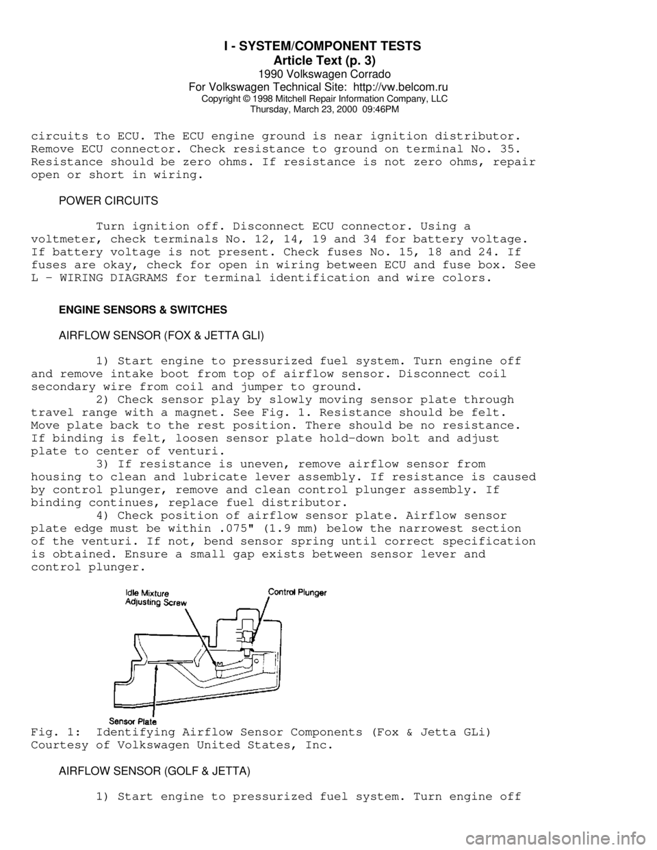
2) Check sensor play by slowly moving sensor plate through
travel range with a magnet. See Fig. 1. Resistance should be felt.
Move plate back to the rest position. There should be no resistance.
If binding is felt, loosen sensor plate hold-down bolt and adjust
plate to center of venturi.
3) If resistance is uneven, remove airflow sensor from
housing to clean and lubricate lever assembly. If resistance is caused
by control plunger, remove and clean control plunger assembly. If
binding continues, replace fuel distributor.
4) Check position of airflow sensor plate. Airflow sensor
plate edge must be within .075" (1.9 mm) below the narrowest section
of the venturi. If not, bend sensor spring until correct specification
is obtained. Ensure a small gap exists between sensor lever and
control plunger.Fig. 1: Identifying Airflow Sensor Components (Fox & Jetta GLi)
Courtesy of Volkswagen United States, Inc.
AIRFLOW SENSOR (GOLF & JETTA)
1) Start engine to pressurized fuel system. Turn engine off
Page 785 of 906

TROUBLE SHOOTING - BASIC PROCEDURES
Article Text (p. 9)
1990 Volkswagen Corrado
For Volkswagen Technical Site: http://vw.belcom.ru
Copyright © 1998 Mitchell Repair Information Company, LLC
Thursday, March 23, 2000 09:52PM
malfunction necessaryÄÄÄÄÄÄÄÄÄÄÄÄÄÄÄÄÄÄÄÄÄÄÄÄÄÄÄÄÄÄÄÄÄÄÄÄÄÄÄÄÄÄÄÄÄÄÄÄÄÄÄÄÄÄÄÄÄÄÄÄÄÄÄÄÄÄÄÄÄÄAlternator Light Loose or worn alternator Check alternator drive
Stays On With drive belt tension and
Engine Running condition, See Belt
Adjustment in TUNE-UP
article in the
TUNE-UP section
Loose alternator wiring Check all charging
connections system connections
Short in alternator light See Indicator Warning
wiring Lights in STANDARD
INSTRUMENTS in the
ACCESSORIES &
EQUIPMENT section
Defective alternator stator See Bench Tests in
or diodes ALTERNATOR article
Defective regulator See Regulator Check in
ALTERNATOR article
ÄÄÄÄÄÄÄÄÄÄÄÄÄÄÄÄÄÄÄÄÄÄÄÄÄÄÄÄÄÄÄÄÄÄÄÄÄÄÄÄÄÄÄÄÄÄÄÄÄÄÄÄÄÄÄÄÄÄÄÄÄÄÄÄÄÄÄÄÄÄAlternator Blown fuse See WIRING DIAGRAMS
Light Stays Off
With Ignition
Switch ON
Defective alternator See Testing in
ALTERNATOR article
Defective indicator light See Indicator Warning
bulb or socket Lights in STANDARD
INSTRUMENTS in the
ACCESSORIES &
EQUIPMENT section
ÄÄÄÄÄÄÄÄÄÄÄÄÄÄÄÄÄÄÄÄÄÄÄÄÄÄÄÄÄÄÄÄÄÄÄÄÄÄÄÄÄÄÄÄÄÄÄÄÄÄÄÄÄÄÄÄÄÄÄÄÄÄÄÄÄÄÄÄÄÄAlternator Short in alternator wiring See On-Vehicle Tests
Light Stays OFF in ALTERNATOR article
With Ignition
Switch ON
Defective rectifier bridge See Bench Tests in
ALTERNATOR article
ÄÄÄÄÄÄÄÄÄÄÄÄÄÄÄÄÄÄÄÄÄÄÄÄÄÄÄÄÄÄÄÄÄÄÄÄÄÄÄÄÄÄÄÄÄÄÄÄÄÄÄÄÄÄÄÄÄÄÄÄÄÄÄÄÄÄÄÄÄÄLights or Fuses Defective alternator wiring See On-Vehicle Tests
Burn Out in ALTERNATOR article
Frequently
Defective regulator See Regulator Check in
ALTERNATOR article
Page 894 of 906
WIRING DIAGRAM SYMBOLS
Article Text (p. 4)
1990 Volkswagen Corrado
For Volkswagen Technical Site: http://vw.belcom.ru
Copyright © 1998 Mitchell Repair Information Company, LLC
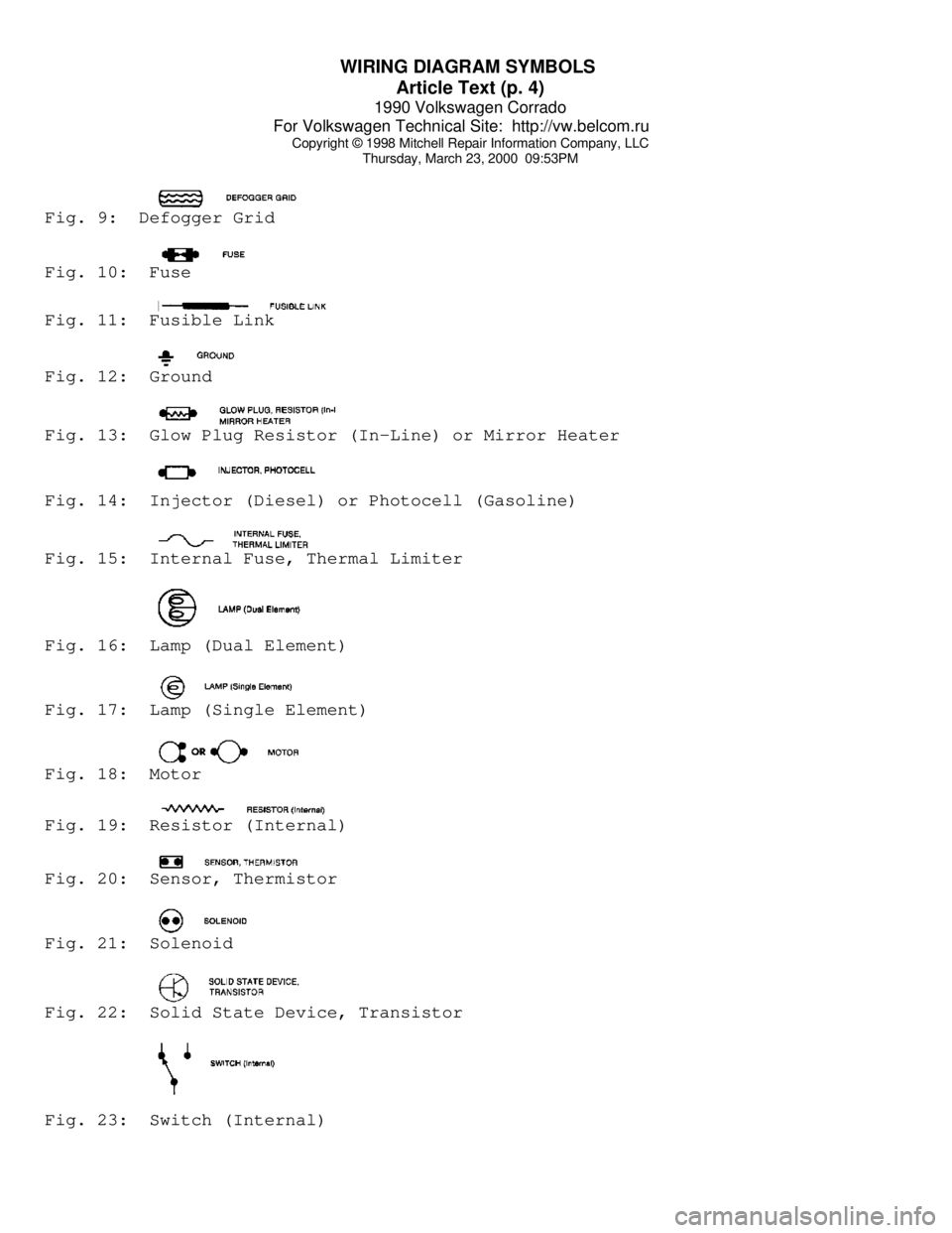
Thursday, March 23, 2000 09:53PMFig. 9: Defogger GridFig. 10: FuseFig. 11: Fusible LinkFig. 12: GroundFig. 13: Glow Plug Resistor (In-Line) or Mirror HeaterFig. 14: Injector (Diesel) or Photocell (Gasoline)Fig. 15: Internal Fuse, Thermal LimiterFig. 16: Lamp (Dual Element)Fig. 17: Lamp (Single Element)Fig. 18: MotorFig. 19: Resistor (Internal)Fig. 20: Sensor, ThermistorFig. 21: SolenoidFig. 22: Solid State Device, TransistorFig. 23: Switch (Internal)
Page 896 of 906

WIRING DIAGRAMS
Article Text
1990 Volkswagen Corrado
For Volkswagen Technical Site: http://vw.belcom.ru
Copyright © 1998 Mitchell Repair Information Company, LLC
Thursday, March 23, 2000 09:53PM
ARTICLE BEGINNING
1990 WIRING DIAGRAMS
Volkswagen
Corrado
COMPONENT LOCATION MENU
COMPONENT LOCATIONS TABLEÄÄÄÄÄÄÄÄÄÄÄÄÄÄÄÄÄÄÄÄÄÄÄÄÄÄÄÄÄÄÄÄÄÄÄÄÄÄÄÄÄÄÄÄÄÄÄÄÄÄÄÄÄÄÄÄÄÄÄÄComponent Figure No. (Location)
A/C COMP CLUTCH ................................. 4 (D 14)
A/C SYSTEM ................................. 4 (D-E 12-15)
ABS SYSTEM ................................... 2 (B-E 4-7)
ALTERNATOR ....................................... 1 (B 3)
AUTO SEAT BELTS ............................ 7 (B-E 25-27)
BACK-UP LIGHT SWITCH ............................ 6 (E 20)
BATTERY .......................................... 1 (A 2)
BEAM SELECT SWITCH .............................. 4 (A 12)
BRAKE & PARK BRAKE INDICATOR .................... 6 (A 22)
BRAKE FLUID LEVEL WARNING SWITCH ........ 2, 6 (E 6, A 23)
CASSETTE STORAGE LIGHT .......................... 6 (E 23)
CENTRAL LOCKS ................................ 8 (A 28-31)
CIG LIGHTER ..................................... 5 (A 16)
CRUISE CONTROL SYSTEM .......................... 2 (A 4-6)
DEFOG SWITCH .................................... 6 (E 21)
DIGIFANT CONTROL UNIT .......................... 1 (C-D 3)
DOOR SWITCHES ................................... 9 (E 35)
ECS-MALFUNCTION IND LIGHT & SWITCH ............... 3 (E 8)
EMERGENCY FLASHER SWITCH ..................... 4 (A 12-14)
FOG LIGHT ........................................ 1 (C 1)
FOG LIGHT SWITCH ................................ 4 (A 15)
FRESH AIR SWITCH ILLUM LIGHTS ................... 4 (D 12)
FUEL INJECTORS ................................. 1 (D-E 2)
FUEL PUMP AFTER RUN CONTROL UNIT ................ 3 (E 11)
FUEL TANK UNIT ................................ 3 (E 9-10)
FUS #23 ......................................... 4 (D 13)
FUSE/RELAY PANEL LAYOUT .................... 8 (D-E 29-31)
FUSE/RELAY PANEL ..................... 3, 4, 5, 6 (C 8-23)
GLOVE COMPT LIGHT ............................... 6 (D 23)
HEATED CRANKCASE BREATHER ....................... 3 (D 10)
HEATED SEATS ............................... 9 (C-E 32-34)
IGNITION COIL .................................... 1 (E 3)
IGNITION SWITCH .................................. 3 (A 8)
INSTRUMENT CLUSTER ......................... 7 (A-E 24-26)
INTERIOR LIGHT DELAY SWITCH ..................... 9 (E 33)
LEFT REAR MICRO SWITCH .......................... 7 (D 25)
LEFT SEAT BELT CONTROL UNIT ..................... 7 (D 27)
LIGHT SWITCH ................................. 3 (A 10-11)
LUGGAGE COMPT LIGHT ............................. 5 (A 17)
Page 900 of 906
WIRING DIAGRAMS
Article Text (p. 5)
1990 Volkswagen Corrado
For Volkswagen Technical Site: http://vw.belcom.ru
Copyright © 1998 Mitchell Repair Information Company, LLC
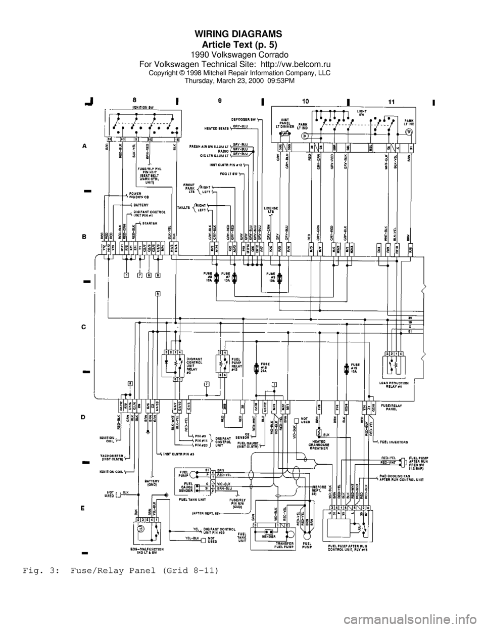
Thursday, March 23, 2000 09:53PMFig. 3: Fuse/Relay Panel (Grid 8-11)
Page 901 of 906
WIRING DIAGRAMS
Article Text (p. 6)
1990 Volkswagen Corrado
For Volkswagen Technical Site: http://vw.belcom.ru
Copyright © 1998 Mitchell Repair Information Company, LLC
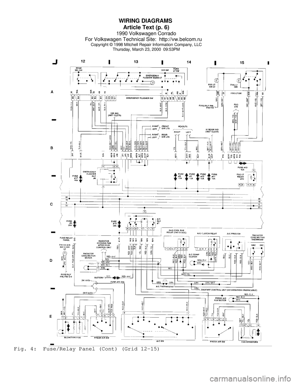
Thursday, March 23, 2000 09:53PMFig. 4: Fuse/Relay Panel (Cont) (Grid 12-15)
Page 902 of 906
WIRING DIAGRAMS
Article Text (p. 7)
1990 Volkswagen Corrado
For Volkswagen Technical Site: http://vw.belcom.ru
Copyright © 1998 Mitchell Repair Information Company, LLC
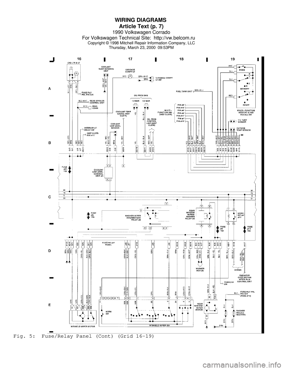
Thursday, March 23, 2000 09:53PMFig. 5: Fuse/Relay Panel (Cont) (Grid 16-19)