1990 VOLKSWAGEN CORRADO dimensions
[x] Cancel search: dimensionsPage 307 of 906

1.8L 4-CYL 8-VALVE & 1.8L 4-CYL 16-VALVE
Article Text (p. 16)
1990 Volkswagen Corrado
For Volkswagen Technical Site: http://vw.belcom.ru
Copyright © 1998 Mitchell Repair Information Company, LLC
Thursday, March 23, 2000 09:40PM
FITTING PISTONS & RINGS
1) DO NOT measure clearances with cylinder block mounted on
an engine stand. Check clearance of piston-to-cylinder bore. Piston
diameter is stamped on top of piston in millimeters. Arrow on top of
piston faces front of engine.
PISTON-TO-CYLINDER BORE DIMENSIONSÄÄÄÄÄÄÄÄÄÄÄÄÄÄÄÄÄÄÄÄÄÄÄÄÄÄÄÄÄÄÄÄÄÄÄÄÄÄÄÄÄÄÄÄÄÄÄÄÄÄÄÄÄÄÄ Piston Diameter Cylinder Bore
Size In. (mm) In. (mm)
Standard ....... 3.188 (80.98) ...... 3.189 (81.01)
1st Over ....... 3.198 (81.23) ...... 3.199 (81.26)
2nd Over ....... 3.208 (81.48) ...... 3.209 (81.51)
ÄÄÄÄÄÄÄÄÄÄÄÄÄÄÄÄÄÄÄÄÄÄÄÄÄÄÄÄÄÄÄÄÄÄÄÄÄÄÄÄÄÄÄÄÄÄÄÄÄÄÄÄÄÄÄ 2) Measure ring end gap. Measure ring side clearance with
piston. If not within specifications, replace as necessary. See ENGINE
SPECIFICATIONS at end of this article. Install rings on piston with
"TOP" mark facing upward. Recessed edge on outside of center ring must
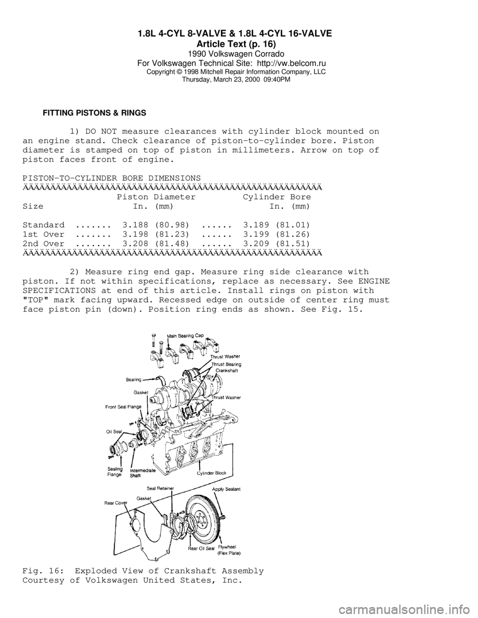
face piston pin (down). Position ring ends as shown. See Fig. 15.Fig. 16: Exploded View of Crankshaft Assembly
Courtesy of Volkswagen United States, Inc.
Page 510 of 906

ENGINE OVERHAUL PROCEDURES - GENERAL INFORMATION
Article Text
1990 Volkswagen Corrado
For Volkswagen Technical Site: http://vw.belcom.ru
Copyright © 1998 Mitchell Repair Information Company, LLC
Thursday, March 23, 2000 09:44PM
ARTICLE BEGINNING
Engine Overhaul Procedures - General Information
ALL PISTON ENGINES
* PLEASE READ THIS FIRST *
Examples used in this article are general in nature and do
not necessarily relate to a specific engine or system. Illustrations
and procedures have been chosen to guide mechanic through engine
overhaul process. Descriptions of processes of cleaning, inspection,
assembly and machine shop practice are included.
Always refer to appropriate engine overhaul article in the
ENGINES section for complete overhaul procedures and specifications
for the vehicle being repaired.
ENGINE IDENTIFICATION
The engine may be identified from its Vehicle Identification
Number (VIN) stamped on a metal tab. Metal tab may be located in
different locations depending on manufacturer. Engine identification
number or serial number is located on cylinder block. Location varies
with manufacturer.
INSPECTION PROCEDURES
* PLEASE READ THIS FIRST *
NOTE: Always refer to appropriate engine overhaul article in the
ENGINES section for complete overhaul procedures and
specifications for the vehicle being repaired.
GENERAL
Engine components must be inspected to meet manufacturer's
specifications and tolerances during overhaul. Proper dimensions and
tolerances must be met to obtain proper performance and maximum engine
life.
Micrometers, depth gauges and dial indicator are used for
checking tolerances during engine overhaul. Magnaflux, Magnaglo, dye-
check, ultrasonic and x-ray inspection procedures are used for parts
inspection.
MAGNETIC PARTICLE INSPECTION
Magnaflux & Magnaglo
Magnaflux is an inspection technique used to locate material
flaws and stress cracks. The part in question is subjected to a strong
magnetic field. The entire part, or a localized area, can be
magnetized. The part is coated with either a wet or dry material that
contains fine magnetic particles.
Page 519 of 906

ENGINE OVERHAUL PROCEDURES - GENERAL INFORMATION
Article Text (p. 10)
1990 Volkswagen Corrado
For Volkswagen Technical Site: http://vw.belcom.ru
Copyright © 1998 Mitchell Repair Information Company, LLC
Thursday, March 23, 2000 09:44PM
Replacing Valve Guide
Replace valve guide if clearance exceeds specification. Valve
guides are either pressed, hammered or shrunk in place, depending upon
cylinder head design and type of metal used.
Remove valve guide from cylinder head by pressing or tapping
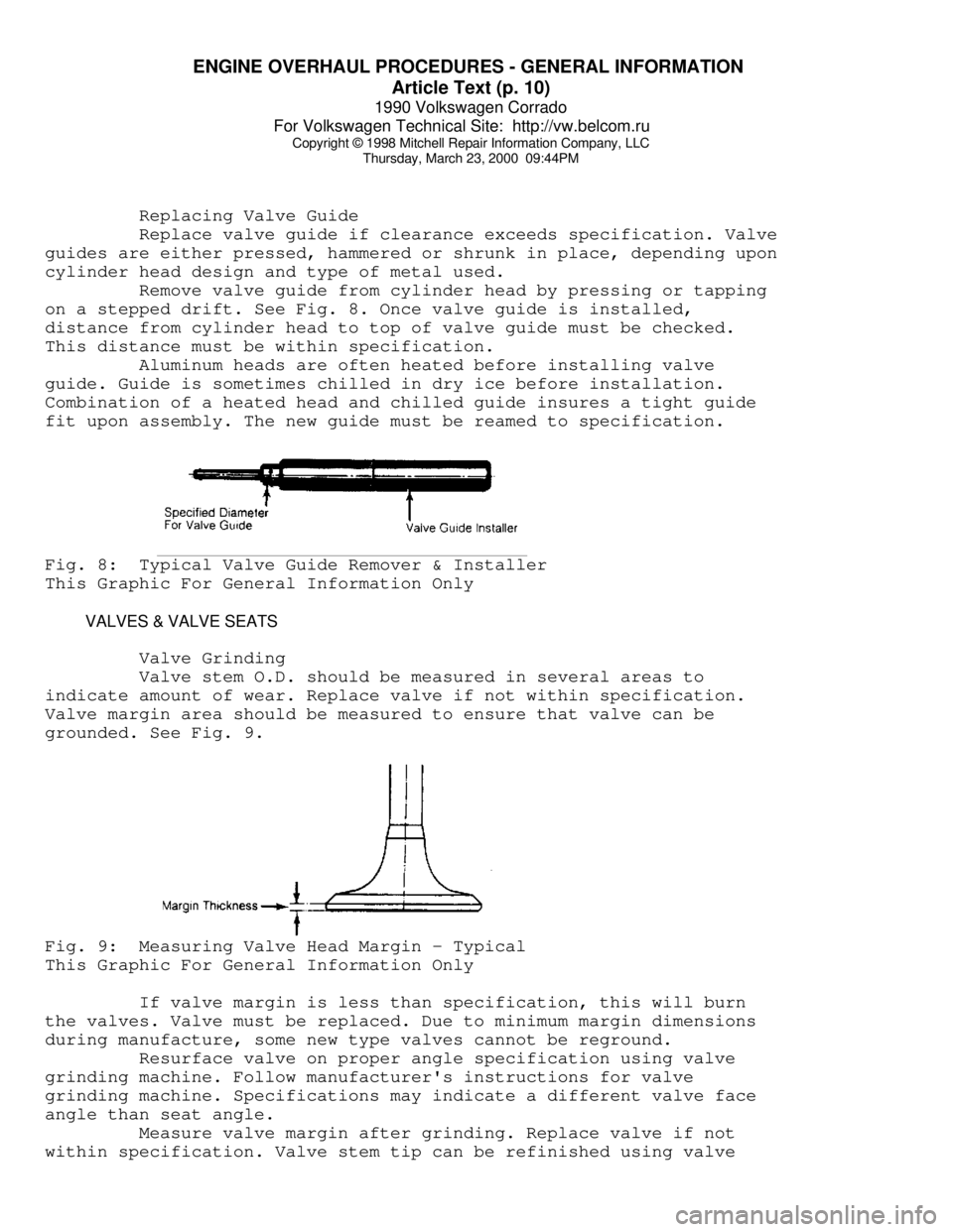
on a stepped drift. See Fig. 8. Once valve guide is installed,
distance from cylinder head to top of valve guide must be checked.
This distance must be within specification.
Aluminum heads are often heated before installing valve
guide. Guide is sometimes chilled in dry ice before installation.
Combination of a heated head and chilled guide insures a tight guide
fit upon assembly. The new guide must be reamed to specification.Fig. 8: Typical Valve Guide Remover & Installer
This Graphic For General Information Only
VALVES & VALVE SEATS
Valve Grinding
Valve stem O.D. should be measured in several areas to
indicate amount of wear. Replace valve if not within specification.
Valve margin area should be measured to ensure that valve can be
grounded. See Fig. 9.Fig. 9: Measuring Valve Head Margin - Typical
This Graphic For General Information Only
If valve margin is less than specification, this will burn
the valves. Valve must be replaced. Due to minimum margin dimensions
during manufacture, some new type valves cannot be reground.
Resurface valve on proper angle specification using valve
grinding machine. Follow manufacturer's instructions for valve
grinding machine. Specifications may indicate a different valve face
angle than seat angle.
Measure valve margin after grinding. Replace valve if not
within specification. Valve stem tip can be refinished using valve
Page 531 of 906

ENGINE OVERHAUL PROCEDURES - GENERAL INFORMATION
Article Text (p. 22)
1990 Volkswagen Corrado
For Volkswagen Technical Site: http://vw.belcom.ru
Copyright © 1998 Mitchell Repair Information Company, LLC
Thursday, March 23, 2000 09:44PM
rotated.
Remove bearing cap. Compare Plastigage width with scale on
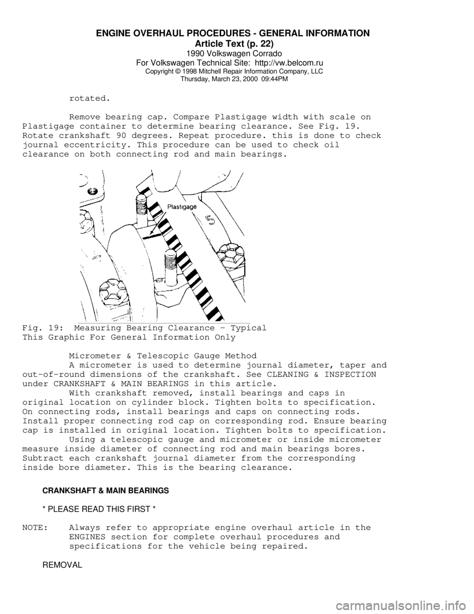
Plastigage container to determine bearing clearance. See Fig. 19.
Rotate crankshaft 90 degrees. Repeat procedure. this is done to check
journal eccentricity. This procedure can be used to check oil
clearance on both connecting rod and main bearings.Fig. 19: Measuring Bearing Clearance - Typical
This Graphic For General Information Only
Micrometer & Telescopic Gauge Method
A micrometer is used to determine journal diameter, taper and
out-of-round dimensions of the crankshaft. See CLEANING & INSPECTION
under CRANKSHAFT & MAIN BEARINGS in this article.
With crankshaft removed, install bearings and caps in
original location on cylinder block. Tighten bolts to specification.
On connecting rods, install bearings and caps on connecting rods.
Install proper connecting rod cap on corresponding rod. Ensure bearing
cap is installed in original location. Tighten bolts to specification.
Using a telescopic gauge and micrometer or inside micrometer
measure inside diameter of connecting rod and main bearings bores.
Subtract each crankshaft journal diameter from the corresponding
inside bore diameter. This is the bearing clearance.
CRANKSHAFT & MAIN BEARINGS
* PLEASE READ THIS FIRST *
NOTE: Always refer to appropriate engine overhaul article in the
ENGINES section for complete overhaul procedures and
specifications for the vehicle being repaired.
REMOVAL
Page 537 of 906

ENGINE OVERHAUL PROCEDURES - GENERAL INFORMATION
Article Text (p. 28)
1990 Volkswagen Corrado
For Volkswagen Technical Site: http://vw.belcom.ru
Copyright © 1998 Mitchell Repair Information Company, LLC
Thursday, March 23, 2000 09:44PM
Support camshaft at each end with "V" blocks. Position dial
indicator with tip resting on center bearing journal. Rotate camshaft
and note reading. If reading exceeds specification, replace camshaft.
Check cam lobe lift by measuring base circle of camshaft
using micrometer. Measure again at 90 degrees to tip of cam lobe. Cam
lift can be determined by subtracting base circle diameter from tip of
cam lobe measurement.
Different lift dimensions are given for intake and exhaust
cam lobes. Reading must be within specifications. Replace camshaft if
cam lobes or bearing journals are not within specifications.
Inspect camshaft gear for chipped, eroded or damaged teeth.
Replace gear if damaged. On camshafts using thrust plate, measure
distance between thrust plate and camshaft shoulder. Replace thrust
plate if not within specification.
CAMSHAFT BEARINGS
Removal & Installation
Remove the camshaft rear plug. The camshaft bearing remover
is assembled with its shoulder resting on the bearing to be removed
according to manufacturer's instructions. Tighten puller nut until
bearing is removed. Remove remaining bearings, leaving front and rear
bearings until last. These bearings act as guide for camshaft bearing
remover.
To install new bearings, puller is rearranged to pull
bearings toward the center of block. Ensure all lubrication passages
of bearing are aligned with cylinder block. Coat new camshaft rear
plug with sealant. Install camshaft rear plug. Ensure plug is even
in cylinder block.
CAMSHAFT INSTALLATION
Lubricate bearing surfaces and cam lobes with ample amount of
Molykote or camshaft lubricant. Carefully install camshaft. Use care
not to damage bearing journals during installation. Install thrust
plate retaining bolts (if equipped). Tighten bolts to specification.
On overhead camshafts, install bearing caps in original location.
Tighten bolts to specification. Check end play.
CAMSHAFT END PLAY
Using dial indicator, check end play. Position dial indicator
on front of engine block. Position indicator tip against camshaft.
Push camshaft toward rear of engine and adjust indicator to zero.
Move camshaft forward and note reading. Camshaft end play
must be within specification. End play may be adjusted by relocating
gear, shimming thrust plate or replacing thrust plate depending on
manufacturer.
TIMING CHAINS & BELTS
* PLEASE READ THIS FIRST *