1990 VOLKSWAGEN CORRADO transmission
[x] Cancel search: transmissionPage 2 of 906
J - PIN VOLTAGE CHARTSK - SENSOR RANGE CHARTSL - WIRING DIAGRAMSM - VACUUM DIAGRAMSMAINTENANCE INFORMATIONMAINTENANCE REMINDER LIGHT RESET PROCEDURESMETRIC CONVERSIONSMETRIC CONVERSIONSMIRRORS - POWERN - REMOVE/INSTALL/OVERHAULP - EGR FUNCTION TESTINGPOSSIBLE ENGINE STALL DUE TO FUEL RESTRICTIONPRE-ALIGNMENT CHECKSSCHEDULED SERVICESSERVICE INDICATOR & WARNING LIGHTSSTARTER - BOSCHSTEERING COLUMNSTEERING COLUMN SWITCHESSTEERING SYSTEM - POWERSUSPENSION - FRONTSUSPENSION - REARTRANSMISSION REMOVAL & INSTALLATION - A/TTRANSMISSION SERVICING - A/TTRANSMISSION SERVICING - M/TTROUBLE SHOOTING - BASIC PROCEDURESWAVEFORMS - INJECTOR PATTERN TUTORIALWHEEL ALIGNMENT SPECIFICATIONS & PROCEDURESWHEEL ALIGNMENT THEORY/OPERATIONWIPER/WASHER SYSTEMWIRING DIAGRAM SYMBOLSWIRING DIAGRAMS
Page 32 of 906

* AUTO TRANS DIAGNOSIS MENU - VOLKSWAGEN
Article Text
1990 Volkswagen Corrado
For Volkswagen Technical Site: http://vw.belcom.ru
Copyright © 1998 Mitchell Repair Information Company, LLC
Thursday, March 23, 2000 09:28PM
ARTICLE BEGINNING
AUTOMATIC TRANSMISSION DIAGNOSIS
ARTICLE SEARCH BY TRANSMISSION - IMPORTS
* PLEASE READ THIS FIRST *
The menu in this article pertains to articles that are
specifically written for the Electronically-Controlled transmission/
transaxle systems.
AUTO TRANS MENU - ALPHABETICAL - VOLKSWAGEN
VOLKSWAGEN
VOLKSWAGEN TRANSMISSIONSÚÄÄÄÄÄÄÄÄÄÄÄÄÄÄÂÄÄÄÄÄÄÄÄÄÄÄÄÄÄÄÄÄÄÄÄÄÄÄÄÄÄÄÄÄÄÄÄÄÄÄÄÄÄÄÄÄÄÄÄÄÄÄÄÄÄÄÄÄ¿
³ TRANSMISSION
³ GO TO: ³
ÃÄÄÄÄÄÄÄÄÄÄÄÄÄÄÅÄÄÄÄÄÄÄÄÄÄÄÄÄÄÄÄÄÄÄÄÄÄÄÄÄÄÄÄÄÄÄÄÄÄÄÄÄÄÄÄÄÄÄÄÄÄÄÄÄÄÄÄÄ´
³ 010
³ AUTO TRANS DIAGNOSIS - 010 ³
ÃÄÄÄÄÄÄÄÄÄÄÄÄÄÄÅÄÄÄÄÄÄÄÄÄÄÄÄÄÄÄÄÄÄÄÄÄÄÄÄÄÄÄÄÄÄÄÄÄÄÄÄÄÄÄÄÄÄÄÄÄÄÄÄÄÄÄÄÄ´
³ 096
³ AUTO TRANS DIAGNOSIS - 096 ³
ÃÄÄÄÄÄÄÄÄÄÄÄÄÄÄÅÄÄÄÄÄÄÄÄÄÄÄÄÄÄÄÄÄÄÄÄÄÄÄÄÄÄÄÄÄÄÄÄÄÄÄÄÄÄÄÄÄÄÄÄÄÄÄÄÄÄÄÄÄ´
³ 098
³ AUTO TRANS DIAGNOSIS - 098 ³
ÀÄÄÄÄÄÄÄÄÄÄÄÄÄÄÁÄÄÄÄÄÄÄÄÄÄÄÄÄÄÄÄÄÄÄÄÄÄÄÄÄÄÄÄÄÄÄÄÄÄÄÄÄÄÄÄÄÄÄÄÄÄÄÄÄÄÄÄÄÙEND OF ARTICLE
Page 104 of 906

* ENGINE SYSTEMS UNIFORM INSPECTION GUIDELINES *
Article Text (p. 7)
1990 Volkswagen Corrado
For Volkswagen Technical Site: http://vw.belcom.ru
Copyright © 1998 Mitchell Repair Information Company, LLC
Thursday, March 23, 2000 09:31PM
Leaking ³ Suggest replacement.
ÄÄÄÄÄÄÄÄÄÄÄÄÄÄÄÄÄÄÄÄÄÄÄÄÄÄÄÄÄÅÄÄÄÄÄÄÄÄÄÄÄÄÄÄÄÄÄÄÄÄÄÄÄÄÄÄÄÄÄÄÄÄÄÄÄÄÄÄÄÄMissing
³ Require replacement
ÄÄÄÄÄÄÄÄÄÄÄÄÄÄÄÄÄÄÄÄÄÄÄÄÄÄÄÄÄÁÄÄÄÄÄÄÄÄÄÄÄÄÄÄÄÄÄÄÄÄÄÄÄÄÄÄÄÄÄÄÄÄÄÄÄÄÄÄÄÄINDICATOR LIGHTS & GUAGES (TEMPERATURE, BRAKE, ENGINE OIL, CHARGING)
ÄÄÄÄÄÄÄÄÄÄÄÄÄÄÄÄÄÄÄÄÄÄÄÄÄÄÄÄÄÄÄÄÄÄÄÄÄÄÄÄÂÄÄÄÄÄÄÄÄÄÄÄÄÄÄÄÄÄÄÄÄÄÄÄÄÄÄÄÄÄCondition - Lights
³ Procedure
ÄÄÄÄÄÄÄÄÄÄÄÄÄÄÄÄÄÄÄÄÄÄÄÄÄÄÄÄÄÄÄÄÄÄÄÄÄÄÄÄÅÄÄÄÄÄÄÄÄÄÄÄÄÄÄÄÄÄÄÄÄÄÄÄÄÄÄÄÄÄLight doesn't come on during bulb check
³
ÄÄÄÄÄÄÄÄÄÄÄÄÄÄÄÄÄÄÄÄÄÄÄÄÄÄÄÄÄÄÄÄÄÄÄÄÄÄÄÄ´Fail to function properly during test
³ Further inspection required.
mode
³ See note.
ÄÄÄÄÄÄÄÄÄÄÄÄÄÄÄÄÄÄÄÄÄÄÄÄÄÄÄÄÄÄÄÄÄÄÄÄÄÄÄÄ´On constantly or intermittently
³
ÄÄÄÄÄÄÄÄÄÄÄÄÄÄÄÄÄÄÄÄÄÄÄÄÄÄÄÄÄÄÄÄÄÄÄÄÄÄÄÄÁÄÄÄÄÄÄÄÄÄÄÄÄÄÄÄÄÄÄÄÄÄÄÄÄÄÄÄÄÄNOTE: See service manual for further information.
ÄÄÄÄÄÄÄÄÄÄÄÄÄÄÄÄÄÄÄÄÄÄÄÄÄÄÄÄÄÄÄÄÄÂÄÄÄÄÄÄÄÄÄÄÄÄÄÄÄÄÄÄÄÄÄÄÄÄÄÄÄÄÄÄÄÄÄÄÄÄCondition - Guages
³ Procedure
ÄÄÄÄÄÄÄÄÄÄÄÄÄÄÄÄÄÄÄÄÄÄÄÄÄÄÄÄÄÄÄÄÄÅÄÄÄÄÄÄÄÄÄÄÄÄÄÄÄÄÄÄÄÄÄÄÄÄÄÄÄÄÄÄÄÄÄÄÄÄInoperative
³
ÄÄÄÄÄÄÄÄÄÄÄÄÄÄÄÄÄÄÄÄÄÄÄÄÄÄÄÄÄÄÄÄÄ´ Further inspection required.
Indicating out of manufacturer's
³ See note.
recommended range
³
ÄÄÄÄÄÄÄÄÄÄÄÄÄÄÄÄÄÄÄÄÄÄÄÄÄÄÄÄÄÄÄÄÄÁÄÄÄÄÄÄÄÄÄÄÄÄÄÄÄÄÄÄÄÄÄÄÄÄÄÄÄÄÄÄÄÄÄÄÄÄNOTE: See service manual for further information.
ÄÄÄÄÄÄÄÄÄÄÄÄÄÄÄÄÄÄÄÄÄÄÄÄÄÄÄÄÄÄÄÄÄÄÄÄÄÄÄÄÄÄÄÄÄÄÄÄÄÄÄÄÄÄÄÄÄÄÄÄÄÄÄÄÄÄÄÄÄÄDIP STICKS/TUBES
ÄÄÄÄÄÄÄÄÄÄÄÄÄÄÄÄÄÄÄÄÄÄÂÄÄÄÄÄÄÄÄÄÄÄÄÄÄÄÄÄÄÄÄÄÄÄÄÄÄÄÄÄÄÄÄÄÄÄÄÄÄÄÄÄÄÄÄÄÄÄCondition
³ Procedure
ÄÄÄÄÄÄÄÄÄÄÄÄÄÄÄÄÄÄÄÄÄÄÅÄÄÄÄÄÄÄÄÄÄÄÄÄÄÄÄÄÄÄÄÄÄÄÄÄÄÄÄÄÄÄÄÄÄÄÄÄÄÄÄÄÄÄÄÄÄÄMissing
³ Require replacement.
ÄÄÄÄÄÄÄÄÄÄÄÄÄÄÄÄÄÄÄÄÄÄÅÄÄÄÄÄÄÄÄÄÄÄÄÄÄÄÄÄÄÄÄÄÄÄÄÄÄÄÄÄÄÄÄÄÄÄÄÄÄÄÄÄÄÄÄÄÄÄIncorrect application
³ Require replacement.
ÄÄÄÄÄÄÄÄÄÄÄÄÄÄÄÄÄÄÄÄÄÄÅÄÄÄÄÄÄÄÄÄÄÄÄÄÄÄÄÄÄÄÄÄÄÄÄÄÄÄÄÄÄÄÄÄÄÄÄÄÄÄÄÄÄÄÄÄÄÄModified
³ Suggest replacement.
ÄÄÄÄÄÄÄÄÄÄÄÄÄÄÄÄÄÄÄÄÄÄÅÄÄÄÄÄÄÄÄÄÄÄÄÄÄÄÄÄÄÄÄÄÄÄÄÄÄÄÄÄÄÄÄÄÄÄÄÄÄÄÄÄÄÄÄÄÄÄBroken/damaged
³ Suggest replacement.
ÄÄÄÄÄÄÄÄÄÄÄÄÄÄÄÄÄÄÄÄÄÄÅÄÄÄÄÄÄÄÄÄÄÄÄÄÄÄÄÄÄÄÄÄÄÄÄÄÄÄÄÄÄÄÄÄÄÄÄÄÄÄÄÄÄÄÄÄÄÄLeaking
³ Suggest repair or replacement.
ÄÄÄÄÄÄÄÄÄÄÄÄÄÄÄÄÄÄÄÄÄÄÁÄÄÄÄÄÄÄÄÄÄÄÄÄÄÄÄÄÄÄÄÄÄÄÄÄÄÄÄÄÄÄÄÄÄÄÄÄÄÄÄÄÄÄÄÄÄÄCOOLERS (TRANSMISSION) EXTERNAL; ENGINE OIL; POWER STEERING
ÄÄÄÄÄÄÄÄÄÄÄÄÄÄÄÄÄÄÄÄÄÄÄÄÄÄÄÄÄÄÄÄÂÄÄÄÄÄÄÄÄÄÄÄÄÄÄÄÄÄÄÄÄÄÄÄÄÄÄÄÄÄÄÄÄÄÄÄÄÄCondition
³ Procedure
ÄÄÄÄÄÄÄÄÄÄÄÄÄÄÄÄÄÄÄÄÄÄÄÄÄÄÄÄÄÄÄÄÅÄÄÄÄÄÄÄÄÄÄÄÄÄÄÄÄÄÄÄÄÄÄÄÄÄÄÄÄÄÄÄÄÄÄÄÄÄLeaking
³ Require repair or replacement.
ÄÄÄÄÄÄÄÄÄÄÄÄÄÄÄÄÄÄÄÄÄÄÄÄÄÄÄÄÄÄÄÄÅÄÄÄÄÄÄÄÄÄÄÄÄÄÄÄÄÄÄÄÄÄÄÄÄÄÄÄÄÄÄÄÄÄÄÄÄÄDamaged fins, tubes or fittings
³ Suggest repair or replacement.
ÄÄÄÄÄÄÄÄÄÄÄÄÄÄÄÄÄÄÄÄÄÄÄÄÄÄÄÄÄÄÄÄÅÄÄÄÄÄÄÄÄÄÄÄÄÄÄÄÄÄÄÄÄÄÄÄÄÄÄÄÄÄÄÄÄÄÄÄÄÄInternal restrictions
³ Require repair or replacement.
Page 116 of 906

* ENGINE SYSTEMS UNIFORM INSPECTION GUIDELINES *
Article Text (p. 19)
1990 Volkswagen Corrado
For Volkswagen Technical Site: http://vw.belcom.ru
Copyright © 1998 Mitchell Repair Information Company, LLC
Thursday, March 23, 2000 09:31PM
POWERTRAIN CONTROL MODULE (PCM)ÄÄÄÄÄÄÄÄÄÄÄÄÄÄÄÄÄÄÄÄÄÄÂÄÄÄÄÄÄÄÄÄÄÄÄÄÄÄÄÄÄÄÄÄÄÄÄÄÄÄÄÄÄÄÄÄÄÄÄÄÄÄÄÄÄÄÄÄÄÄCondition
³ Procedure
ÄÄÄÄÄÄÄÄÄÄÄÄÄÄÄÄÄÄÄÄÄÄÅÄÄÄÄÄÄÄÄÄÄÄÄÄÄÄÄÄÄÄÄÄÄÄÄÄÄÄÄÄÄÄÄÄÄÄÄÄÄÄÄÄÄÄÄÄÄÄInoperative
³ Require repair or replacement.
ÄÄÄÄÄÄÄÄÄÄÄÄÄÄÄÄÄÄÄÄÄÄÅÄÄÄÄÄÄÄÄÄÄÄÄÄÄÄÄÄÄÄÄÄÄÄÄÄÄÄÄÄÄÄÄÄÄÄÄÄÄÄÄÄÄÄÄÄÄÄDamaged
³ Suggest repair or replacement.
ÄÄÄÄÄÄÄÄÄÄÄÄÄÄÄÄÄÄÄÄÄÄÁÄÄÄÄÄÄÄÄÄÄÄÄÄÄÄÄÄÄÄÄÄÄÄÄÄÄÄÄÄÄÄÄÄÄÄÄÄÄÄÄÄÄÄÄÄÄÄ SENSORS/ACTUATORS DEFINITIONS
NOTE: The conditions and procedures apply to, but are not limited
to the following list of components (SAE J1930 Terminology).
SENSORS/ACTUATORS DEFINITIONS
ÄÄÄÄÄÄÄÄÄÄÄÄÄÄÄÄÄÄÄÄÄÄÄÄÄÄÄÄÄÄÄÄÄÄÄÄÄÄÄÄÄÄÄÄÄÄÄÄÄÄÄÄÄÄÄÄÄÄÄÄÄÄÄÄÄÄÄÄÄÄSensor Abbreviation
02 Sensor ...................................... 02S
Intake Air Temperature Sensor .................. IAT
Manifold Absolute Pressure Sensor .............. MAP
Engine Coolant Temperature Sensor .............. ECT
Barometric Pressure Sensor ..................... BARO
Crankshaft Position Sensor ..................... CKP
Throttle Positon Sensor ........................ TPS
Camshaft Position Sensor ....................... CMP
Park Neutral Position .......................... PNP
Clutch Pedal Position Switch ................... CPP
Wide Open Throttle Switch ...................... WOT Switch
Exhaust Gas Recirculation
Valve Position Sensor ........................ EGR Valve
Position Sensor
Mass Air Flow Sensor ........................... MAF
Volume Air Flow Sensor ......................... VAF
Power Steering Pressure Sensor ................. PSP
Vehicle Speed Sensor ........................... VSS
Fan Control Sensor ............................. FS
Knock Sensor ................................... KS
Air Conditioning Cycling Switch ................ AC
Exhaust Gas Recirculating
Temperature Sensor ............................ EGRT
Transmission Range Switch ...................... TR Switch
Actuators Abbreviation
Idle Speed Control Actuator .................... ISC
Idle Air Control ............................... IAC
Exhaust Gas Recirculation Solenoid ............. EGR Solenoid
Vacuum Regulator Solenoid ...................... ...
Mix Control Solenoid ........................... MC Solenoid
Torque Converter Clutch ........................ TCC
Fuel Injector .................................. ...
Page 135 of 906

* ENGINE SYSTEMS UNIFORM INSPECTION GUIDELINES *
Article Text (p. 38)
1990 Volkswagen Corrado
For Volkswagen Technical Site: http://vw.belcom.ru
Copyright © 1998 Mitchell Repair Information Company, LLC
Thursday, March 23, 2000 09:32PM
Missing ³ Require replacement.
ÄÄÄÄÄÄÄÄÄÄÄÄÄÄÄÄÄÄÄÄÄÄÅÄÄÄÄÄÄÄÄÄÄÄÄÄÄÄÄÄÄÄÄÄÄÄÄÄÄÄÄÄÄÄÄÄÄÄÄÄÄÄÄÄÄÄÄÄÄÄDamaged
³ Suggest repair or replacement.
ÄÄÄÄÄÄÄÄÄÄÄÄÄÄÄÄÄÄÄÄÄÄÅÄÄÄÄÄÄÄÄÄÄÄÄÄÄÄÄÄÄÄÄÄÄÄÄÄÄÄÄÄÄÄÄÄÄÄÄÄÄÄÄÄÄÄÄÄÄÄInoperative
³ Require replacement.
ÄÄÄÄÄÄÄÄÄÄÄÄÄÄÄÄÄÄÄÄÄÄÅÄÄÄÄÄÄÄÄÄÄÄÄÄÄÄÄÄÄÄÄÄÄÄÄÄÄÄÄÄÄÄÄÄÄÄÄÄÄÄÄÄÄÄÄÄÄÄLeaking
³ Require replacement.
ÄÄÄÄÄÄÄÄÄÄÄÄÄÄÄÄÄÄÄÄÄÄÁÄÄÄÄÄÄÄÄÄÄÄÄÄÄÄÄÄÄÄÄÄÄÄÄÄÄÄÄÄÄÄÄÄÄÄÄÄÄÄÄÄÄÄÄÄÄÄ TRANSMISSION & CLUTCH RELATED INSPECTION INFORMATION
AUTOMATIC TRANSMISSION FILTER
ÄÄÄÄÄÄÄÄÄÄÄÄÄÄÄÄÄÄÄÄÄÄÂÄÄÄÄÄÄÄÄÄÄÄÄÄÄÄÄÄÄÄÄÄÄÄÄÄÄÄÄÄÄÄÄÄÄÄÄÄÄÄÄÄÄÄÄÄÄÄCondition
³ Procedure
ÄÄÄÄÄÄÄÄÄÄÄÄÄÄÄÄÄÄÄÄÄÄÅÄÄÄÄÄÄÄÄÄÄÄÄÄÄÄÄÄÄÄÄÄÄÄÄÄÄÄÄÄÄÄÄÄÄÄÄÄÄÄÄÄÄÄÄÄÄÄContaminated
³ Require replacement of fluid and filter.
ÄÄÄÄÄÄÄÄÄÄÄÄÄÄÄÄÄÄÄÄÄÄÅÄÄÄÄÄÄÄÄÄÄÄÄÄÄÄÄÄÄÄÄÄÄÄÄÄÄÄÄÄÄÄÄÄÄÄÄÄÄÄÄÄÄÄÄÄÄÄMaintenance intervals
³ Suggest replacement to comply with OEM
³ recommended service intervals.
ÄÄÄÄÄÄÄÄÄÄÄÄÄÄÄÄÄÄÄÄÄÄÁÄÄÄÄÄÄÄÄÄÄÄÄÄÄÄÄÄÄÄÄÄÄÄÄÄÄÄÄÄÄÄÄÄÄÄÄÄÄÄÄÄÄÄÄÄÄÄ TRANSMISSION FLUID
ÄÄÄÄÄÄÄÄÄÄÄÄÄÄÄÄÄÄÄÄÄÄÂÄÄÄÄÄÄÄÄÄÄÄÄÄÄÄÄÄÄÄÄÄÄÄÄÄÄÄÄÄÄÄÄÄÄÄÄÄÄÄÄÄÄÄÄÄÄÄCondition
³ Procedure
ÄÄÄÄÄÄÄÄÄÄÄÄÄÄÄÄÄÄÄÄÄÄÁÄÄÄÄÄÄÄÄÄÄÄÄÄÄÄÄÄÄÄÄÄÄÄÄÄÄÄÄÄÄÄÄÄÄÄÄÄÄÄÄÄÄÄÄÄÄÄSee * TRANSMISSION UNIFORM INSPECTION GUIDELINES *. (1)
ÄÄÄÄÄÄÄÄÄÄÄÄÄÄÄÄÄÄÄÄÄÄÄÄÄÄÄÄÄÄÄÄÄÄÄÄÄÄÄÄÄÄÄÄÄÄÄÄÄÄÄÄÄÄÄÄÄÄÄÄÄÄÄÄÄÄÄÄÄÄ(1) - TRANSMISSION UNIFORM INSPECTION GUIDELINES article is not
available at this time.
ÄÄÄÄÄÄÄÄÄÄÄÄÄÄÄÄÄÄÄÄÄÄÄÄÄÄÄÄÄÄÄÄÄÄÄÄÄÄÄÄÄÄÄÄÄÄÄÄÄÄÄÄÄÄÄÄÄÄÄÄÄÄÄÄÄÄÄÄÄÄ CLUTCH FLUID
ÄÄÄÄÄÄÄÄÄÄÄÄÄÄÄÄÄÄÄÄÄÄÂÄÄÄÄÄÄÄÄÄÄÄÄÄÄÄÄÄÄÄÄÄÄÄÄÄÄÄÄÄÄÄÄÄÄÄÄÄÄÄÄÄÄÄÄÄÄÄCondition
³ Procedure
ÄÄÄÄÄÄÄÄÄÄÄÄÄÄÄÄÄÄÄÄÄÄÁÄÄÄÄÄÄÄÄÄÄÄÄÄÄÄÄÄÄÄÄÄÄÄÄÄÄÄÄÄÄÄÄÄÄÄÄÄÄÄÄÄÄÄÄÄÄÄSee * TRANSMISSION UNIFORM INSPECTION GUIDELINES *. (1)
ÄÄÄÄÄÄÄÄÄÄÄÄÄÄÄÄÄÄÄÄÄÄÄÄÄÄÄÄÄÄÄÄÄÄÄÄÄÄÄÄÄÄÄÄÄÄÄÄÄÄÄÄÄÄÄÄÄÄÄÄÄÄÄÄÄÄÄÄÄÄ(1) - TRANSMISSION UNIFORM INSPECTION GUIDELINES article is not
available at this time.
ÄÄÄÄÄÄÄÄÄÄÄÄÄÄÄÄÄÄÄÄÄÄÄÄÄÄÄÄÄÄÄÄÄÄÄÄÄÄÄÄÄÄÄÄÄÄÄÄÄÄÄÄÄÄÄÄÄÄÄÄÄÄÄÄÄÄÄÄÄÄEND OF ARTICLE
Page 285 of 906
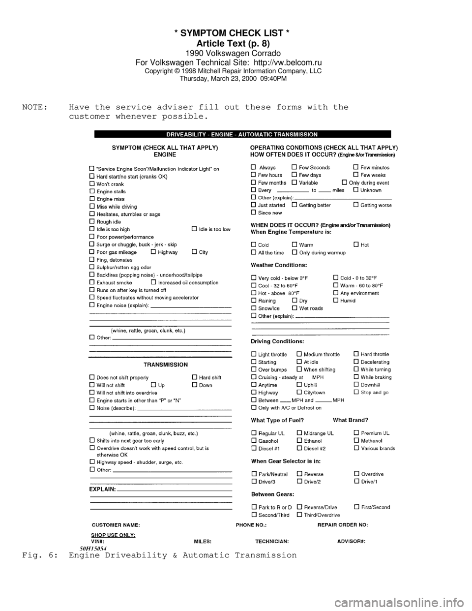
* SYMPTOM CHECK LIST *
Article Text (p. 8)
1990 Volkswagen Corrado
For Volkswagen Technical Site: http://vw.belcom.ru
Copyright © 1998 Mitchell Repair Information Company, LLC
Thursday, March 23, 2000 09:40PM
NOTE: Have the service adviser fill out these forms with the
customer whenever possible.Fig. 6: Engine Driveability & Automatic Transmission
Page 289 of 906
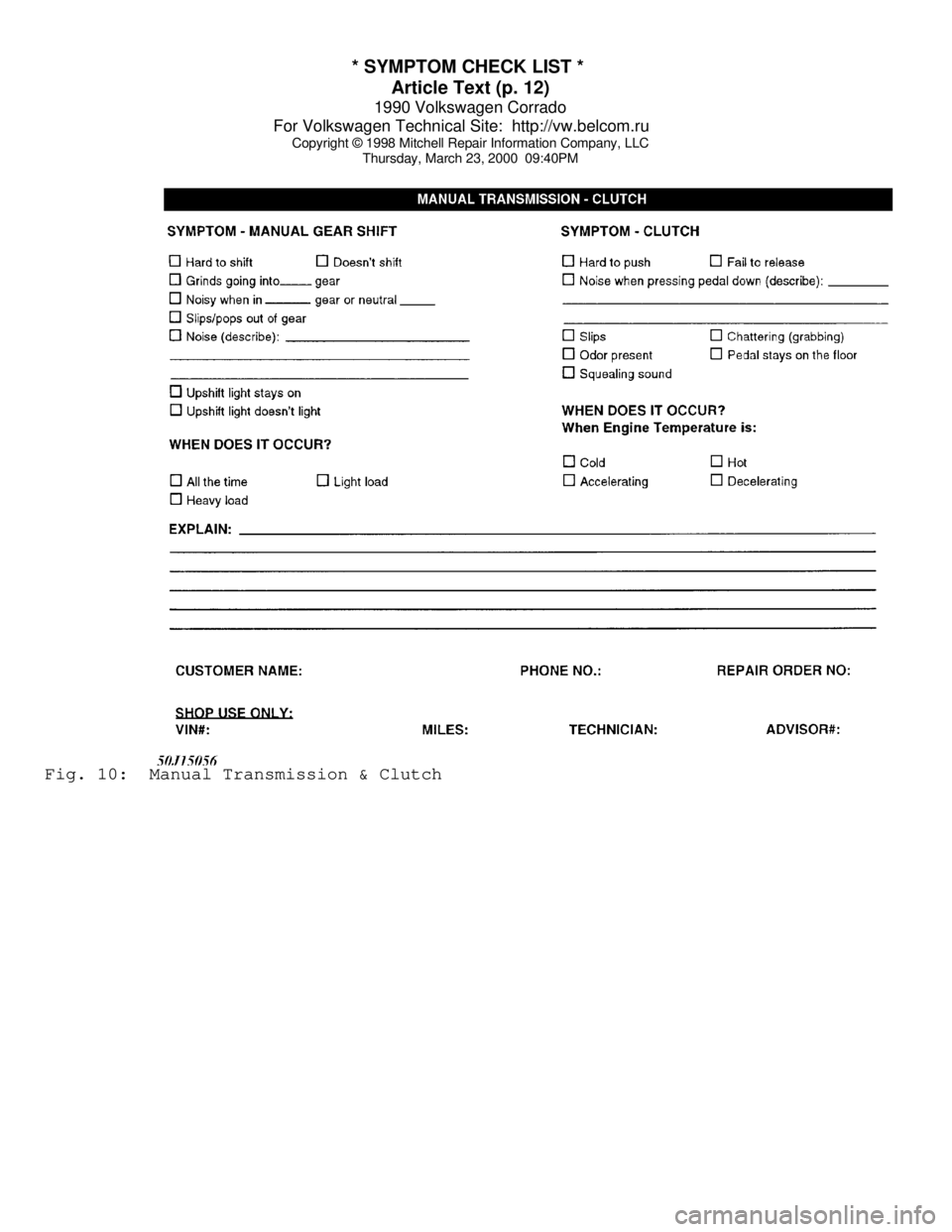
* SYMPTOM CHECK LIST *
Article Text (p. 12)
1990 Volkswagen Corrado
For Volkswagen Technical Site: http://vw.belcom.ru
Copyright © 1998 Mitchell Repair Information Company, LLC
Thursday, March 23, 2000 09:40PMFig. 10: Manual Transmission & Clutch
Page 293 of 906

1.8L 4-CYL 8-VALVE & 1.8L 4-CYL 16-VALVE
Article Text (p. 2)
1990 Volkswagen Corrado
For Volkswagen Technical Site: http://vw.belcom.ru
Copyright © 1998 Mitchell Repair Information Company, LLC
Thursday, March 23, 2000 09:40PM
NOTE: Match mark engine mounts to ensure original alignment is
achieved after installation. On vehicles with A/C and power
steering, remove components with hoses attached and secure
out of way.
ENGINE R & I (EXCEPT FOX)
REMOVAL (EXCEPT FOX)
1) Disconnect and remove battery. Open fuel tank fill cap and
radiator cap. Remove intake air duct. On 16-valve engines, remove
intake manifold assembly. On vehicles with A/C, remove trim panel and
lower apron. Remove condenser from crossmember and radiator. Remove
all duct work. Mark and disconnect A/C and cooling fan electrical
connectors. Remove accessory belts.
2) On Golf, GTI and Jetta models, leave A/C hoses attached
and remove A/C compressor. Pivot A/C condenser and compressor to side
of vehicle and secure.
3) On Cabriolet and Scirocco models, remove alternator and
timing belt cover. Remove 3 A/C bracket Allen head bolts behind timing
belt cover. Remove A/C bracket support brace. Remove A/C compressor
bracket bolts. Leave hoses attached and secure A/C compressor with
bracket out of way.
4) On all models, open heater controls. Remove cooling hose
from thermostat housing flange and drain coolant. Remove flange. Mark
and remove all cooling system hoses (as necessary).
5) On Golf, GTI and Jetta models, remove grille from radiator
support. Disconnect electrical connectors at radiator support. Remove
radiator-to-support bolts. Remove radiator support using care not
damage headlights. Remove radiator, fan and shroud assembly.
6) On all models, remove axle shafts from transaxle. See FWD
AXLE SHAFTS article in the DRIVE AXLES section. Mark and disconnect
shift linkage and speedometer cable. Mark and remove electrical
connectors and vacuum hoses (as necessary). Disconnect throttle,
cruise and kickdown cables (if equipped). Leave fuel lines connected
and remove cold start injector and warm-up regulator.
7) Remove fuel injectors and install protective caps and
plugs. Remove rear engine mount. Remove complete transaxle mount. On
Cabriolet models, remove right front tire assembly. Remove right and
left engine mount through bolts.
8) On all models, install engine sling on engine lift hooks.
Carefully raise engine and transaxle out of vehicle. Separate
transaxle from engine (if necessary).
INSTALLATION
1) To install, reverse removal procedure. Engine alignment
adjustment is necessary whenever engine is removed or mounts are
loosened. To adjust, loosen through bolt on engine mount "A". Loosen
transmission transaxle mount "B" bolts. Loosen front engine mount and
bracket. See Fig. 2.
2) Lightly rock engine and transaxle to allow position to