1990 VOLKSWAGEN CORRADO wheel bolts
[x] Cancel search: wheel boltsPage 308 of 906

1.8L 4-CYL 8-VALVE & 1.8L 4-CYL 16-VALVE
Article Text (p. 17)
1990 Volkswagen Corrado
For Volkswagen Technical Site: http://vw.belcom.ru
Copyright © 1998 Mitchell Repair Information Company, LLC
Thursday, March 23, 2000 09:40PM
PISTON PIN REPLACEMENT R & I
Ensure piston and rod are properly marked. Remove both
circlips from pin bore groove. Use Piston Pin Replacer (VW 207C) to
remove and install the piston pin. If pin is too tight, heat piston to
140øF (60øC). To install, reverse removal procedure. Ensure rod is
properly positioned with piston. See Fig. 15.
CRANKSHAFT R & I
1) Using flywheel Holder (10-201), remove flywheel bolts.
Remove flywheel. Remove front and rear oil seals and covers. Remove
connecting rod bearing caps.
2) Measure crankshaft end play. See CRANKSHAFT END PLAY CHECK
in this article. Remove main bearing cap bolts. Remove main bearing
caps. Remove crankshaft. To install, reverse removal procedure.
MAIN BEARING INSTALLATION
Main bearing caps are marked with matching journal and must
be installed to original position. See Fig. 16. Thrust bearing is
located at No. 3 main bearing cap. Use Plastigage method to check
clearance. Machine or replace as necessary. See ENGINE SPECIFICATIONS
at end of this article. Tighten evenly to specifications in several
steps.
CONNECTING ROD BEARING INSTALLATION
Ensure rod caps are marked to ensure installation to original
position and location. Use Plastigage to measure bearing clearances.
Measure connecting rod side play. Replace or machine as necessary. See
ENGINE SPECIFICATIONS at end of this article. Tighten evenly to
specifications in several steps.
CRANKSHAFT END PLAY CHECK
Insert feeler gauge between No. 3 main bearing and crankshaft
thrust face to measure end play. See Fig. 16. Replace thrust bearing
as necessary. See ENGINE SPECIFICATIONS at end of this article.
Original thrust bearing uses plain shell with 4 separate washers and
replacements have attached collar.
REAR MAIN BEARING OIL SEAL R & I
Remove flywheel/flex plate and discard retaining bolts. Oil
seal may removed without removing retaining flange by prying seal out.
Remove retaining flange if gasket is leaking. See Fig. 16. If
installing without removing retaining flange, use Centering Tool
(2003/2A) to center seal and Installer (2003/1) to install seal.
Page 309 of 906

1.8L 4-CYL 8-VALVE & 1.8L 4-CYL 16-VALVE
Article Text (p. 18)
1990 Volkswagen Corrado
For Volkswagen Technical Site: http://vw.belcom.ru
Copyright © 1998 Mitchell Repair Information Company, LLC
Thursday, March 23, 2000 09:40PM
Install new flywheel bolts.
FRONT COVER OIL SEAL R & I
REMOVAL
Remove timing belt. See REMOVAL under TIMING BELT R & I in
this article. Rotate inner part of Oil Seal Extractor (2085) outward 2
turns and tighten set screw. See Fig. 11. Lubricate threaded area of
extractor and push in as far as possible. Loosen set screw and turn
inner part of extractor until oil seal is removed.
INSTALLATION
Lubricate outer edge and lip of new seal. Place guide sleeve
from Seal Installer (3083) onto crankshaft. Push oil seal over guide
sleeve. Press seal completely into position. To complete installation,
reverse removal procedure.
INTERMEDIATE SHAFT ASSEMBLY
Remove timing belt. See REMOVAL under TIMING BELT in this
article. Mark distributor assembly for installation reference and
remove distributor assembly. Check intermediate shaft end play. See
INTERMEDIATE SHAFT END PLAY SPECIFICATION table following this
paragraph. Remove intermediate shaft sprocket. Remove intermediate
shaft seal flange. Replace seal (if necessary). To install, reverse
removal procedure. See ENGINE SPECIFICATIONS at end of this article.
INTERMEDIATE SHAFT END PLAY SPECIFICATIONÄÄÄÄÄÄÄÄÄÄÄÄÄÄÄÄÄÄÄÄÄÄÄÄÄÄÄÄÄÄÄÄÄÄÄÄÄÄÄÄÄÄÄÄÄApplication In. (mm)
1.8L ........................... .010 (.25)
ÄÄÄÄÄÄÄÄÄÄÄÄÄÄÄÄÄÄÄÄÄÄÄÄÄÄÄÄÄÄÄÄÄÄÄÄÄÄÄÄÄÄÄÄÄ CYLINDER BLOCK INSPECTION
DO NOT measure cylinder block while mounted on an engine
stand. Inaccurate measurements may be achieved. Check cylinder bore
for wear, out-of-round and taper. Pistons are available in oversize.
Cylinder block bore may be machined. Check cylinder block for warpage.
See ENGINE SPECIFICATIONS at end of this article.
ENGINE OILING SYSTEM SPECIFICATIONS
CRANKCASE CAPACITY
CRANKCASE CAPACITY TABLE
ÄÄÄÄÄÄÄÄÄÄÄÄÄÄÄÄÄÄÄÄÄÄÄÄÄÄÄÄÄÄÄÄÄÄÄÄÄÄÄÄÄÄÄÄÄÄÄÄÄÄÄÄÄÄÄ With Filter Without Filter
Page 312 of 906

1.8L 4-CYL 8-VALVE & 1.8L 4-CYL 16-VALVE
Article Text (p. 21)
1990 Volkswagen Corrado
For Volkswagen Technical Site: http://vw.belcom.ru
Copyright © 1998 Mitchell Repair Information Company, LLC
Thursday, March 23, 2000 09:40PM
Engine Mounts (4)
A Bolt/Nut ..................................... 18 (24)
B Bolt ......................................... 22 (30)
C Bolt ......................................... 44 (60)
D Bolt ......................................... 53 (72)
E Bolt ......................................... 59 (80)
Engine-to-Transaxle Bolt
M10 ............................................ 33 (45)
M12 ............................................ 55 (75)
Exhaust Manifold Nut ............................. 18 (24)
Flywheel-to-Crankshaft Bolt (5) ................. 74 (100)
Intake Manifold Bolt ............................. 18 (24)
Intermediate Shaft Sprocket Bolt
8-Valve ........................................ 59 (80)
16-Valve ....................................... 48 (65)
Main Bearing Cap Bolt (6) ........................ 48 (65)
Oil Pan Bolt ..................................... 15 (20)
Oil Pump
Short Bolt ...................................... 7 (10)
Long Bolt ...................................... 15 (20)
Power Steering Pump-to-Bracket Nut ............... 14 (19)
Timing Belt Tensioner Pulley Nut ................. 33 (45)
Water Pump Housing-to-Block ...................... 15 (20)
Water Pump Pulley ................................ 15 (20)
INCH Lbs. (N.m)
Piston Oil Spray
Nozzle Bolt .................................... 84 (10)
Thermostat Housing-to-Water
Pump Housing ................................... 84 (10)
Upper & Lower Timing Belt Cover Bolt .............. 53 (6)
Water Pump-to-Housing ............................ 84 (10)
(1) - Tighten an additional 180 degrees. Ensure a new bolt
is used.
(2) - Tighten in sequence. See Fig. 5.
(3) - Turn bolts 180 degrees further in one continuous
movement. Two separate 90 degree turns may be used.
(4) - See Fig. 2.
(5) - Apply sealant to threads and tighten evenly and
diagonally.
(6) - Tighten in several steps evenly.ÄÄÄÄÄÄÄÄÄÄÄÄÄÄÄÄÄÄÄÄÄÄÄÄÄÄÄÄÄÄÄÄÄÄÄÄÄÄÄÄÄÄÄÄÄÄÄÄÄÄÄÄÄÄÄÄÄÄÄÄ ENGINE SPECIFICATIONS
GENERAL ENGINE SPECIFICATIONS
GENERAL SPECIFICATIONS TABLE
ÄÄÄÄÄÄÄÄÄÄÄÄÄÄÄÄÄÄÄÄÄÄÄÄÄÄÄÄÄÄÄÄÄÄÄÄÄÄÄÄÄÄÄÄÄÄÄÄÄÄÄÄÄÄÄÄÄÄÄÄApplication Specifications
Page 439 of 906

D - ADJUSTMENTS
Article Text (p. 2)
1990 Volkswagen Corrado
For Volkswagen Technical Site: http://vw.belcom.ru
Copyright © 1998 Mitchell Repair Information Company, LLC
Thursday, March 23, 2000 09:43PM
connected, timing mark on flywheel should appear at pointer in hole.
NOTE: Before checking engine timing, raise engine speed above 2100
RPM at least 4 times. This must be done each time ignition
is turned off and restarted to clear ECU memory and by-pass
hot-start, fast-idle function.
3) If an adjustment is needed, turn ignition off and loosen
distributor hold-down bolt (2.0L has 2 hold-down bolts) just enough to
move distributor by hand. Start engine and allow to idle. Turn
distributor until timing mark is aligned with pointer in bellhousing.
4) Stop engine and tighten hold down bolt to 18 ft. lbs. (24
N.m). On 2.0L tighten hold-down bolts to 87 INCH lbs. (10 N.m). Check
and readjust if necessary and install plastic plug in inspection hole.
VANAGON
1) Engine oil temperature must be 176ø F (80ø C). Connect
timing light and tachometer. Start engine and allow to idle. Check
ignition timing at 800-1000 RPM.
NOTE: Before checking engine timing, raise engine speed above 2100
RPM at least 4 times. This must be done each time ignition
is turned off and restarted to clear ECU memory and by-pass
hot-start, fast-idle function.
2) If an adjustment is needed, turn ignition off and loosen
distributor hold-down bolt just enough to move distributor by hand.
Remove connectors from idle stabilizer by squeezing connectors then
pulling apart. Plug idle stabilizer connectors together.
3) Start and allow engine to idle. Turn distributor until
notch on V-belt pulley matches separation in case. Set timing and RPM.
Reconnect electrical connectors to idle stabilizer. Tighten
distributor clamp bolt.
IGNITION TIMING TABLE
IGNITION TIMING (Degrees BTDC @ RPM)
ÄÄÄÄÄÄÄÄÄÄÄÄÄÄÄÄÄÄÄÄÄÄÄÄÄÄÄÄÄÄÄÄÄÄÄÄÄÄÄÄÄÄÄÄÄÄÄÄÄÄÄÄÄÄÄÄÄÄÄÄÄÄÄÄÄÄÄÄÄÄApplication Checking Adjusting
1.8L ..................... 4-8 @ 870-930 ........... 5-7 @ 870-930
2.0L ..................... 4-8 @ 770-830 ........... 5-7 @ 770-830
2.1L ..................... 4-8 @ 800-900 ........... 5-7 @ 800-900
ÄÄÄÄÄÄÄÄÄÄÄÄÄÄÄÄÄÄÄÄÄÄÄÄÄÄÄÄÄÄÄÄÄÄÄÄÄÄÄÄÄÄÄÄÄÄÄÄÄÄÄÄÄÄÄÄÄÄÄÄÄÄÄÄÄÄÄÄÄÄ COLD (FAST) IDLE
Fast idle RPM is not adjustable.
IDLE SPEED & MIXTURE
Page 738 of 906

STEERING COLUMN
Article Text (p. 4)
1990 Volkswagen Corrado
For Volkswagen Technical Site: http://vw.belcom.ru
Copyright © 1998 Mitchell Repair Information Company, LLC
Thursday, March 23, 2000 09:51PM
toward instrument panel. Pry spacer sleeve from column.
2) Pull up combination switch to disconnect wires. Remove
combination switch. Disconnect steering shaft from "U" joint shaft.
Disconnect brake pedal push rod.
3) Disconnect clutch cable from clutch pedal. Using a
screwdriver, push down leaf spring retainer clip to disengage it from
mounting slot.
4) Remove bolts that retain steering column under instrument
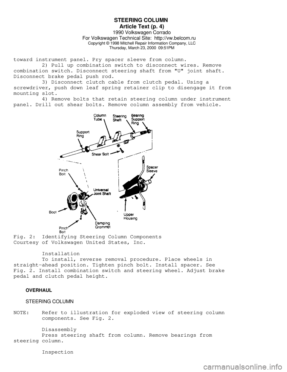
panel. Drill out shear bolts. Remove column assembly from vehicle.Fig. 2: Identifying Steering Column Components
Courtesy of Volkswagen United States, Inc.
Installation
To install, reverse removal procedure. Place wheels in
straight-ahead position. Tighten pinch bolt. Install spacer. See
Fig. 2. Install combination switch and steering wheel. Adjust brake
pedal and clutch pedal height.
OVERHAUL
STEERING COLUMN
NOTE: Refer to illustration for exploded view of steering column
components. See Fig. 2.
Disassembly
Press steering shaft from column. Remove bearings from
steering column.
Inspection
Page 750 of 906

STEERING SYSTEM - POWER
Article Text (p. 3)
1990 Volkswagen Corrado
For Volkswagen Technical Site: http://vw.belcom.ru
Copyright © 1998 Mitchell Repair Information Company, LLC
Thursday, March 23, 2000 09:51PM
3) If pump pressure is not within specification, replace
pump.
STEERING WHEEL TURNING FORCE
Except Vanagon
Remove steering gear. See POWER RACK & PINION under REMOVAL &
INSTALLATION. Loosen lock nut. Turn adjuster bolt until pinion shaft
can be turned by hand without binding. Hold adjuster bolt in position
while tightening lock nut.
Vanagon
If steering effort is too high, check steering shaft,
steering linkage, "U" joints, and ball joints for binding. If all are
okay, replace steering gear.
REMOVAL & INSTALLATION
POWER STEERING PUMP
Removal
Remove alternator and pump belts. Disconnect hydraulic lines
from pump. Cap lines to prevent contamination. Remove bracket bolts.
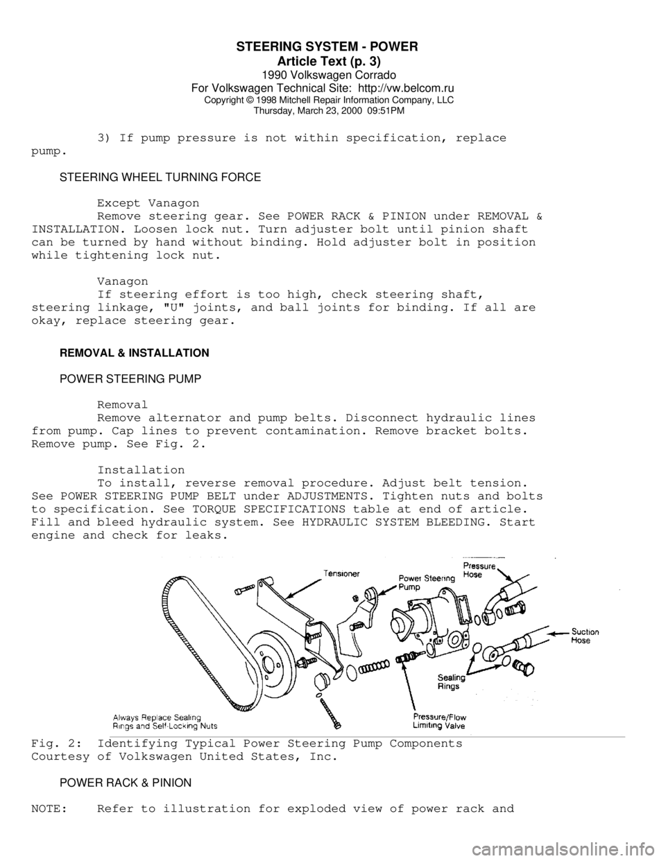
Remove pump. See Fig. 2.
Installation
To install, reverse removal procedure. Adjust belt tension.
See POWER STEERING PUMP BELT under ADJUSTMENTS. Tighten nuts and bolts
to specification. See TORQUE SPECIFICATIONS table at end of article.
Fill and bleed hydraulic system. See HYDRAULIC SYSTEM BLEEDING. Start
engine and check for leaks.Fig. 2: Identifying Typical Power Steering Pump Components
Courtesy of Volkswagen United States, Inc.
POWER RACK & PINION
NOTE: Refer to illustration for exploded view of power rack and
Page 751 of 906

STEERING SYSTEM - POWER
Article Text (p. 4)
1990 Volkswagen Corrado
For Volkswagen Technical Site: http://vw.belcom.ru
Copyright © 1998 Mitchell Repair Information Company, LLC
Thursday, March 23, 2000 09:51PM
pinion components. See Fig. 1.
Removal (Cabriolet)
1) Remove pressure line from pump. Drain fluid from pump and
line. Disconnect tie rod ends from steering knuckles. Remove
transmission mount and bracket. Remove exhaust manifold.
2) Remove hydraulic lines from steering gear. Plug openings.
Remove shift linkage from steering gear (if equipped). Remove ground
wire. Disconnect pinion shaft at "U" joint. Remove retaining bolts and
steering gear.
Removal (Corrado)
1) Disconnect return line from pump. Drain fluid from pump
and line. Disconnect tie rod ends from steering knuckles.
2) Remove lock bolt at "U" joint. Remove steering gear
retaining bolts. Disconnect hydraulic lines at steering gear. Plug
openings.
3) Support engine and transmission. Remove subframe bolts.
Remove steering gear.
Removal (Golf, GTI & Jetta)
1) Disconnect return line from pump. Drain fluid from pump
and line. Disconnect tie rod ends from steering knuckles.
2) Remove shift linkage from steering gear (if equipped).
Disconnect pinion shaft at "U" joint. Disconnect hydraulic lines from
steering gear. Plug openings. Remove retaining bolts.
3) Support engine and transmission with Engine Support (10-
222A). Remove left transmission mount bolts. Loosen right transmission
mount bolts. Remove steering gear.
Removal (Passat)
1) Disconnect return line from pump. Drain fluid from pump
and line. Disconnect tie rod ends from steering knuckles.
2) Support engine and transmission with Engine Support (10-
222A and 10-222A/1). Remove steering gear boot. Remove transmission
mount bolts. Lower engine/transmission sufficiently to separate
steering shaft halves.
3) Disconnect hydraulic lines from steering gear. Plug
openings. Remove retaining nuts and steering gear.
Removal (Vanagon)
1) Removal and installation information is not available from
manufacturer.
Installation (All Models)
Reverse removal procedure to install. Tighten nuts and bolts
to specification. See TORQUE SPECIFICATIONS table at end of article.
Fill and bleed hydraulic system. See HYDRAULIC SYSTEM BLEEDING. Check
wheel alignment. See appropriate WHEEL ALIGNMENT SPECIFICATIONS &
PROCEDURES article in the WHEEL ALIGNMENT section:
* WHEEL ALIGNMENT SPECIFICATIONS & PROCEDURES - (1990 - All
Page 755 of 906

SUSPENSION - FRONT
Article Text (p. 3)
1990 Volkswagen Corrado
For Volkswagen Technical Site: http://vw.belcom.ru
Copyright © 1998 Mitchell Repair Information Company, LLC
Thursday, March 23, 2000 09:51PM
REMOVAL & INSTALLATION
HUB & KNUCKLE ASSEMBLY
Use exploded view illustration when removing or installing
hub and knuckle assembly. See Fig. 1 or 2.
LOWER CONTROL ARM & BALL JOINT
Removal
1) Raise and support vehicle. Remove bolt retaining ball
joint at wheel bearing housing. Force ball joint from of housing.
Leave control arm hanging in mounts at subframe.
2) If control arm is not to be removed and ball joint is
riveted to control arm, drill out ball joint rivets using a 9/32" (7
mm) drill. After drilling rivets, chisel off rivet heads if necessary.
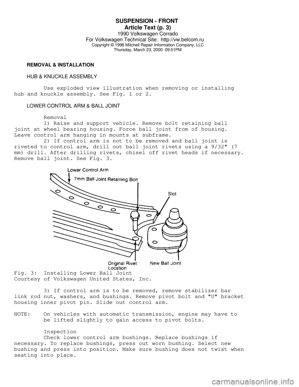
Remove ball joint. See Fig. 3.Fig. 3: Installing Lower Ball Joint
Courtesy of Volkswagen United States, Inc.
3) If control arm is to be removed, remove stabilizer bar
link rod nut, washers, and bushings. Remove pivot bolt and "U" bracket
housing inner pivot pin. Slide out control arm.
NOTE: On vehicles with automatic transmission, engine may have to
be lifted slightly to gain access to pivot bolts.
Inspection
Check lower control arm bushings. Replace bushings if
necessary. To replace bushings, press out worn bushing. Select new
bushing and press into position. Make sure bushing does not twist when
seating into place.