1990 VOLKSWAGEN CORRADO wheel torque
[x] Cancel search: wheel torquePage 60 of 906

* BRAKE SYSTEM UNIFORM INSPECTION GUIDELINES *
Article Text (p. 28)
1990 Volkswagen Corrado
For Volkswagen Technical Site: http://vw.belcom.ru
Copyright © 1998 Mitchell Repair Information Company, LLC
Thursday, March 23, 2000 09:29PM
For conditions noted below, also check conditions of wheel
stud holes.
CAUTION: Proper lug nut torque is essential. Follow manufacturer's
torque specifications and tightening sequence.
DO NOT lubricate threads unless specified by the vehicle
manufacturer.
WHEEL ATTACHING HARDWAREÄÄÄÄÄÄÄÄÄÄÄÄÄÄÄÄÄÄÄÄÄÂÄÄÄÄÄÄÂÄÄÄÄÄÄÄÄÄÄÄÄÄÄÄÄÄÄÄÄÄÄÄÄÄÄÄÄÄÄÄÄÄÄÄÄÄÄÄÄÄCondition
³ Code ³ Procedure
ÄÄÄÄÄÄÄÄÄÄÄÄÄÄÄÄÄÄÄÄÄÅÄÄÄÄÄÄÅÄÄÄÄÄÄÄÄÄÄÄÄÄÄÄÄÄÄÄÄÄÄÄÄÄÄÄÄÄÄÄÄÄÄÄÄÄÄÄÄÄBent
³ A ³ Require replacement.
ÄÄÄÄÄÄÄÄÄÄÄÄÄÄÄÄÄÄÄÄÄÅÄÄÄÄÄÄÅÄÄÄÄÄÄÄÄÄÄÄÄÄÄÄÄÄÄÄÄÄÄÄÄÄÄÄÄÄÄÄÄÄÄÄÄÄÄÄÄÄBroken
³ A ³ Require replacement. See note (1) below.
ÄÄÄÄÄÄÄÄÄÄÄÄÄÄÄÄÄÄÄÄÄÅÄÄÄÄÄÄÅÄÄÄÄÄÄÄÄÄÄÄÄÄÄÄÄÄÄÄÄÄÄÄÄÄÄÄÄÄÄÄÄÄÄÄÄÄÄÄÄÄLoose
³ A ³ Require repair or replacement of
³ ³ affected component.
ÄÄÄÄÄÄÄÄÄÄÄÄÄÄÄÄÄÄÄÄÄÅÄÄÄÄÄÄÅÄÄÄÄÄÄÄÄÄÄÄÄÄÄÄÄÄÄÄÄÄÄÄÄÄÄÄÄÄÄÄÄÄÄÄÄÄÄÄÄÄLug nut installed
³ A ³ Require repair.
backward
³ ³
ÄÄÄÄÄÄÄÄÄÄÄÄÄÄÄÄÄÄÄÄÄÅÄÄÄÄÄÄÅÄÄÄÄÄÄÄÄÄÄÄÄÄÄÄÄÄÄÄÄÄÄÄÄÄÄÄÄÄÄÄÄÄÄÄÄÄÄÄÄÄLug nut mating type
³ A ³ Require replacement of nut.
incorrect
³ ³
ÄÄÄÄÄÄÄÄÄÄÄÄÄÄÄÄÄÄÄÄÄÅÄÄÄÄÄÄÅÄÄÄÄÄÄÄÄÄÄÄÄÄÄÄÄÄÄÄÄÄÄÄÄÄÄÄÄÄÄÄÄÄÄÄÄÄÄÄÄÄLug nut mating
³ A ³ Require replacement of nut.
surface dished
³ ³
ÄÄÄÄÄÄÄÄÄÄÄÄÄÄÄÄÄÄÄÄÄÅÄÄÄÄÄÄÅÄÄÄÄÄÄÄÄÄÄÄÄÄÄÄÄÄÄÄÄÄÄÄÄÄÄÄÄÄÄÄÄÄÄÄÄÄÄÄÄÄLug nut flats rounded
³ A ³ Require replacement of nut. See note (2)
ÄÄÄÄÄÄÄÄÄÄÄÄÄÄÄÄÄÄÄÄÄÅÄÄÄÄÄÄÅÄÄÄÄÄÄÄÄÄÄÄÄÄÄÄÄÄÄÄÄÄÄÄÄÄÄÄÄÄÄÄÄÄÄÄÄÄÄÄÄÄLug nut seized
³ A ³ Require replacement of nut and/or stud.
³ ³ See note (2) below.
ÄÄÄÄÄÄÄÄÄÄÄÄÄÄÄÄÄÄÄÄÄÅÄÄÄÄÄÄÅÄÄÄÄÄÄÄÄÄÄÄÄÄÄÄÄÄÄÄÄÄÄÄÄÄÄÄÄÄÄÄÄÄÄÄÄÄÄÄÄÄStud incorrect
³ A ³ Require replacement of stud.
ÄÄÄÄÄÄÄÄÄÄÄÄÄÄÄÄÄÄÄÄÄÅÄÄÄÄÄÄÅÄÄÄÄÄÄÄÄÄÄÄÄÄÄÄÄÄÄÄÄÄÄÄÄÄÄÄÄÄÄÄÄÄÄÄÄÄÄÄÄÄThreads damaged
³ A ³ Require repair or replacement of
³ ³ component with damaged threads.
ÄÄÄÄÄÄÄÄÄÄÄÄÄÄÄÄÄÄÄÄÄÅÄÄÄÄÄÄÅÄÄÄÄÄÄÄÄÄÄÄÄÄÄÄÄÄÄÄÄÄÄÄÄÄÄÄÄÄÄÄÄÄÄÄÄÄÄÄÄÄThreads stripped
³ A ³ Require replacement of component with
(threads missing)
³ ³ stripped threads.
ÄÄÄÄÄÄÄÄÄÄÄÄÄÄÄÄÄÄÄÄÄÁÄÄÄÄÄÄÁÄÄÄÄÄÄÄÄÄÄÄÄÄÄÄÄÄÄÄÄÄÄÄÄÄÄÄÄÄÄÄÄÄÄÄÄÄÄÄÄÄNOTE: (1) Some manufacturers require replacement of all studs on that
wheel if two or more studs or nuts on the same wheel are
broken or missing.
(2) Only required if removing wheel.
ÄÄÄÄÄÄÄÄÄÄÄÄÄÄÄÄÄÄÄÄÄÄÄÄÄÄÄÄÄÄÄÄÄÄÄÄÄÄÄÄÄÄÄÄÄÄÄÄÄÄÄÄÄÄÄÄÄÄÄÄÄÄÄÄÄÄÄÄÄÄ WHEEL BEARINGS, RACES, & SEALS
NOTE: When repacking or replacing wheel bearings, grease seal
replacement is required. You are not required to replace these
components in axle sets. Determine the need to replace based
Page 209 of 906

* STEERING UNIFORM INSPECTION GUIDELINES *
Article Text (p. 64)
1990 Volkswagen Corrado
For Volkswagen Technical Site: http://vw.belcom.ru
Copyright © 1998 Mitchell Repair Information Company, LLC
Thursday, March 23, 2000 09:35PMÄÄÄÄÄÄÄÄÄÄÄÄÄÄÄÄÄÄÄÄÄÄÄÄÄÄÄÄÄÄÄÄÄÄÅÄÄÄÄÄÄÅÄÄÄÄÄÄÄÄÄÄÄÄÄÄÄÄÄÄÄÄÄÄÄÄÄÄÄÄMissing
³ C ³ Require replacement.
ÄÄÄÄÄÄÄÄÄÄÄÄÄÄÄÄÄÄÄÄÄÄÄÄÄÄÄÄÄÄÄÄÄÄÅÄÄÄÄÄÄÅÄÄÄÄÄÄÄÄÄÄÄÄÄÄÄÄÄÄÄÄÄÄÄÄÄÄÄÄThreads damaged
³ A ³ Require repair/replacement.
ÄÄÄÄÄÄÄÄÄÄÄÄÄÄÄÄÄÄÄÄÄÄÄÄÄÄÄÄÄÄÄÄÄÄÅÄÄÄÄÄÄÅÄÄÄÄÄÄÄÄÄÄÄÄÄÄÄÄÄÄÄÄÄÄÄÄÄÄÄÄThreads stripped (threads missing)
³ A ³ Require replacement.
ÄÄÄÄÄÄÄÄÄÄÄÄÄÄÄÄÄÄÄÄÄÄÄÄÄÄÄÄÄÄÄÄÄÄÅÄÄÄÄÄÄÅÄÄÄÄÄÄÄÄÄÄÄÄÄÄÄÄÄÄÄÄÄÄÄÄÄÄÄÄValve cap missing
³ C ³ Require replacement of cap.
ÄÄÄÄÄÄÄÄÄÄÄÄÄÄÄÄÄÄÄÄÄÄÄÄÄÄÄÄÄÄÄÄÄÄÅÄÄÄÄÄÄÅÄÄÄÄÄÄÄÄÄÄÄÄÄÄÄÄÄÄÄÄÄÄÄÄÄÄÄÄWeather-checking
³ A,1 ³ Suggest replacement.
ÄÄÄÄÄÄÄÄÄÄÄÄÄÄÄÄÄÄÄÄÄÄÄÄÄÄÄÄÄÄÄÄÄÄÅÄÄÄÄÄÄÅÄÄÄÄÄÄÄÄÄÄÄÄÄÄÄÄÄÄÄÄÄÄÄÄÄÄÄÄWon't take air
³ A ³ Require repair/replacement.
ÄÄÄÄÄÄÄÄÄÄÄÄÄÄÄÄÄÄÄÄÄÄÄÄÄÄÄÄÄÄÄÄÄÄÁÄÄÄÄÄÄÁÄÄÄÄÄÄÄÄÄÄÄÄÄÄÄÄÄÄÄÄÄÄÄÄÄÄÄÄ WHEEL ATTACHMENT HARDWARE
For conditions noted below, also check conditions of wheel
stud holes.
CAUTION: Proper lug nut torque is essential. Follow manufacturer's
torque specifications and tightening sequence. DO NOT
lubricate threads unless specified by the vehicle
manufacturer.
WHEEL ATTACHMENT HARDWARE
ÄÄÄÄÄÄÄÄÄÄÄÄÄÄÄÄÄÄÄÄÄÄÄÄÄÄÄÄÄÂÄÄÄÄÄÄÂÄÄÄÄÄÄÄÄÄÄÄÄÄÄÄÄÄÄÄÄÄÄÄÄÄÄÄÄÄÄÄÄÄCondition
³ Code ³ Procedure
ÄÄÄÄÄÄÄÄÄÄÄÄÄÄÄÄÄÄÄÄÄÄÄÄÄÄÄÄÄÅÄÄÄÄÄÄÅÄÄÄÄÄÄÄÄÄÄÄÄÄÄÄÄÄÄÄÄÄÄÄÄÄÄÄÄÄÄÄÄÄBent
³ A ³ Require replacement.
ÄÄÄÄÄÄÄÄÄÄÄÄÄÄÄÄÄÄÄÄÄÄÄÄÄÄÄÄÄÅÄÄÄÄÄÄÅÄÄÄÄÄÄÄÄÄÄÄÄÄÄÄÄÄÄÄÄÄÄÄÄÄÄÄÄÄÄÄÄÄBroken
³ A ³ Require replacement.
³ ³ See note (1) below.
ÄÄÄÄÄÄÄÄÄÄÄÄÄÄÄÄÄÄÄÄÄÄÄÄÄÄÄÄÄÅÄÄÄÄÄÄÅÄÄÄÄÄÄÄÄÄÄÄÄÄÄÄÄÄÄÄÄÄÄÄÄÄÄÄÄÄÄÄÄÄLoose
³ B ³ Require repair or replacement
³ ³ of affected component.
ÄÄÄÄÄÄÄÄÄÄÄÄÄÄÄÄÄÄÄÄÄÄÄÄÄÄÄÄÄÅÄÄÄÄÄÄÅÄÄÄÄÄÄÄÄÄÄÄÄÄÄÄÄÄÄÄÄÄÄÄÄÄÄÄÄÄÄÄÄÄLug nut installed backward
³ B ³ Require repair.
ÄÄÄÄÄÄÄÄÄÄÄÄÄÄÄÄÄÄÄÄÄÄÄÄÄÄÄÄÄÅÄÄÄÄÄÄÅÄÄÄÄÄÄÄÄÄÄÄÄÄÄÄÄÄÄÄÄÄÄÄÄÄÄÄÄÄÄÄÄÄLug nut mating type incorrect
³ B ³ Require replacement of nut.
ÄÄÄÄÄÄÄÄÄÄÄÄÄÄÄÄÄÄÄÄÄÄÄÄÄÄÄÄÄÅÄÄÄÄÄÄÅÄÄÄÄÄÄÄÄÄÄÄÄÄÄÄÄÄÄÄÄÄÄÄÄÄÄÄÄÄÄÄÄÄLug nut mating surface dished
³ A ³ Require replacement of nut.
ÄÄÄÄÄÄÄÄÄÄÄÄÄÄÄÄÄÄÄÄÄÄÄÄÄÄÄÄÄÅÄÄÄÄÄÄÅÄÄÄÄÄÄÄÄÄÄÄÄÄÄÄÄÄÄÄÄÄÄÄÄÄÄÄÄÄÄÄÄÄLug nut flats rounded
³ A ³ Require replacement of nut.
³ ³ See note (2) below.
ÄÄÄÄÄÄÄÄÄÄÄÄÄÄÄÄÄÄÄÄÄÄÄÄÄÄÄÄÄÅÄÄÄÄÄÄÅÄÄÄÄÄÄÄÄÄÄÄÄÄÄÄÄÄÄÄÄÄÄÄÄÄÄÄÄÄÄÄÄÄLug nut seized
³ A ³ Require replacement of nut
³ ³ and/or stud. See note (2) below.
ÄÄÄÄÄÄÄÄÄÄÄÄÄÄÄÄÄÄÄÄÄÄÄÄÄÄÄÄÄÅÄÄÄÄÄÄÅÄÄÄÄÄÄÄÄÄÄÄÄÄÄÄÄÄÄÄÄÄÄÄÄÄÄÄÄÄÄÄÄÄStud incorrect
³ B ³ Require replacement of stud.
ÄÄÄÄÄÄÄÄÄÄÄÄÄÄÄÄÄÄÄÄÄÄÄÄÄÄÄÄÄÅÄÄÄÄÄÄÅÄÄÄÄÄÄÄÄÄÄÄÄÄÄÄÄÄÄÄÄÄÄÄÄÄÄÄÄÄÄÄÄÄThreads damaged
³ A ³ Require repair or replacement of
³ ³ component with damaged threads.
Page 275 of 906

* SUSPENSION UNIFORM INSPECTION GUIDELINES *
Article Text (p. 64)
1990 Volkswagen Corrado
For Volkswagen Technical Site: http://vw.belcom.ru
Copyright © 1998 Mitchell Repair Information Company, LLC
Thursday, March 23, 2000 09:39PMÄÄÄÄÄÄÄÄÄÄÄÄÄÄÄÄÄÄÄÄÄÄÄÄÄÄÄÄÄÄÄÄÄÄÅÄÄÄÄÄÄÅÄÄÄÄÄÄÄÄÄÄÄÄÄÄÄÄÄÄÄÄÄÄÄÄÄÄÄÄMissing
³ C ³ Require replacement.
ÄÄÄÄÄÄÄÄÄÄÄÄÄÄÄÄÄÄÄÄÄÄÄÄÄÄÄÄÄÄÄÄÄÄÅÄÄÄÄÄÄÅÄÄÄÄÄÄÄÄÄÄÄÄÄÄÄÄÄÄÄÄÄÄÄÄÄÄÄÄThreads damaged
³ A ³ Require repair/replacement.
ÄÄÄÄÄÄÄÄÄÄÄÄÄÄÄÄÄÄÄÄÄÄÄÄÄÄÄÄÄÄÄÄÄÄÅÄÄÄÄÄÄÅÄÄÄÄÄÄÄÄÄÄÄÄÄÄÄÄÄÄÄÄÄÄÄÄÄÄÄÄThreads stripped (threads missing)
³ A ³ Require replacement.
ÄÄÄÄÄÄÄÄÄÄÄÄÄÄÄÄÄÄÄÄÄÄÄÄÄÄÄÄÄÄÄÄÄÄÅÄÄÄÄÄÄÅÄÄÄÄÄÄÄÄÄÄÄÄÄÄÄÄÄÄÄÄÄÄÄÄÄÄÄÄValve cap missing
³ C ³ Require replacement of cap.
ÄÄÄÄÄÄÄÄÄÄÄÄÄÄÄÄÄÄÄÄÄÄÄÄÄÄÄÄÄÄÄÄÄÄÅÄÄÄÄÄÄÅÄÄÄÄÄÄÄÄÄÄÄÄÄÄÄÄÄÄÄÄÄÄÄÄÄÄÄÄWeather-checking
³ A,1 ³ Suggest replacement.
ÄÄÄÄÄÄÄÄÄÄÄÄÄÄÄÄÄÄÄÄÄÄÄÄÄÄÄÄÄÄÄÄÄÄÅÄÄÄÄÄÄÅÄÄÄÄÄÄÄÄÄÄÄÄÄÄÄÄÄÄÄÄÄÄÄÄÄÄÄÄWon't take air
³ A ³ Require repair/replacement.
ÄÄÄÄÄÄÄÄÄÄÄÄÄÄÄÄÄÄÄÄÄÄÄÄÄÄÄÄÄÄÄÄÄÄÁÄÄÄÄÄÄÁÄÄÄÄÄÄÄÄÄÄÄÄÄÄÄÄÄÄÄÄÄÄÄÄÄÄÄÄ WHEEL ATTACHMENT HARDWARE
For conditions noted below, also check conditions of wheel
stud holes.
CAUTION: Proper lug nut torque is essential. Follow manufacturer's
torque specifications and tightening sequence. DO NOT
lubricate threads unless specified by the vehicle
manufacturer.
WHEEL ATTACHMENT HARDWARE
ÄÄÄÄÄÄÄÄÄÄÄÄÄÄÄÄÄÄÄÄÄÄÄÄÄÄÄÄÄÂÄÄÄÄÄÄÂÄÄÄÄÄÄÄÄÄÄÄÄÄÄÄÄÄÄÄÄÄÄÄÄÄÄÄÄÄÄÄÄÄCondition
³ Code ³ Procedure
ÄÄÄÄÄÄÄÄÄÄÄÄÄÄÄÄÄÄÄÄÄÄÄÄÄÄÄÄÄÅÄÄÄÄÄÄÅÄÄÄÄÄÄÄÄÄÄÄÄÄÄÄÄÄÄÄÄÄÄÄÄÄÄÄÄÄÄÄÄÄBent
³ A ³ Require replacement.
ÄÄÄÄÄÄÄÄÄÄÄÄÄÄÄÄÄÄÄÄÄÄÄÄÄÄÄÄÄÅÄÄÄÄÄÄÅÄÄÄÄÄÄÄÄÄÄÄÄÄÄÄÄÄÄÄÄÄÄÄÄÄÄÄÄÄÄÄÄÄBroken
³ A ³ Require replacement.
³ ³ See note (1) below.
ÄÄÄÄÄÄÄÄÄÄÄÄÄÄÄÄÄÄÄÄÄÄÄÄÄÄÄÄÄÅÄÄÄÄÄÄÅÄÄÄÄÄÄÄÄÄÄÄÄÄÄÄÄÄÄÄÄÄÄÄÄÄÄÄÄÄÄÄÄÄLoose
³ B ³ Require repair or replacement
³ ³ of affected component.
ÄÄÄÄÄÄÄÄÄÄÄÄÄÄÄÄÄÄÄÄÄÄÄÄÄÄÄÄÄÅÄÄÄÄÄÄÅÄÄÄÄÄÄÄÄÄÄÄÄÄÄÄÄÄÄÄÄÄÄÄÄÄÄÄÄÄÄÄÄÄLug nut installed backward
³ B ³ Require repair.
ÄÄÄÄÄÄÄÄÄÄÄÄÄÄÄÄÄÄÄÄÄÄÄÄÄÄÄÄÄÅÄÄÄÄÄÄÅÄÄÄÄÄÄÄÄÄÄÄÄÄÄÄÄÄÄÄÄÄÄÄÄÄÄÄÄÄÄÄÄÄLug nut mating type incorrect
³ B ³ Require replacement of nut.
ÄÄÄÄÄÄÄÄÄÄÄÄÄÄÄÄÄÄÄÄÄÄÄÄÄÄÄÄÄÅÄÄÄÄÄÄÅÄÄÄÄÄÄÄÄÄÄÄÄÄÄÄÄÄÄÄÄÄÄÄÄÄÄÄÄÄÄÄÄÄLug nut mating surface dished
³ A ³ Require replacement of nut.
ÄÄÄÄÄÄÄÄÄÄÄÄÄÄÄÄÄÄÄÄÄÄÄÄÄÄÄÄÄÅÄÄÄÄÄÄÅÄÄÄÄÄÄÄÄÄÄÄÄÄÄÄÄÄÄÄÄÄÄÄÄÄÄÄÄÄÄÄÄÄLug nut flats rounded
³ A ³ Require replacement of nut.
³ ³ See note (2) below.
ÄÄÄÄÄÄÄÄÄÄÄÄÄÄÄÄÄÄÄÄÄÄÄÄÄÄÄÄÄÅÄÄÄÄÄÄÅÄÄÄÄÄÄÄÄÄÄÄÄÄÄÄÄÄÄÄÄÄÄÄÄÄÄÄÄÄÄÄÄÄLug nut seized
³ A ³ Require replacement of nut
³ ³ and/or stud. See note (2) below.
ÄÄÄÄÄÄÄÄÄÄÄÄÄÄÄÄÄÄÄÄÄÄÄÄÄÄÄÄÄÅÄÄÄÄÄÄÅÄÄÄÄÄÄÄÄÄÄÄÄÄÄÄÄÄÄÄÄÄÄÄÄÄÄÄÄÄÄÄÄÄStud incorrect
³ B ³ Require replacement of stud.
ÄÄÄÄÄÄÄÄÄÄÄÄÄÄÄÄÄÄÄÄÄÄÄÄÄÄÄÄÄÅÄÄÄÄÄÄÅÄÄÄÄÄÄÄÄÄÄÄÄÄÄÄÄÄÄÄÄÄÄÄÄÄÄÄÄÄÄÄÄÄThreads damaged
³ A ³ Require repair or replacement of
³ ³ component with damaged threads.
Page 419 of 906

ANTI-LOCK BRAKE SYSTEM
Article Text (p. 11)
1990 Volkswagen Corrado
For Volkswagen Technical Site: http://vw.belcom.ru
Copyright © 1998 Mitchell Repair Information Company, LLC
Thursday, March 23, 2000 09:42PM
REMOVAL & INSTALLATION
HYDRAULIC MODULATOR/PUMP
Removal & Installation
1) Depressurize brake system. See DEPRESSURIZING BRAKE
SYSTEM. Disconnect negative battery cable. Unplug all electrical
connectors from hydraulic modulator/pump. Identify and disconnect all
hydraulic lines from hydraulic modulator/pump. Plug all line openings.
2) From inside passenger compartment, remove push rod clevis
pin. Remove hydraulic modulator/pump retaining nuts. Remove hydraulic
modulator/pump. To install, reverse removal procedure. Tighten all
fittings to specification. See TORQUE SPECIFICATIONS TABLE at end of
article. Bleed brake system. See BLEEDING BRAKE SYSTEM.
WHEEL SPEED SENSORS
NOTE: To protect magnetic part of sensor, always leave new wheel
speed sensor in special packaging until ready for
installation.
Removal & Installation
Remove bolt retaining wheel speed sensor. Unplug connector.
Remove wheel speed sensor. To install, apply Lubricant (G-000-650) to
sensor. Install sensor, and tighten retaining bolt to 84 INCH lbs. (10
N.m).
TORQUE SPECIFICATIONS
TORQUE SPECIFICATIONS TABLEÄÄÄÄÄÄÄÄÄÄÄÄÄÄÄÄÄÄÄÄÄÄÄÄÄÄÄÄÄÄÄÄÄÄÄÄÄÄÄÄÄÄÄÄÄÄÄÄÄÄÄÄÄÄÄÄÄÄÄÄÄÄÄÄÄApplications Ft. Lbs. (N.m)
Brake Lines-To-Hydraulic Modulator/Pump ............... 11 (15)
Hydraulic Modulator/Pump Retaining Nuts ............... 18 (25)
INCH Lbs. (N.m)
Wheel Sensor Retaining Bolt .......................... 84 (9.5)
ÄÄÄÄÄÄÄÄÄÄÄÄÄÄÄÄÄÄÄÄÄÄÄÄÄÄÄÄÄÄÄÄÄÄÄÄÄÄÄÄÄÄÄÄÄÄÄÄÄÄÄÄÄÄÄÄÄÄÄÄÄÄÄÄÄ WIRING DIAGRAMS
Page 683 of 906

PRE-ALIGNMENT CHECKS
Article Text
1990 Volkswagen Corrado
For Volkswagen Technical Site: http://vw.belcom.ru
Copyright © 1998 Mitchell Repair Information Company, LLC
Thursday, March 23, 2000 09:49PM
ARTICLE BEGINNING
Wheel Alignment
PRE-ALIGNMENT INSPECTION PROCEDURES
PRE-ALIGNMENT CHECKS
Before making wheel alignment adjustment, perform the
following checks:
1) Tires should be equal in size and runout must not be
excessive. Tires and wheels should be in balance, and inflated to
manufacturer's specifications.
2) Wheel bearings must be properly adjusted. Steering linkage
and suspension must not have excessive looseness. Check for wear in
tie rod ends and ball joints.
3) Steering gear box must not have excessive play. Check and
adjust to manufacturer's specifications.
4) Vehicle must be at curb height with full fuel load and
spare tire in vehicle. No extra load should be on vehicle.
5) Vehicle must be level with floor and with suspension
settled. Jounce front and rear of vehicle several times and allow it
to settle to normal curb height.
6) If steering wheel is not centered with front wheels in
straight-ahead position, correct by shortening one tie rod adjusting
sleeve and lengthening opposite sleeve equal amounts.
7) Ensure wheel lug nuts are tightened to torque
specifications.
END OF ARTICLE
Page 739 of 906

STEERING COLUMN
Article Text (p. 5)
1990 Volkswagen Corrado
For Volkswagen Technical Site: http://vw.belcom.ru
Copyright © 1998 Mitchell Repair Information Company, LLC
Thursday, March 23, 2000 09:51PM
Check upper bracket for damage and upper bearing for smooth
rotation. Check shafts for signs of bending, damaged splines, or
damaged "U" joints. Check column tube for bending or other damage.
Repair or replace components as necessary.
Reassembly
Press in steering shaft and new bearings. DO NOT use more
than 200 lbs. (90 kg) force to press shaft and bearings into column
tube.
"U" JOINT SHAFT
Disassembly
1) Remove pinch bolt that connects lower end of "U" joint
shaft to steering gear pinion shaft. See Fig. 2. Separate manual
gearshift linkage from steering box. Remove steering gear retaining
nuts.
2) Pull box down to separate from lower "U" joint. Remove
rubber boot from lower "U" joint. Remove upper "U" joint pinch bolt.
Pull down joint and remove shaft with "U" joints.
Inspection
Inspect "U" joints for wear or excessive play. If abnormal
wear or play exists, replace as necessary.
Reassembly
1) Fit "U" joint to steering shaft. Align steering shaft
notch with lower "U" joint slot. Install boot and damping grommet. Fit
steering box to frame while guiding pinion shaft into lower "U" joint.
2) Hand-tighten steering gear retaining nuts. Place wheels in
straight-ahead position. Align pinion shaft and "U" joint. Tighten
pinch bolt. Tighten steering gear retaining nuts. Connect gearshift
linkage. Check linkage for smooth operation.
TORQUE SPECIFICATIONS
TORQUE SPECIFICATIONS TABLEÄÄÄÄÄÄÄÄÄÄÄÄÄÄÄÄÄÄÄÄÄÄÄÄÄÄÄÄÄÄÄÄÄÄÄÄÄÄÄÄÄÄÄÄÄÄÄÄÄÄÄÄÄÄÄÄÄÄÄÄÄÄÄÄÄApplication Ft. Lbs. (N.m)
Pinch Bolt ............................................ 22 (30)
Steering Column-To-Instrument Panel
Retaining Bolt ...................................... 15 (20)
Shear Bolt ............................................ (1)
Steering Gear Retaining Nut ........................... 22 (30)
Steering Wheel Nut .................................... 37 (50)
(1) - Tighten until bolt head snaps off.
ÄÄÄÄÄÄÄÄÄÄÄÄÄÄÄÄÄÄÄÄÄÄÄÄÄÄÄÄÄÄÄÄÄÄÄÄÄÄÄÄÄÄÄÄÄÄÄÄÄÄÄÄÄÄÄÄÄÄÄÄÄÄÄÄÄEND OF ARTICLE
Page 742 of 906
STEERING COLUMN SWITCHES
Article Text (p. 3)
1990 Volkswagen Corrado
For Volkswagen Technical Site: http://vw.belcom.ru
Copyright © 1998 Mitchell Repair Information Company, LLC
Thursday, March 23, 2000 09:51PM
follow air bag service precautions may result in air bag
deployment and personal injury. See SERVICE PRECAUTIONS.
After component replacement, perform a system operational
check to ensure proper system operation. See SYSTEM
OPERATION CHECK.
Removal
1) Before proceeding, follow air bag service precautions. See
SERVICE PRECAUTIONS. Disable air bag system. See DISABLING &
ACTIVATING AIR BAG SYSTEM.
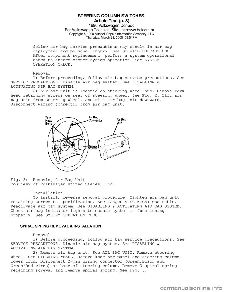
2) Air bag unit is located on steering wheel hub. Remove Torx
head retaining screws on rear of steering wheel. See Fig. 2. Lift air
bag unit from steering wheel, and tilt air bag unit downward.
Disconnect wiring connector from air bag unit.Fig. 2: Removing Air Bag Unit
Courtesy of Volkswagen United States, Inc.
Installation
To install, reverse removal procedure. Tighten air bag unit
retaining screws to specification. See TORQUE SPECIFICATIONS table.
Reactivate air bag system. See DISABLING & ACTIVATING AIR BAG SYSTEM.
Check air bag indicator lights to ensure system is functioning
properly. See SYSTEM OPERATION CHECK.
SPIRAL SPRING REMOVAL & INSTALLATION
Removal
1) Before proceeding, follow air bag service precautions. See
SERVICE PRECAUTIONS. Disable air bag system. See DISABLING &
ACTIVATING AIR BAG SYSTEM.
2) Remove air bag unit. See AIR BAG UNIT. Remove steering
wheel. See STEERING WHEEL. Remove knee bar panel and steering column
lower trim. Disconnect 2-pin wiring connector (Green/Black and
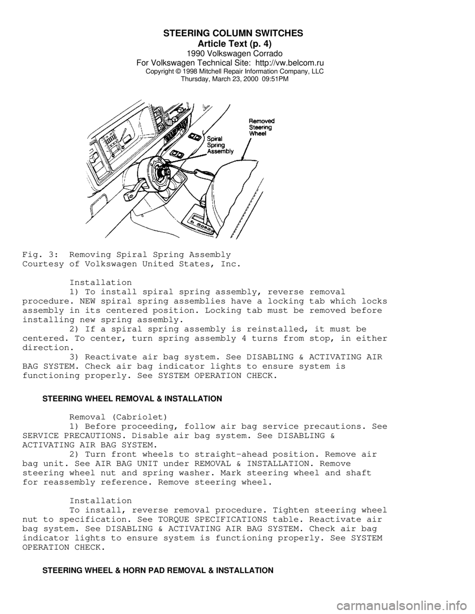
Green/Red wires) at base of steering column. Remove 3 spiral spring
retaining screws, and remove spiral spring. See Fig. 3.
Page 743 of 906
STEERING COLUMN SWITCHES
Article Text (p. 4)
1990 Volkswagen Corrado
For Volkswagen Technical Site: http://vw.belcom.ru
Copyright © 1998 Mitchell Repair Information Company, LLC
Thursday, March 23, 2000 09:51PMFig. 3: Removing Spiral Spring Assembly
Courtesy of Volkswagen United States, Inc.
Installation
1) To install spiral spring assembly, reverse removal
procedure. NEW spiral spring assemblies have a locking tab which locks
assembly in its centered position. Locking tab must be removed before
installing new spring assembly.
2) If a spiral spring assembly is reinstalled, it must be
centered. To center, turn spring assembly 4 turns from stop, in either
direction.
3) Reactivate air bag system. See DISABLING & ACTIVATING AIR
BAG SYSTEM. Check air bag indicator lights to ensure system is
functioning properly. See SYSTEM OPERATION CHECK.
STEERING WHEEL REMOVAL & INSTALLATION
Removal (Cabriolet)
1) Before proceeding, follow air bag service precautions. See
SERVICE PRECAUTIONS. Disable air bag system. See DISABLING &
ACTIVATING AIR BAG SYSTEM.
2) Turn front wheels to straight-ahead position. Remove air
bag unit. See AIR BAG UNIT under REMOVAL & INSTALLATION. Remove
steering wheel nut and spring washer. Mark steering wheel and shaft
for reassembly reference. Remove steering wheel.
Installation
To install, reverse removal procedure. Tighten steering wheel
nut to specification. See TORQUE SPECIFICATIONS table. Reactivate air
bag system. See DISABLING & ACTIVATING AIR BAG SYSTEM. Check air bag
indicator lights to ensure system is functioning properly. See SYSTEM
OPERATION CHECK.
STEERING WHEEL & HORN PAD REMOVAL & INSTALLATION