1990 VOLKSWAGEN CORRADO coolant level
[x] Cancel search: coolant levelPage 20 of 906

* A/C-HEATER SYSTEM UNIFORM INSPECTION GUIDELINES *
Article Text (p. 18)
1990 Volkswagen Corrado
For Volkswagen Technical Site: http://vw.belcom.ru
Copyright © 1998 Mitchell Repair Information Company, LLC
Thursday, March 23, 2000 09:27PMÄÄÄÄÄÄÄÄÄÄÄÄÄÄÄÄÄÄÅÄÄÄÄÄÄÄÄÄÄÄÄÄÄÄÄÄÄÄÄÄÄÅÄÄÄÄÄÄÄÄÄÄÄÄÄÄÄÄÄÄÄÄÄÄÄÄÄÄÄÄAir flow
³ Further inspection ³ If fins cannot be cleaned
obstruction
³ required. ³ or straightened, require
³ ³ replacement.
ÄÄÄÄÄÄÄÄÄÄÄÄÄÄÄÄÄÄÁÄÄÄÄÄÄÄÄÄÄÄÄÄÄÄÄÄÄÄÄÄÄÁÄÄÄÄÄÄÄÄÄÄÄÄÄÄÄÄÄÄÄÄÄÄÄÄÄÄÄÄ HEATER CONTROL VALVE
HEATER CONTROL VALVE
ÄÄÄÄÄÄÄÄÄÄÄÄÄÄÄÄÄÄÄÄÄÄÄÄÄÄÄÄÄÄÄÄÄÄÄÂÄÄÄÄÄÄÄÄÄÄÄÄÄÄÄÄÄÄÄÄÄÄÄÄÄÄÄÄÄÄÄÄÄÄCondition
³ Procedure
ÄÄÄÄÄÄÄÄÄÄÄÄÄÄÄÄÄÄÄÄÄÄÄÄÄÄÄÄÄÄÄÄÄÄÄÅÄÄÄÄÄÄÄÄÄÄÄÄÄÄÄÄÄÄÄÄÄÄÄÄÄÄÄÄÄÄÄÄÄÄCoolant leak
³ Require replacement.
ÄÄÄÄÄÄÄÄÄÄÄÄÄÄÄÄÄÄÄÄÄÄÄÄÄÄÄÄÄÄÄÄÄÄÄÅÄÄÄÄÄÄÄÄÄÄÄÄÄÄÄÄÄÄÄÄÄÄÄÄÄÄÄÄÄÄÄÄÄÄVacuum leak
³ Require replacement.
ÄÄÄÄÄÄÄÄÄÄÄÄÄÄÄÄÄÄÄÄÄÄÄÄÄÄÄÄÄÄÄÄÄÄÄÅÄÄÄÄÄÄÄÄÄÄÄÄÄÄÄÄÄÄÄÄÄÄÄÄÄÄÄÄÄÄÄÄÄÄInoperative
³ Require replacement.
ÄÄÄÄÄÄÄÄÄÄÄÄÄÄÄÄÄÄÄÄÄÄÄÄÄÄÄÄÄÄÄÄÄÄÄÅÄÄÄÄÄÄÄÄÄÄÄÄÄÄÄÄÄÄÄÄÄÄÄÄÄÄÄÄÄÄÄÄÄÄMalfunctioning
³ Suggest replacement.
ÄÄÄÄÄÄÄÄÄÄÄÄÄÄÄÄÄÄÄÄÄÄÄÄÄÄÄÄÄÄÄÄÄÄÄÅÄÄÄÄÄÄÄÄÄÄÄÄÄÄÄÄÄÄÄÄÄÄÄÄÄÄÄÄÄÄÄÄÄÄRestricted
³ Suggest repair or replacement.
ÄÄÄÄÄÄÄÄÄÄÄÄÄÄÄÄÄÄÄÄÄÄÄÄÄÄÄÄÄÄÄÄÄÄÄÁÄÄÄÄÄÄÄÄÄÄÄÄÄÄÄÄÄÄÄÄÄÄÄÄÄÄÄÄÄÄÄÄÄÄ MIX/AIR CONTROL DOORS
MIX/AIR CONTROL DOORS
ÄÄÄÄÄÄÄÄÄÄÄÄÄÄÄÄÄÄÄÄÄÄÄÄÄÄÄÄÄÄÄÄÄÄÄÂÄÄÄÄÄÄÄÄÄÄÄÄÄÄÄÄÄÄÄÄÄÄÄÄÄÄÄÄÄÄÄÄÄÄCondition
³ Procedure
ÄÄÄÄÄÄÄÄÄÄÄÄÄÄÄÄÄÄÄÄÄÄÄÄÄÄÄÄÄÄÄÄÄÄÄÅÄÄÄÄÄÄÄÄÄÄÄÄÄÄÄÄÄÄÄÄÄÄÄÄÄÄÄÄÄÄÄÄÄÄBroken/damaged/binding
³ Require repair or replacement.
ÄÄÄÄÄÄÄÄÄÄÄÄÄÄÄÄÄÄÄÄÄÄÄÄÄÄÄÄÄÄÄÄÄÄÄÅÄÄÄÄÄÄÄÄÄÄÄÄÄÄÄÄÄÄÄÄÄÄÄÄÄÄÄÄÄÄÄÄÄÄDisconnected
³ Require repair or replacement.
ÄÄÄÄÄÄÄÄÄÄÄÄÄÄÄÄÄÄÄÄÄÄÄÄÄÄÄÄÄÄÄÄÄÄÄÁÄÄÄÄÄÄÄÄÄÄÄÄÄÄÄÄÄÄÄÄÄÄÄÄÄÄÄÄÄÄÄÄÄÄ REQUEST FOR MAP MEMBERSHIP INFORMATION
NOTE: To print membership information request form, print portion
of article between dashed lines.
----------------------------------------------------------------------
MAP
Request for Membership Information
I want to be a part of the automotive maintenance and repair
industry's move to improve the level of Customer satisfaction.
Please send me information on how I can become a member of MAP.
Name _________________________________________________________________
Page 101 of 906

* ENGINE SYSTEMS UNIFORM INSPECTION GUIDELINES *
Article Text (p. 4)
1990 Volkswagen Corrado
For Volkswagen Technical Site: http://vw.belcom.ru
Copyright © 1998 Mitchell Repair Information Company, LLC
Thursday, March 23, 2000 09:31PM
Condition ³ Procedure
ÄÄÄÄÄÄÄÄÄÄÄÄÄÄÄÄÄÄÄÄÄÄÅÄÄÄÄÄÄÄÄÄÄÄÄÄÄÄÄÄÄÄÄÄÄÄÄÄÄÄÄÄÄÄÄÄÄÄÄÄÄÄÄÄÄÄÄÄÄÄContaminated
³ Require replacement of oil and filter.
³ See NOTE: (1) below.
ÄÄÄÄÄÄÄÄÄÄÄÄÄÄÄÄÄÄÄÄÄÄÅÄÄÄÄÄÄÄÄÄÄÄÄÄÄÄÄÄÄÄÄÄÄÄÄÄÄÄÄÄÄÄÄÄÄÄÄÄÄÄÄÄÄÄÄÄÄÄHigh level
³ Determine source of incorrect level and
ÄÄÄÄÄÄÄÄÄÄÄÄÄÄÄÄÄÄÄÄÄÄ´ suggest correction.
Low level
³
ÄÄÄÄÄÄÄÄÄÄÄÄÄÄÄÄÄÄÄÄÄÄÅÄÄÄÄÄÄÄÄÄÄÄÄÄÄÄÄÄÄÄÄÄÄÄÄÄÄÄÄÄÄÄÄÄÄÄÄÄÄÄÄÄÄÄÄÄÄÄMaintenance intervals
³ Suggest replacement to comply with vehicles
³ OEM recommended service intervals.
ÄÄÄÄÄÄÄÄÄÄÄÄÄÄÄÄÄÄÄÄÄÄÁÄÄÄÄÄÄÄÄÄÄÄÄÄÄÄÄÄÄÄÄÄÄÄÄÄÄÄÄÄÄÄÄÄÄÄÄÄÄÄÄÄÄÄÄÄÄÄNOTE: (1) Determine source of contamination, i.e., engine coolant,
fuel, metal particles, when changing oil.
ÄÄÄÄÄÄÄÄÄÄÄÄÄÄÄÄÄÄÄÄÄÄÄÄÄÄÄÄÄÄÄÄÄÄÄÄÄÄÄÄÄÄÄÄÄÄÄÄÄÄÄÄÄÄÄÄÄÄÄÄÄÄÄÄÄÄÄÄÄÄENGINE OIL FILTER/CANISTER
ÄÄÄÄÄÄÄÄÄÄÄÄÄÄÄÄÄÄÄÄÄÄÂÄÄÄÄÄÄÄÄÄÄÄÄÄÄÄÄÄÄÄÄÄÄÄÄÄÄÄÄÄÄÄÄÄÄÄÄÄÄÄÄÄÄÄÄÄÄÄCondition
³ Procedure
ÄÄÄÄÄÄÄÄÄÄÄÄÄÄÄÄÄÄÄÄÄÄÅÄÄÄÄÄÄÄÄÄÄÄÄÄÄÄÄÄÄÄÄÄÄÄÄÄÄÄÄÄÄÄÄÄÄÄÄÄÄÄÄÄÄÄÄÄÄÄContaminated
³ Require replacement of oil and filter.
³ See NOTE: (1) below.
ÄÄÄÄÄÄÄÄÄÄÄÄÄÄÄÄÄÄÄÄÄÄÅÄÄÄÄÄÄÄÄÄÄÄÄÄÄÄÄÄÄÄÄÄÄÄÄÄÄÄÄÄÄÄÄÄÄÄÄÄÄÄÄÄÄÄÄÄÄÄDamaged
³ Suggest replacement. Furtherinspection
³ required. See NOTE: (2) below.
ÄÄÄÄÄÄÄÄÄÄÄÄÄÄÄÄÄÄÄÄÄÄÅÄÄÄÄÄÄÄÄÄÄÄÄÄÄÄÄÄÄÄÄÄÄÄÄÄÄÄÄÄÄÄÄÄÄÄÄÄÄÄÄÄÄÄÄÄÄÄLeaking
³ Require repair or replacement.
ÄÄÄÄÄÄÄÄÄÄÄÄÄÄÄÄÄÄÄÄÄÄÅÄÄÄÄÄÄÄÄÄÄÄÄÄÄÄÄÄÄÄÄÄÄÄÄÄÄÄÄÄÄÄÄÄÄÄÄÄÄÄÄÄÄÄÄÄÄÄMaintenance intervals
³ Suggest replacement to comply with vehicles
³ OEM recommended service intervals.
ÄÄÄÄÄÄÄÄÄÄÄÄÄÄÄÄÄÄÄÄÄÄÁÄÄÄÄÄÄÄÄÄÄÄÄÄÄÄÄÄÄÄÄÄÄÄÄÄÄÄÄÄÄÄÄÄÄÄÄÄÄÄÄÄÄÄÄÄÄÄNOTE: (1) Determine cause of contamination, i.e., engine coolant,
fuel, metal particles, when changing oil.
(2) Determine cause, i.e., broken motor mount.
ÄÄÄÄÄÄÄÄÄÄÄÄÄÄÄÄÄÄÄÄÄÄÄÄÄÄÄÄÄÄÄÄÄÄÄÄÄÄÄÄÄÄÄÄÄÄÄÄÄÄÄÄÄÄÄÄÄÄÄÄÄÄÄÄÄÄÄÄÄÄENGINE GASKETS/SEALS
ÄÄÄÄÄÄÄÄÄÄÄÄÄÄÄÄÄÄÄÄÄÄÂÄÄÄÄÄÄÄÄÄÄÄÄÄÄÄÄÄÄÄÄÄÄÄÄÄÄÄÄÄÄÄÄÄÄÄÄÄÄÄÄÄÄÄÄÄÄÄCondition
³ Procedure
ÄÄÄÄÄÄÄÄÄÄÄÄÄÄÄÄÄÄÄÄÄÄÅÄÄÄÄÄÄÄÄÄÄÄÄÄÄÄÄÄÄÄÄÄÄÄÄÄÄÄÄÄÄÄÄÄÄÄÄÄÄÄÄÄÄÄÄÄÄÄLeaking
³ Tighten or suggest replacement as necessary.
ÄÄÄÄÄÄÄÄÄÄÄÄÄÄÄÄÄÄÄÄÄÄÁÄÄÄÄÄÄÄÄÄÄÄÄÄÄÄÄÄÄÄÄÄÄÄÄÄÄÄÄÄÄÄÄÄÄÄÄÄÄÄÄÄÄÄÄÄÄÄENGINE OIL DRAIN PLUG/GASKET
ÄÄÄÄÄÄÄÄÄÄÄÄÄÄÄÄÄÄÄÄÄÄÂÄÄÄÄÄÄÄÄÄÄÄÄÄÄÄÄÄÄÄÄÄÄÄÄÄÄÄÄÄÄÄÄÄÄÄÄÄÄÄÄÄÄÄÄÄÄÄCondition
³ Procedure
ÄÄÄÄÄÄÄÄÄÄÄÄÄÄÄÄÄÄÄÄÄÄÅÄÄÄÄÄÄÄÄÄÄÄÄÄÄÄÄÄÄÄÄÄÄÄÄÄÄÄÄÄÄÄÄÄÄÄÄÄÄÄÄÄÄÄÄÄÄÄLeaking
³ Require repair or replacement.
ÄÄÄÄÄÄÄÄÄÄÄÄÄÄÄÄÄÄÄÄÄÄÅÄÄÄÄÄÄÄÄÄÄÄÄÄÄÄÄÄÄÄÄÄÄÄÄÄÄÄÄÄÄÄÄÄÄÄÄÄÄÄÄÄÄÄÄÄÄÄDamagend threads
³ Require repair or replacement.
ÄÄÄÄÄÄÄÄÄÄÄÄÄÄÄÄÄÄÄÄÄÄÁÄÄÄÄÄÄÄÄÄÄÄÄÄÄÄÄÄÄÄÄÄÄÄÄÄÄÄÄÄÄÄÄÄÄÄÄÄÄÄÄÄÄÄÄÄÄÄNOTE: Some OEMs require replacement of drain plug gasket. Inspect
Page 107 of 906

* ENGINE SYSTEMS UNIFORM INSPECTION GUIDELINES *
Article Text (p. 10)
1990 Volkswagen Corrado
For Volkswagen Technical Site: http://vw.belcom.ru
Copyright © 1998 Mitchell Repair Information Company, LLC
Thursday, March 23, 2000 09:31PMÄÄÄÄÄÄÄÄÄÄÄÄÄÄÄÄÄÄÄÄÄÄÄÄÄÄÄÄÄÄÄÄÄÄÄÅÄÄÄÄÄÄÄÄÄÄÄÄÄÄÄÄÄÄÄÄÄÄÄÄÄÄÄÄÄÄÄÄÄÄMissing, damaged mounting hardware
³ Suggest repair or replacement of
³ hardware.
ÄÄÄÄÄÄÄÄÄÄÄÄÄÄÄÄÄÄÄÄÄÄÄÄÄÄÄÄÄÄÄÄÄÄÄÁÄÄÄÄÄÄÄÄÄÄÄÄÄÄÄÄÄÄÄÄÄÄÄÄÄÄÄÄÄÄÄÄÄÄCOOLANT
ÄÄÄÄÄÄÄÄÄÄÄÄÄÄÄÄÄÄÄÄÄÄÂÄÄÄÄÄÄÄÄÄÄÄÄÄÄÄÄÄÄÄÄÄÄÄÄÄÄÄÄÄÄÄÄÄÄÄÄÄÄÄÄÄÄÄÄÄÄÄCondition
³ Procedure
ÄÄÄÄÄÄÄÄÄÄÄÄÄÄÄÄÄÄÄÄÄÄÅÄÄÄÄÄÄÄÄÄÄÄÄÄÄÄÄÄÄÄÄÄÄÄÄÄÄÄÄÄÄÄÄÄÄÄÄÄÄÄÄÄÄÄÄÄÄÄContaminated
³ Require replacement. Further inspection
³ required. See NOTE: (1).
ÄÄÄÄÄÄÄÄÄÄÄÄÄÄÄÄÄÄÄÄÄÄÅÄÄÄÄÄÄÄÄÄÄÄÄÄÄÄÄÄÄÄÄÄÄÄÄÄÄÄÄÄÄÄÄÄÄÄÄÄÄÄÄÄÄÄÄÄÄÄLow level
³ Require filling to proper level. See
³ NOTE: (2).
ÄÄÄÄÄÄÄÄÄÄÄÄÄÄÄÄÄÄÄÄÄÄÅÄÄÄÄÄÄÄÄÄÄÄÄÄÄÄÄÄÄÄÄÄÄÄÄÄÄÄÄÄÄÄÄÄÄÄÄÄÄÄÄÄÄÄÄÄÄÄImproper mixture/type
³ Require correction or replacement.
ÄÄÄÄÄÄÄÄÄÄÄÄÄÄÄÄÄÄÄÄÄÄÅÄÄÄÄÄÄÄÄÄÄÄÄÄÄÄÄÄÄÄÄÄÄÄÄÄÄÄÄÄÄÄÄÄÄÄÄÄÄÄÄÄÄÄÄÄÄÄImproper acidity (pH)
³ Suggest correction or replacement.
ÄÄÄÄÄÄÄÄÄÄÄÄÄÄÄÄÄÄÄÄÄÄÅÄÄÄÄÄÄÄÄÄÄÄÄÄÄÄÄÄÄÄÄÄÄÄÄÄÄÄÄÄÄÄÄÄÄÄÄÄÄÄÄÄÄÄÄÄÄÄMaintenance intervals
³ Suggest replacement. See NOTE: (3).
ÄÄÄÄÄÄÄÄÄÄÄÄÄÄÄÄÄÄÄÄÄÄÁÄÄÄÄÄÄÄÄÄÄÄÄÄÄÄÄÄÄÄÄÄÄÄÄÄÄÄÄÄÄÄÄÄÄÄÄÄÄÄÄÄÄÄÄÄÄÄNOTE: (1) Determine source of contamination and suggest correction
prior to coolant replacement.
(2) Determine source of incorrect level and suggest repair.
(3) The system should be drained and/or flushed and refilled
with correct coolant according to OEM Recommended Service
Interval and procedure.
ÄÄÄÄÄÄÄÄÄÄÄÄÄÄÄÄÄÄÄÄÄÄÄÄÄÄÄÄÄÄÄÄÄÄÄÄÄÄÄÄÄÄÄÄÄÄÄÄÄÄÄÄÄÄÄÄÄÄÄÄÄÄÄÄÄÄÄÄÄÄWATER PUMP
ÄÄÄÄÄÄÄÄÄÄÄÄÄÄÄÄÄÄÄÄÄÄÄÄÄÄÄÂÄÄÄÄÄÄÄÄÄÄÄÄÄÄÄÄÄÄÄÄÄÄÄÄÄÄÄÄÄÄÄÄÄÄÄÄÄÄÄÄÄÄCondition
³ Procedure
ÄÄÄÄÄÄÄÄÄÄÄÄÄÄÄÄÄÄÄÄÄÄÄÄÄÄÄÅÄÄÄÄÄÄÄÄÄÄÄÄÄÄÄÄÄÄÄÄÄÄÄÄÄÄÄÄÄÄÄÄÄÄÄÄÄÄÄÄÄÄLeaking, damaged
³ Require replacement.
ÄÄÄÄÄÄÄÄÄÄÄÄÄÄÄÄÄÄÄÄÄÄÄÄÄÄÄÅÄÄÄÄÄÄÄÄÄÄÄÄÄÄÄÄÄÄÄÄÄÄÄÄÄÄÄÄÄÄÄÄÄÄÄÄÄÄÄÄÄÄNoisy
³ Suggest replacement.
ÄÄÄÄÄÄÄÄÄÄÄÄÄÄÄÄÄÄÄÄÄÄÄÄÄÄÄÅÄÄÄÄÄÄÄÄÄÄÄÄÄÄÄÄÄÄÄÄÄÄÄÄÄÄÄÄÄÄÄÄÄÄÄÄÄÄÄÄÄÄInoperative
³ Require replacement.
ÄÄÄÄÄÄÄÄÄÄÄÄÄÄÄÄÄÄÄÄÄÄÄÄÄÄÄÅÄÄÄÄÄÄÄÄÄÄÄÄÄÄÄÄÄÄÄÄÄÄÄÄÄÄÄÄÄÄÄÄÄÄÄÄÄÄÄÄÄÄBroken, missing fasteners
³ Require replacement of fasteners.
ÄÄÄÄÄÄÄÄÄÄÄÄÄÄÄÄÄÄÄÄÄÄÄÄÄÄÄÁÄÄÄÄÄÄÄÄÄÄÄÄÄÄÄÄÄÄÄÄÄÄÄÄÄÄÄÄÄÄÄÄÄÄÄÄÄÄÄÄÄÄSHROUD/BAFFLES/DEFLECTORS
ÄÄÄÄÄÄÄÄÄÄÄÄÄÄÄÄÄÄÄÄÄÄÄÄÄÄÄÄÄÄÄÄÄÄÂÄÄÄÄÄÄÄÄÄÄÄÄÄÄÄÄÄÄÄÄÄÄÄÄÄÄÄÄÄÄÄÄÄÄÄCondition
³ Procedure
ÄÄÄÄÄÄÄÄÄÄÄÄÄÄÄÄÄÄÄÄÄÄÄÄÄÄÄÄÄÄÄÄÄÄÅÄÄÄÄÄÄÄÄÄÄÄÄÄÄÄÄÄÄÄÄÄÄÄÄÄÄÄÄÄÄÄÄÄÄÄMissing/damaged
³ Require replacement.
ÄÄÄÄÄÄÄÄÄÄÄÄÄÄÄÄÄÄÄÄÄÄÄÄÄÄÄÄÄÄÄÄÄÄÅÄÄÄÄÄÄÄÄÄÄÄÄÄÄÄÄÄÄÄÄÄÄÄÄÄÄÄÄÄÄÄÄÄÄÄMissing/damaged mounting hardware
³ Require replacement of hardware.
ÄÄÄÄÄÄÄÄÄÄÄÄÄÄÄÄÄÄÄÄÄÄÄÄÄÄÄÄÄÄÄÄÄÄÁÄÄÄÄÄÄÄÄÄÄÄÄÄÄÄÄÄÄÄÄÄÄÄÄÄÄÄÄÄÄÄÄÄÄÄRADIATOR FAN BLADE & FAN CLUTCH
Page 294 of 906

1.8L 4-CYL 8-VALVE & 1.8L 4-CYL 16-VALVE
Article Text (p. 3)
1990 Volkswagen Corrado
For Volkswagen Technical Site: http://vw.belcom.ru
Copyright © 1998 Mitchell Repair Information Company, LLC
Thursday, March 23, 2000 09:40PM
shift as necessary. Evenly tighten mount bolts in reverse order of
loosening. Fill fluids to proper level. Adjust clutch pedal (if
equipped). Tighten all bolts and nuts to specifications.
ENGINE R & I (FOX)
REMOVAL (FOX)
1) Disconnect negative battery cable. Open heater valve,
coolant expansion tank and drain radiator through lower radiator hose.
Mark and disconnect all heater hoses. Disconnect electric cooling fan
and thermo switch. Remove lower and side radiator mounting bolts.
Remove fan, shroud and radiator. Remove M/T clutch cable (if
equipped).
2) Mark and disconnect electrical wiring and vacuum hoses (as
necessary). Disconnect throttle, cruise and kickdown linkage (if
equipped). Remove fuel injectors and install protective caps and
plugs. Leave fuel lines attached and remove cold start valve. Remove
charcoal canister and set aside.
3) Remove 3 upper engine-to-transaxle bolts. Remove intake
air duct. Remove left and right engine mount nuts. Disconnect and
remove starter assembly. Remove 2 lower engine-to-transaxle bolts.
Remove transaxle inspection cover plate. Disconnect exhaust inlet pipe
support and separate inlet pipe from exhaust manifold.
4) Support transaxle. Attach engine sling to engine lifting
hooks. Raise engine/transaxle until engine clears engine mounts.
Ensure transaxle is supported. Remove remaining engine-to-transaxle
bolts. Lift and separate engine from vehicle without transaxle.
INSTALLATION
Lubricate transaxle main shaft splines and contact area
between clutch release bearing and clutch pressure plate with MoS2
grease. DO NOT lubricate guide sleeve for clutch release bearing. To
complete installation, reverse removal procedure. DO NOT reuse self-
locking nuts. Ensure engine mounts are installed to original location.
Tighten engine mounts and subframe bolts with engine running at idle.
Page 443 of 906

D - ADJUSTMENTS
Article Text (p. 6)
1990 Volkswagen Corrado
For Volkswagen Technical Site: http://vw.belcom.ru
Copyright © 1998 Mitchell Repair Information Company, LLC
Thursday, March 23, 2000 09:43PM
NOTE: Before checking engine timing, raise engine speed above 2100
RPM at least 4 times. This must be done each time ignition
is turned off and restarted to clear ECU memory and by-pass
hot-start, fast-idle function.
3) Connect an inductive tachometer or Tester (VW 1367) to
alternator, Test Lead (VW 1473) to ignition coil, and timing light
lead to No. 1 spark plug wire. See Fig. 2. Start engine and ensure
engine speed and timing are correct. If not, adjust to specification.
4) Remove the Blue cap from the CO tap tube rising from the
exhaust manifold and connect exhaust gas analyzer. Disconnect the
coolant sensor harness connector. Raise the oil dipstick slightly to
vent crankcase. Disconnect and plug the crankcase ventilation hose.
Start engine and raise engine speed to 2100 RPM at least 4 times.
Check idle, adjust if incorrect. check CO is correct. See IDLE & CO
LEVEL table. If CO adjustment is needed, the idle mixture screw anti-
tamper plug must be remove from the top of the air flow sensor.
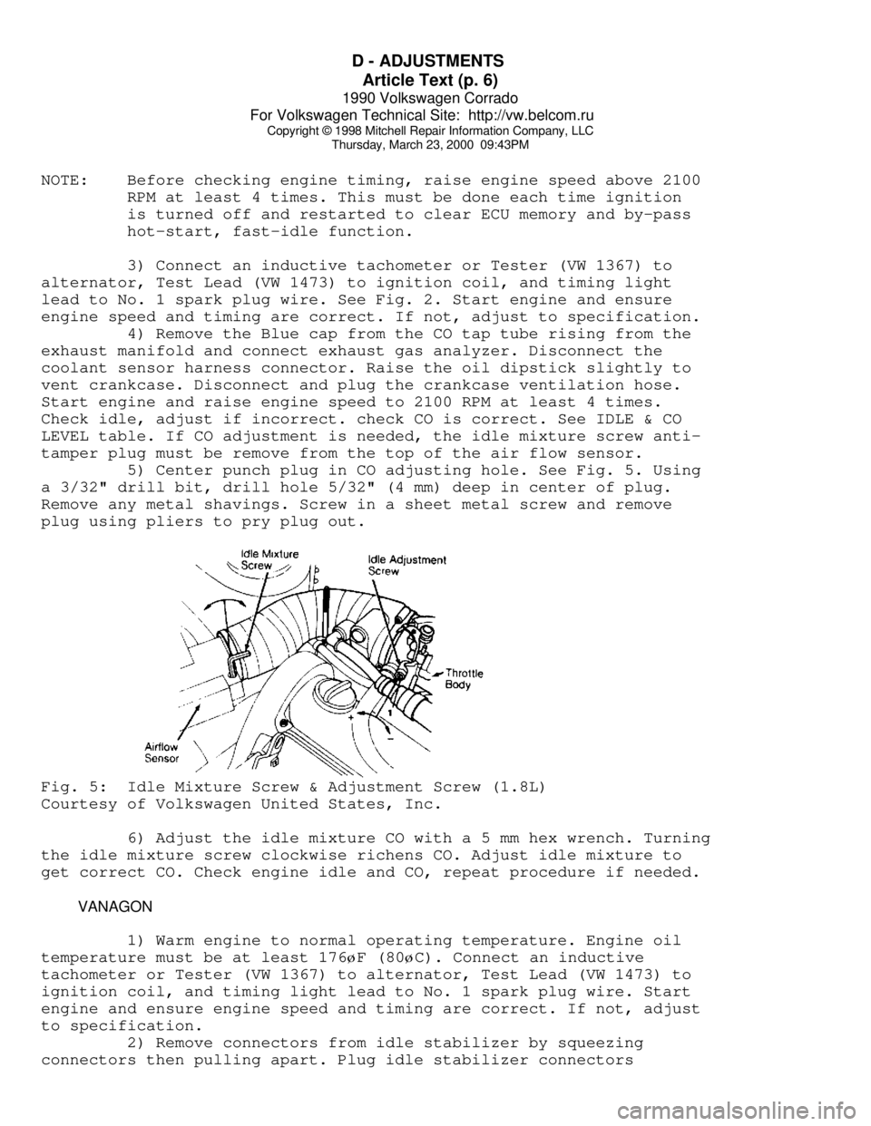
5) Center punch plug in CO adjusting hole. See Fig. 5. Using
a 3/32" drill bit, drill hole 5/32" (4 mm) deep in center of plug.
Remove any metal shavings. Screw in a sheet metal screw and remove
plug using pliers to pry plug out.Fig. 5: Idle Mixture Screw & Adjustment Screw (1.8L)
Courtesy of Volkswagen United States, Inc.
6) Adjust the idle mixture CO with a 5 mm hex wrench. Turning
the idle mixture screw clockwise richens CO. Adjust idle mixture to
get correct CO. Check engine idle and CO, repeat procedure if needed.
VANAGON
1) Warm engine to normal operating temperature. Engine oil
temperature must be at least 176øF (80øC). Connect an inductive
tachometer or Tester (VW 1367) to alternator, Test Lead (VW 1473) to
ignition coil, and timing light lead to No. 1 spark plug wire. Start
engine and ensure engine speed and timing are correct. If not, adjust
to specification.
2) Remove connectors from idle stabilizer by squeezing
connectors then pulling apart. Plug idle stabilizer connectors
Page 453 of 906

E - THEORY/OPERATION - DIGIFANT
Article Text (p. 3)
1990 Volkswagen Corrado
For Volkswagen Technical Site: http://vw.belcom.ru
Copyright © 1998 Mitchell Repair Information Company, LLC
Thursday, March 23, 2000 09:43PM
the following:
* Coolant Temperature Sensor
* ECU Control Relay
* ECU
* Oxygen Sensor
* Power Steering Oil Pressure Switch
NOTE: Components are grouped into 2 categories. The first category
covers INPUT DEVICES, which control or produce voltage
signals monitored by the control unit. The second category
covers OUTPUT SIGNALS, which are components controlled by
the control unit.
INPUT DEVICES
AIRFLOW SENSOR (EXCEPT CORRADO)
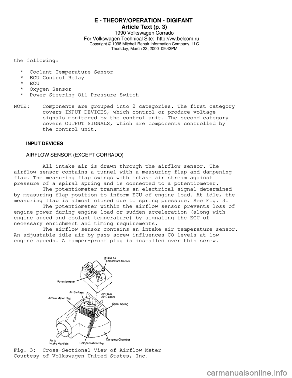
All intake air is drawn through the airflow sensor. The
airflow sensor contains a tunnel with a measuring flap and dampening
flap. The measuring flap swings with intake air stream against
pressure of a spiral spring and is connected to a potentiometer.
The potentiometer transmits an electrical signal determined
by measuring flap position to inform ECU of engine load. At idle, the
measuring flap is almost closed due to spring pressure. See Fig. 3.
The potentiometer within the airflow sensor prevents loss of
engine power during engine load or sudden acceleration (along with
engine speed and coolant temperature) by signaling the ECU of
necessary enrichment and timing requirements.
The airflow sensor contains an intake air temperature sensor.
An adjustable idle air by-pass screw influences CO levels at low
engine speeds. A tamper-proof plug is installed over this screw.Fig. 3: Cross-Sectional View of Airflow Meter
Courtesy of Volkswagen United States, Inc.
Page 476 of 906

ELECTRICAL COMPONENT LOCATOR
Article Text (p. 17)
1990 Volkswagen Corrado
For Volkswagen Technical Site: http://vw.belcom.ru
Copyright © 1998 Mitchell Repair Information Company, LLC
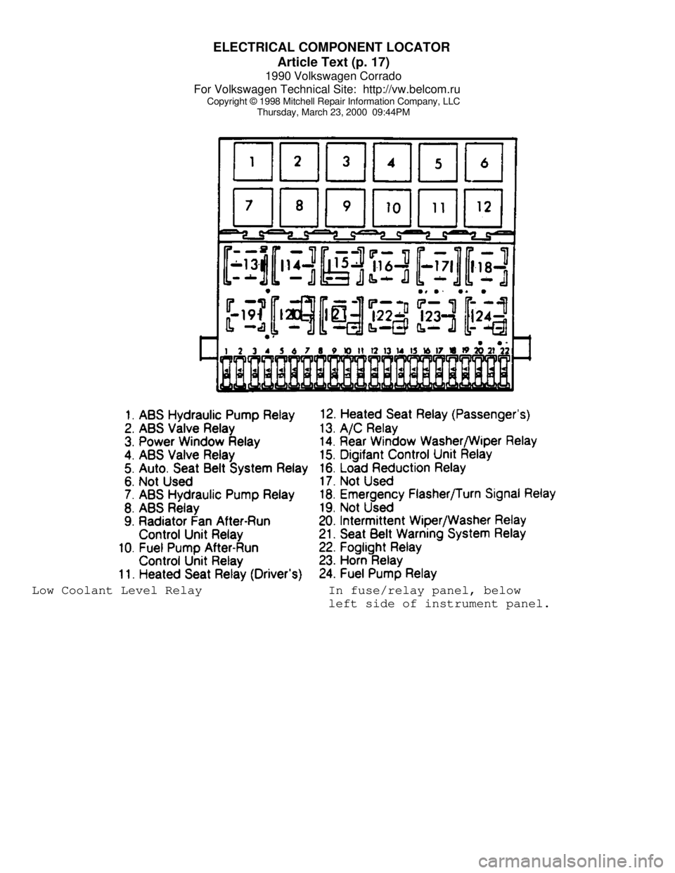
Thursday, March 23, 2000 09:44PMLow Coolant Level Relay In fuse/relay panel, below
left side of instrument panel.
Page 545 of 906

ENGINE OVERHAUL PROCEDURES - GENERAL INFORMATION
Article Text (p. 36)
1990 Volkswagen Corrado
For Volkswagen Technical Site: http://vw.belcom.ru
Copyright © 1998 Mitchell Repair Information Company, LLC
Thursday, March 23, 2000 09:44PM
to ensure correct amount of oil has filled crankcase. Check oil level
while pre-oiling.
If pressure oiler is not available, disconnect ignition
system. Remove oil pressure sending unit and replace with oil pressure
test gauge. Using starter motor, rotate engine starter until gauge
shows normal oil pressure for several seconds. DO NOT crank engine
for more than 30 seconds to avoid starter motor damage.
Ensure oil pressure has reached the most distant point from
the oil pump. Reinstall oil pressure sending unit. Reconnect ignition
system.
INITIAL START-UP
Start the engine and operate engine at low speed while
checking for coolant, fuel and oil leaks. Stop engine. Recheck coolant
and oil level. Adjust if necessary.
CAMSHAFT
Break-in procedure is required when a new or reground
camshaft has been installed. Operate and maintain engine speed between
1500-2500 RPM for approximately 30 minutes. Procedure may vary due to
manufacturers recommendations.
PISTON RINGS
Piston rings require a break-in procedure to ensure seating
of rings to cylinder walls. Serious damage may occur to rings if
correct procedures are not followed.
Extremely high piston ring temperatures are produced obtained
during break-in process. If rings are exposed to excessively high RPM
or high cylinder pressures, ring damage can occur. Follow piston ring
manufacturer's recommended break-in procedure.
FINAL ADJUSTMENTS
Check or adjust ignition timing and dwell (if applicable).
Adjust valves (if necessary). Adjust carburetion or injection idle
speed and mixture. Retighten cylinder heads (if required). If
cylinder head or block is aluminum, retighten bolts when engine is
cold. Follow the engine manufacturer's recommended break-in procedure
and maintenance schedule for new engines.
NOTE: Some manufacturer's require that head bolts be retightened
after specified amount of operation. This must be done to
prevent head gasket failure.
END OF ARTICLE