1990 VOLKSWAGEN CORRADO jump start
[x] Cancel search: jump startPage 412 of 906

ANTI-LOCK BRAKE SYSTEM
Article Text (p. 4)
1990 Volkswagen Corrado
For Volkswagen Technical Site: http://vw.belcom.ru
Copyright © 1998 Mitchell Repair Information Company, LLC
Thursday, March 23, 2000 09:42PM
seconds maximum and then stop. Depress brake pedal a few times; pump
should operate again for a few seconds. If pump motor does not
operate, check electrical system. If pump motor operates for more than
60 seconds, internal or external hydraulic leak may be indicated.
Check for external leaks. If external leak is not found, further
testing may be needed to check for internal leaks.
ANTI-LOCK WARNING LIGHT
Start engine. ANTI-LOCK warning light should come on, then
turn off after a few seconds. If light does not come on when engine is
started, check electrical system. If light comes on and stays on,
fault has been detected by the ECU and testing will be needed. See
SYSTEM TESTING under DIAGNOSIS & TESTING.
DIAGNOSIS & TESTING
SYSTEM TESTING
NOTE: Check battery condition, brake fluid level, electrical
connections and wiring for damage. If fluid level is
incorrect or battery and/or electrical connections are
faulty, correct problem before preceding. Perform each step,
in sequence, to test entire system, except for ECU. If
faulty ECU is suspected, replace with a known good one, and
retest system. Unplug ECU connector for all test steps.
Power Voltage-To-ECU Test
Turn ignition off. Unplug ECU connector. Turn ignition on.
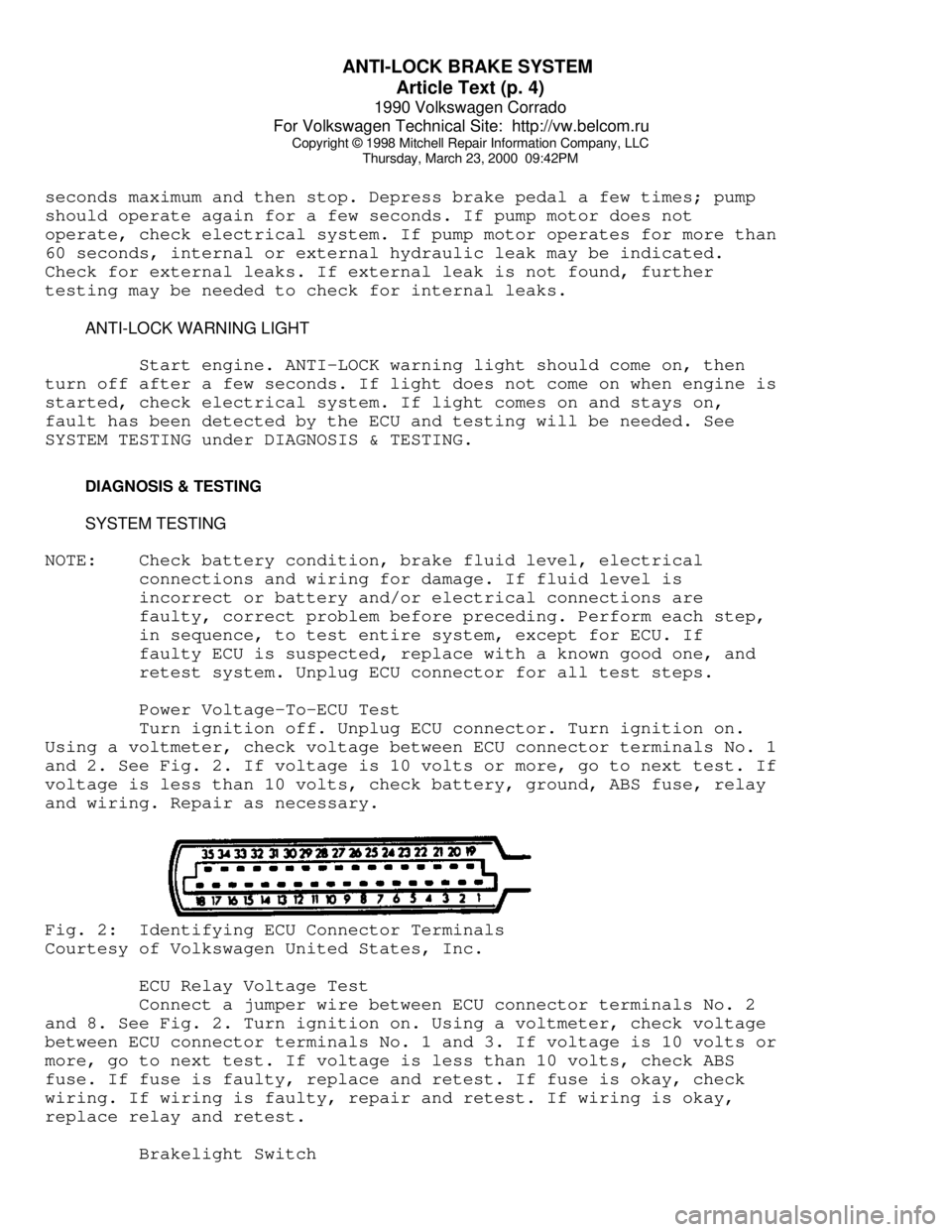
Using a voltmeter, check voltage between ECU connector terminals No. 1
and 2. See Fig. 2. If voltage is 10 volts or more, go to next test. If
voltage is less than 10 volts, check battery, ground, ABS fuse, relay
and wiring. Repair as necessary.Fig. 2: Identifying ECU Connector Terminals
Courtesy of Volkswagen United States, Inc.
ECU Relay Voltage Test
Connect a jumper wire between ECU connector terminals No. 2
and 8. See Fig. 2. Turn ignition on. Using a voltmeter, check voltage
between ECU connector terminals No. 1 and 3. If voltage is 10 volts or
more, go to next test. If voltage is less than 10 volts, check ABS
fuse. If fuse is faulty, replace and retest. If fuse is okay, check
wiring. If wiring is faulty, repair and retest. If wiring is okay,
replace relay and retest.
Brakelight Switch
Page 550 of 906

F - BASIC TESTING
Article Text (p. 5)
1990 Volkswagen Corrado
For Volkswagen Technical Site: http://vw.belcom.ru
Copyright © 1998 Mitchell Repair Information Company, LLC
Thursday, March 23, 2000 09:44PM
to OFF position.
(2) - With pressure regulator vacuum hose disconnected, pressure
should be 36 psi (2.5 kg/cmý).
ÄÄÄÄÄÄÄÄÄÄÄÄÄÄÄÄÄÄÄÄÄÄÄÄÄÄÄÄÄÄÄÄÄÄÄÄÄÄÄÄÄÄÄÄÄÄÄÄÄÄÄÄÄÄÄÄÄÄÄÄÄÄÄÄÄÄÄÄÄÄ TRANSFER PUMP CHECK
TRANSFER PUMP FUEL VOLUME CHECK
1) Turn ignition off. To check transfer pump (in tank),
remove rear seat. Remove fuel sending unit access cover. Disconnect
ignition coil secondary wire and jumper to ground. With transmission
in neutral, crank engine for a 3-4 seconds. While the starter is
turning and for a few seconds afterwards, an audible sound should be
heard at the pump. If not, proceed to step 2).
2) Activate fuel pumps by removing fuel pump relay and
attaching jumper wire between terminals No. 30 battery voltage and No.
87 output to fuel pumps. Terminal identification is molded on
fuse/relay panel. If pump does not operate, remove transfer pump
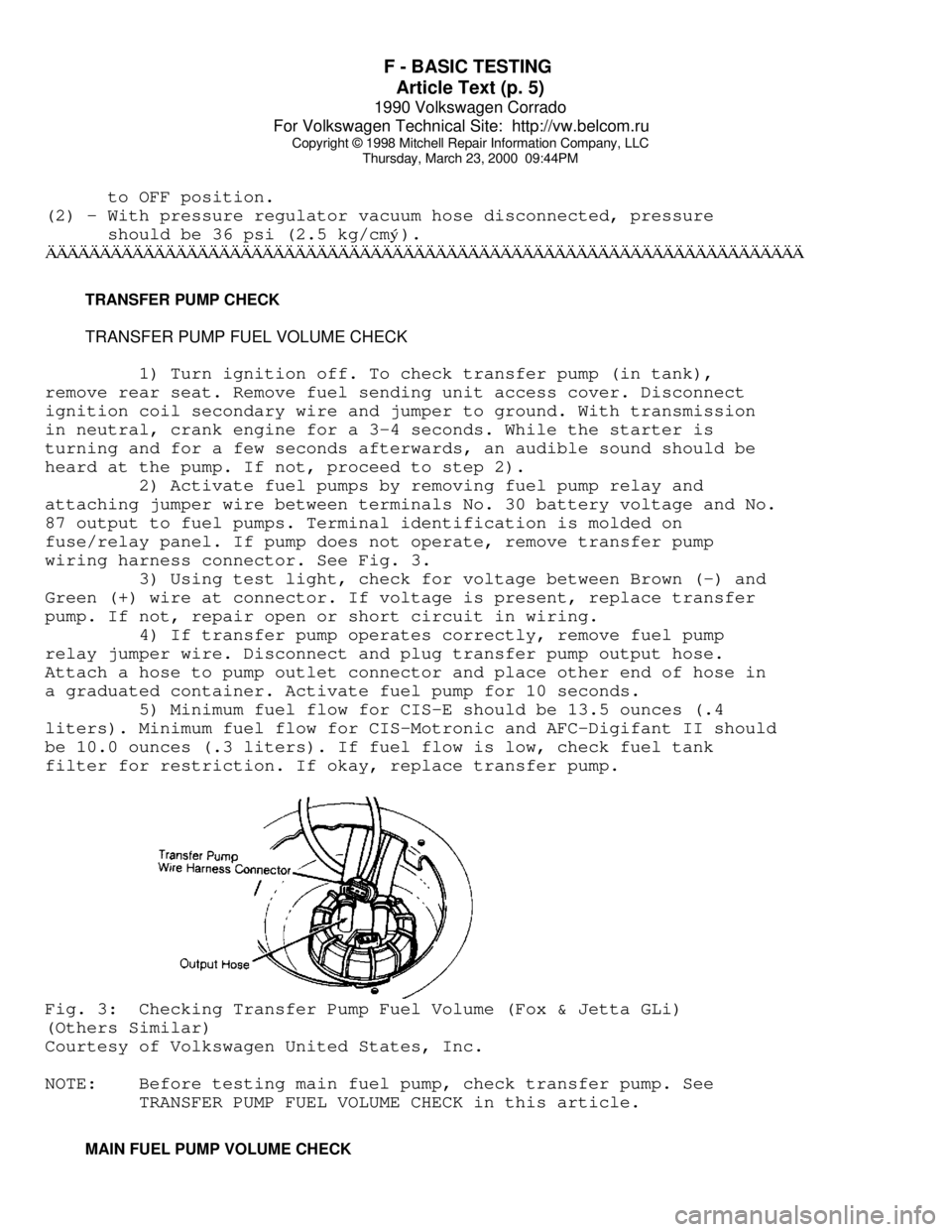
wiring harness connector. See Fig. 3.
3) Using test light, check for voltage between Brown (-) and
Green (+) wire at connector. If voltage is present, replace transfer
pump. If not, repair open or short circuit in wiring.
4) If transfer pump operates correctly, remove fuel pump
relay jumper wire. Disconnect and plug transfer pump output hose.
Attach a hose to pump outlet connector and place other end of hose in
a graduated container. Activate fuel pump for 10 seconds.
5) Minimum fuel flow for CIS-E should be 13.5 ounces (.4
liters). Minimum fuel flow for CIS-Motronic and AFC-Digifant II should
be 10.0 ounces (.3 liters). If fuel flow is low, check fuel tank
filter for restriction. If okay, replace transfer pump.Fig. 3: Checking Transfer Pump Fuel Volume (Fox & Jetta GLi)
(Others Similar)
Courtesy of Volkswagen United States, Inc.
NOTE: Before testing main fuel pump, check transfer pump. See
TRANSFER PUMP FUEL VOLUME CHECK in this article.
MAIN FUEL PUMP VOLUME CHECK
Page 590 of 906

I - SYSTEM/COMPONENT TESTS
Article Text (p. 3)
1990 Volkswagen Corrado
For Volkswagen Technical Site: http://vw.belcom.ru
Copyright © 1998 Mitchell Repair Information Company, LLC
Thursday, March 23, 2000 09:46PM
circuits to ECU. The ECU engine ground is near ignition distributor.
Remove ECU connector. Check resistance to ground on terminal No. 35.
Resistance should be zero ohms. If resistance is not zero ohms, repair
open or short in wiring.
POWER CIRCUITS
Turn ignition off. Disconnect ECU connector. Using a
voltmeter, check terminals No. 12, 14, 19 and 34 for battery voltage.
If battery voltage is not present. Check fuses No. 15, 18 and 24. If
fuses are okay, check for open in wiring between ECU and fuse box. See
L - WIRING DIAGRAMS for terminal identification and wire colors.
ENGINE SENSORS & SWITCHES
AIRFLOW SENSOR (FOX & JETTA GLI)
1) Start engine to pressurized fuel system. Turn engine off
and remove intake boot from top of airflow sensor. Disconnect coil
secondary wire from coil and jumper to ground.
2) Check sensor play by slowly moving sensor plate through
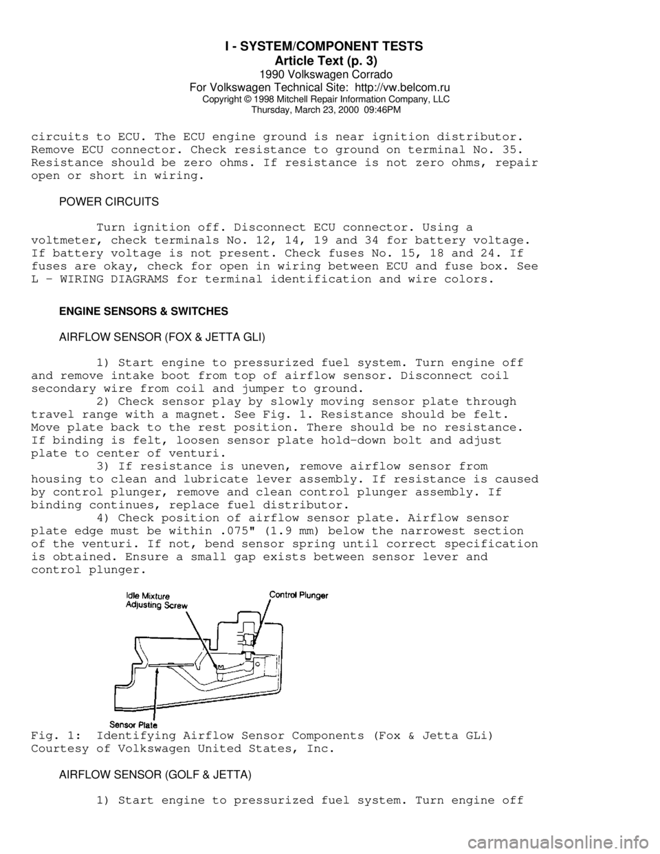
travel range with a magnet. See Fig. 1. Resistance should be felt.
Move plate back to the rest position. There should be no resistance.
If binding is felt, loosen sensor plate hold-down bolt and adjust
plate to center of venturi.
3) If resistance is uneven, remove airflow sensor from
housing to clean and lubricate lever assembly. If resistance is caused
by control plunger, remove and clean control plunger assembly. If
binding continues, replace fuel distributor.
4) Check position of airflow sensor plate. Airflow sensor
plate edge must be within .075" (1.9 mm) below the narrowest section
of the venturi. If not, bend sensor spring until correct specification
is obtained. Ensure a small gap exists between sensor lever and
control plunger.Fig. 1: Identifying Airflow Sensor Components (Fox & Jetta GLi)
Courtesy of Volkswagen United States, Inc.
AIRFLOW SENSOR (GOLF & JETTA)
1) Start engine to pressurized fuel system. Turn engine off
Page 597 of 906

I - SYSTEM/COMPONENT TESTS
Article Text (p. 10)
1990 Volkswagen Corrado
For Volkswagen Technical Site: http://vw.belcom.ru
Copyright © 1998 Mitchell Repair Information Company, LLC
Thursday, March 23, 2000 09:46PM
FUEL CONTROL
COLD START VALVE (ALL MODELS EXCEPT VANAGON)
1) Engine temperature must be below 85øF (30øC). Disconnect
cold start valve attaching screws and remove valve with harness
connector and fuel line attached.
2) Remove ignition coil secondary wire and jumper to ground.
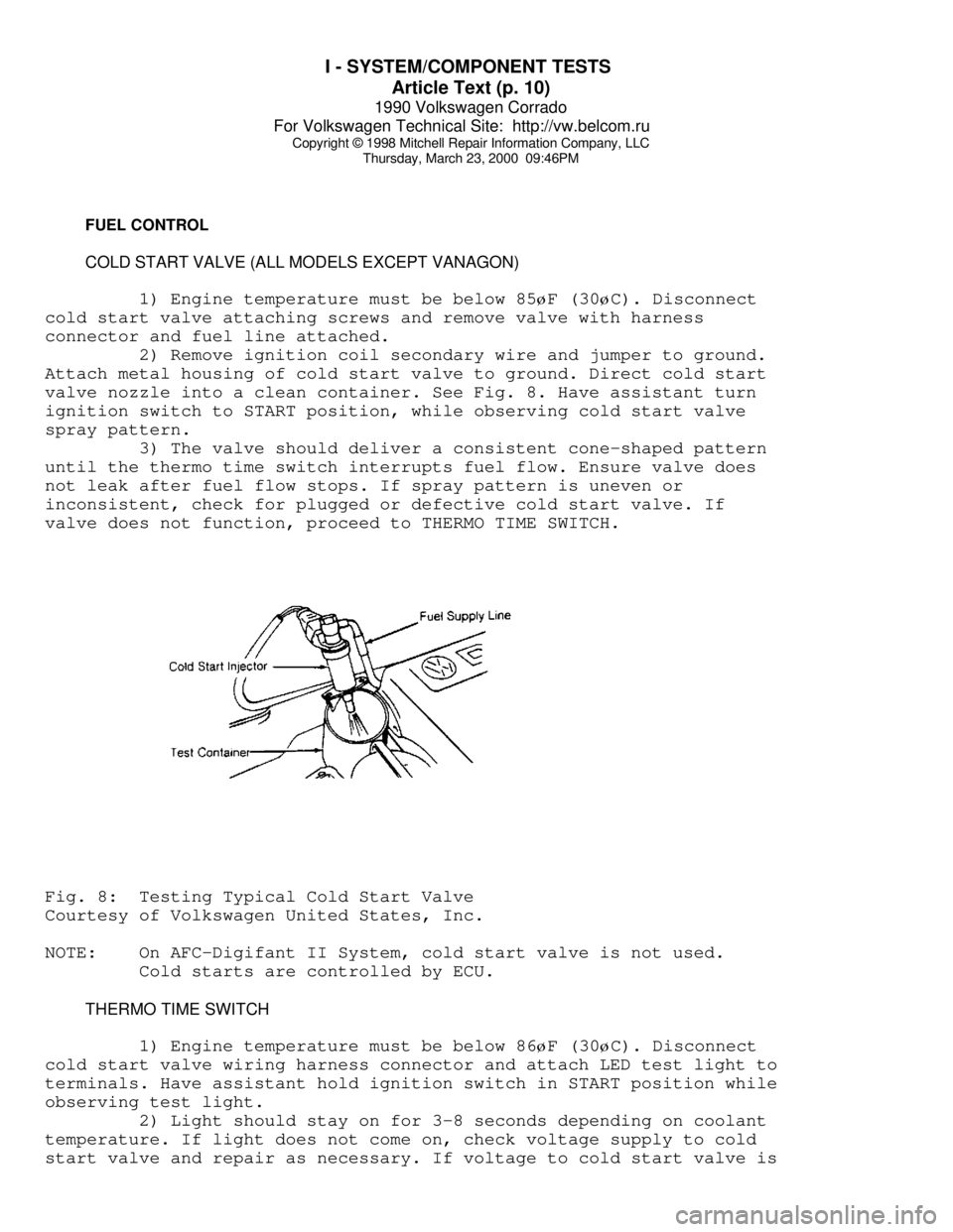
Attach metal housing of cold start valve to ground. Direct cold start
valve nozzle into a clean container. See Fig. 8. Have assistant turn
ignition switch to START position, while observing cold start valve
spray pattern.
3) The valve should deliver a consistent cone-shaped pattern
until the thermo time switch interrupts fuel flow. Ensure valve does
not leak after fuel flow stops. If spray pattern is uneven or
inconsistent, check for plugged or defective cold start valve. If
valve does not function, proceed to THERMO TIME SWITCH.Fig. 8: Testing Typical Cold Start Valve
Courtesy of Volkswagen United States, Inc.
NOTE: On AFC-Digifant II System, cold start valve is not used.
Cold starts are controlled by ECU.
THERMO TIME SWITCH
1) Engine temperature must be below 86
øF (30øC). Disconnect
cold start valve wiring harness connector and attach LED test light to
terminals. Have assistant hold ignition switch in START position while
observing test light.
2) Light should stay on for 3-8 seconds depending on coolant
temperature. If light does not come on, check voltage supply to cold
start valve and repair as necessary. If voltage to cold start valve is
Page 598 of 906

I - SYSTEM/COMPONENT TESTS
Article Text (p. 11)
1990 Volkswagen Corrado
For Volkswagen Technical Site: http://vw.belcom.ru
Copyright © 1998 Mitchell Repair Information Company, LLC
Thursday, March 23, 2000 09:46PM
okay, check ground circuit through thermo time switch. Replace thermo
time switch if contact to ground cannot be made.
IDLE CONTROL SYSTEM
NOTE: Knock control is integral in AFC-Digifant II ECU.
KNOCK SENSOR CONTROL UNIT (ALL MODELS EXCEPT VANAGON)
1) Check ignition coil and Hall Effect sender before checking
knock sensor control unit. Remove knock sensor control unit harness
connector. Turn ignition on. Using a voltmeter, check for battery
voltage between terminals No. 3 and No. 5 and terminals No. 6 and No.
3 of knock sensor control unit. Open throttle valve. Voltage should
drop to zero volts.
2) If voltage does not drop to zero volts, check throttle
valve switch (full throttle). Check voltage between terminals No. 8
and No. 3, while fully opening throttle valve. If battery voltage was
not present when throttle fully open, replace throttle valve switch.
See Fig. 13.
3) Remove Hall Effect sender connector and connect voltmeter
to outside terminals. Turn ignition on. There should be 5 volts
present. Turn ignition off. Connect voltmeter between terminals No. 1
(negative) and No. 15 (positive) of ignition coil. Turn ignition on
and touch center terminal of Hall Effect sender briefly to ground.
Voltage should jump momentarily to approximately 2 volts. If voltage
does not jump, replace knock sensor control unit.
KNOCK SENSOR(S)
Before replacing knock sensor, check knock sensor torque and
resistance. Remove knock sensor connector and check resistance between
terminals No. 13 and No. 14. See KNOCK SENSOR TORQUE & RESISTANCE
SPECIFICATION table. If resistance is incorrect, replace knock sensor.
NOTE: Knock sensor mounting bolt torque must be exact. DO NOT use
washers when mounting knock sensor.
KNOCK SENSOR RESISTANCE & TORQUE SPECIFICATIONÄÄÄÄÄÄÄÄÄÄÄÄÄÄÄÄÄÄÄÄÄÄÄÄÄÄÄÄÄÄÄÄÄÄÄÄÄÄÄÄÄÄÄÄÄÄÄÄÄÄÄÄÄÄÄÄÄÄÄÄÄÄÄÄÄÄÄÄÄÄApplication Resistance Ft. Lbs (N.m)
Type I ...................... 300,000 ................ 7-9 (10-12)
Type II .................... Infinite .............. 15-18 (20-25)
ÄÄÄÄÄÄÄÄÄÄÄÄÄÄÄÄÄÄÄÄÄÄÄÄÄÄÄÄÄÄÄÄÄÄÄÄÄÄÄÄÄÄÄÄÄÄÄÄÄÄÄÄÄÄÄÄÄÄÄÄÄÄÄÄÄÄÄÄÄÄ IDLE STABILIZATION SYSTEM (VANAGON)
1) Attach Test Meter (VW 1315/2) and Adapter (US 1119) to
idle stabilization valve. Set meter to milliampere scale. Start
engine. Observe test meter while turning A/C control switch to ON
position. If milliampere reading increases, system is okay.
Page 678 of 906

N - REMOVE/INSTALL/OVERHAUL
Article Text (p. 5)
1990 Volkswagen Corrado
For Volkswagen Technical Site: http://vw.belcom.ru
Copyright © 1998 Mitchell Repair Information Company, LLC
Thursday, March 23, 2000 09:49PM
distributor. Install fuel distributor. See TORQUE SPECIFICATIONS for
tightening specifications. Connect all fuel lines except those to fuel
injectors. Check sensor plate adjusting lever and fuel distributor
control piston for smooth operation.
2) Remove fuel pump relay and bridge fuel pump circuit. Use
Jumper Switch (US 4480/3) in place of fuel pump relay. When pressure
has built up, turn off fuel pump. Move sensor plate from rest position
to end of travel.
3) Uniform resistance should be felt during entire movement.
No resistance should be felt during entire movement. No resistance
should be felt on quick return to rest position. Connect injector
lines. Install fuel pump relay. Start engine and check for leaks.
INJECTORS (DIGIFANT)
CAUTION: Fuel system pressure must be relieved before removing
injectors. Wipe up all spilled fuel BEFORE continuing
service.
Removal (AFC-Digifant II)
Disconnect negative battery cable. Disconnect main electrical
connector from fuel rail. Remove idle stabilizer valve. Loosen and
remove both hoses on each end of fuel rail. Remove fuel pressure
regulator and mounting bracket. Remove fuel rail mounting bolts. Pry
off injector mounting clips. Disconnect injector electrical
connectors. Remove fuel rail. Remove each injector from its insert.
Installation
To install injectors, reverse removal procedures. Use new "O"
rings when installing injectors. Replace hose clamps if necessary. See
TORQUE SPECIFICATIONS table at end of this article. Check for fuel
leaks.
INJECTORS (CIS SYSTEMS)
Removal (CIS-E & CIS-E Motronic)
Remove injectors from inserts in cylinder head with fuel
lines attached. Using 12-mm or 13-mm hex wrench, remove inserts from
head. Use 2 wrenches to remove injectors from fuel lines.
Installation
To install, reverse removal procedures. Use 2 wrenches when
tightening injector lines to injectors. Use new "O" rings lightly
lubricated. On models with 2-piece inserts, replace insert sealing
washer (against head) and use sealing compound on upper insert
threaded portion. See TORQUE SPECIFICATIONS.
OXYGEN (O2) SENSOR
Removal & Installation
Oxygen (O2) sensor is mounted in the exhaust pipe in front of
catalytic converter. Disconnect permanent pigtail from sensor. Ensure