1990 VOLKSWAGEN CORRADO key battery
[x] Cancel search: key batteryPage 436 of 906

COMPUTER RELEARN PROCEDURES
Article Text
1990 Volkswagen Corrado
For Volkswagen Technical Site: http://vw.belcom.ru
Copyright © 1998 Mitchell Repair Information Company, LLC
Thursday, March 23, 2000 09:43PM
ARTICLE BEGINNING
GENERAL INFORMATION
Computer Relearn Procedures
All Models
* PLEASE READ THIS FIRST *
The following general procedures are to be used if
driveability problems are encountered after power loss or battery has
been disconnected. These procedures may provide an aid in eliminating
these problems.
To reduce the possibility of complaints, after any service
which requires battery power to be disconnected, vehicle should be
road tested.
COMPUTER RELEARN PROCEDURES
Vehicles equipped with engine or transmission computers may
require a relearn procedure after vehicle battery is disconnected.
Many vehicle computers memorize and store vehicle operation patterns
for optimum driveability and performance. When vehicle battery is
disconnected, this memory is lost. The computer will use default data
until new data from each key start is stored. As computer memorizes
vehicle operation for each new key start, driveability is restored.
Vehicle computers may memorize vehicles operation patterns for 40 of
more key starts.
Customers often complain of driveability problems during
relearn stage because vehicle acts differently then before being
serviced. Depending on type and make of vehicle and how it is
equipped, the following complaints (driveability problems) may exist:
* Harsh Or Poor Shift Quality
* Rough Or Unstable Idle
* Hesitation Or Stumble
* Rich Or Lean Running
* Poor Fuel Mileage
These symptoms and complaints should disappear after a number
of drive cycles have been memorized. To reduce the possibility of
complaints, after any service which requires battery power to be
disconnected, vehicle should be road tested. If a specific relearn
procedure is not available, the following procedure may be used:
Automatic Transmission
* Set parking brake, start engine in "P" or "N" position.
Warm-up vehicle to normal operating temperature or until
cooling fan cycles.
* Allow vehicle to idle for one minute in "N" position. Select
Page 565 of 906

FUSES & CIRCUIT BREAKERS
Article Text (p. 3)
1990 Volkswagen Corrado
For Volkswagen Technical Site: http://vw.belcom.ru
Copyright © 1998 Mitchell Repair Information Company, LLC
Thursday, March 23, 2000 09:45PM
start at any time even when the ignition key is in the OFF
position. DO NOT loosen or remove radiator cap when cooling
system is hot.
REPLACING BLOWN FUSES
Before replacing a blown fuse, remove ignition key, turn off
all lights and accessories to avoid damaging the electrical system. Be
sure to use fuse with the correct indicated amperage rating. The use
of an incorrect amperage rating fuse may result in a dangerous
electrical system overload.
BATTERY WARNING
WARNING: When battery is disconnected, vehicles equipped with
computers may lose memory data. When battery power is
restored, driveability problems may exist on some vehicles.
These vehicles may require a relearn procedure. See COMPUTER
RELEARN PROCEDURES article in GENERAL INFORMATION section.
BRAKE PAD WEAR INDICATOR
Indicator will cause a squealing or scraping noise, warning
that brake pads need replacement.
HALOGEN BULBS
Halogen bulbs contain pressurized gas which may explode if
overheated. DO NOT touch glass portion of bulb with bare hands. Eye
protection should be worn when handling or working around halogen
bulbs.
SUPPLEMENTAL RESTRAINT SYSTEM (AIR BAG)
NOTE: See the AIR BAGS article in the ACCESSORIES/SAFETY EQUIPMENT
Section.
Modifications or improper maintenance, including incorrect
removal and installation of the Supplemental Restraint System (SRS),
can adversely affect system performance. DO NOT cover, obstruct or
change the steering wheel horn pad in any way, as such action could
cause improper function of the system. Use only plain water when
cleaning the horn pad. Solvents or cleaners could adversely affect the
air bag cover and cause improper deployment of the system.
WARNING: To avoid injury from accidental air bag deployment, read and
carefully follow all warnings and service precautions. See
appropriate AIR BAGS article in ACCESSORIES/SAFETY EQUIPMENT.
CAUTION: Disconnect negative battery cable before servicing any air
bag system, steering column or passenger side dash
component. After any repair, turn ignition key to the ON
Page 684 of 906

SCHEDULED SERVICES
Article Text
1990 Volkswagen Corrado
For Volkswagen Technical Site: http://vw.belcom.ru
Copyright © 1998 Mitchell Repair Information Company, LLC
Thursday, March 23, 2000 09:49PM
ARTICLE BEGINNING
1990-94 MAINTENANCE
Volkswagen Maintenance & Service Intervals
Corrado G60 (1990-92)
SLC (1992-94 USA)
VR6 (1992-94 Canada)
* PLEASE READ THIS FIRST *
NOTE: All SERVICE SCHEDULES are listed for normal service
vehicles. If vehicle is operated under severe service
conditions, see SEVERE SERVICE REQUIREMENTS (PERFORM
W/SERVICE SCHEDULES) for items requiring additional
maintenance.
NOTE: This article contains scheduled maintenance service
information. Fluid types and capacities listed with each
service in this article are only those necessary to perform
that scheduled service. For specifications pertaining to
fluid capacities for the entire vehicle, fuse and circuit
breaker identification, wheel and tire size, battery type,
warranty information, or model identification refer to the
MAINTENANCE INFORMATION article in this section.
CAUTIONS & WARNINGS
SUPPLEMENTAL RESTRAINT SYSTEM (AIR BAG) - 1995 MODELS
NOTE: See the AIR BAGS article in the ACCESSORIES/SAFETY EQUIPMENT
Section.
Modifications or improper maintenance, including incorrect
removal and installation of the Supplemental Restraint System (SRS),
can adversely affect system performance. DO NOT cover, obstruct or
change the steering wheel horn pad in any way, as such action could
cause improper function of the system. Use only plain water when
cleaning the horn pad. Solvents or cleaners could adversely affect the
air bag cover and cause improper deployment of the system.
WARNING: To avoid injury from accidental air bag deployment, read and
carefully follow all warnings and service precautions. See
appropriate AIR BAGS article in ACCESSORIES/SAFETY EQUIPMENT.
CAUTION: Disconnect negative battery cable before servicing any air
bag system, steering column or passenger side dash
component. After any repair, turn ignition key to the ON
position from passenger's side of vehicle in case of
accidental air bag inflation
Page 737 of 906
STEERING COLUMN
Article Text (p. 3)
1990 Volkswagen Corrado
For Volkswagen Technical Site: http://vw.belcom.ru
Copyright © 1998 Mitchell Repair Information Company, LLC
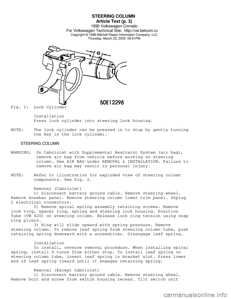
Thursday, March 23, 2000 09:51PMFig. 1: Lock Cylinder
Installation
Press lock cylinder into steering lock housing.
NOTE: The lock cylinder can be pressed in to stop by gently turning
the key in the lock cylinder.
STEERING COLUMN
WARNING: On Cabriolet with Supplemental Restraint System (air bag),
remove air bag from vehicle before working on steering
column. See AIR BAG under REMOVAL & INSTALLATION. Failure to
remove air bag may result in personal injury.
NOTE: Refer to illustration for exploded view of steering column
components. See Fig. 2.
Removal (Cabriolet)
1) Disconnect battery ground cable. Remove steering wheel.
Remove kneebar panel. Remove steering column lower trim panel. Unplug
2 electrical connectors.
2) Remove spiral spring assembly retaining screws. Remove
lock ring, spacer ring, spring and steering lock housing. Position
Tube (VW 420) on steering column. Release lock ring tension using snap
ring pliers.
3) Ring will slide upward with spring pressure. Remove
steering column. To remove leaf spring from steering column tube, push
retaining spring downward with a screwdriver. Disengage leaf spring.
Installation
To install, reverse removal procedure. When installing spiral
spring, install 4 turns from either stop. To install leaf spring on
steering column tube, insert leaf spring in bracket slot. Press lower
end of leaf spring inward until it engages retaining spring.
Removal (Except Cabriolet)
1) Disconnect battery ground cable. Remove steering wheel.
Remove bolt and screw from switch housing recess. Tilt switch unit