1990 VOLKSWAGEN CORRADO timing belt
[x] Cancel search: timing beltPage 102 of 906

* ENGINE SYSTEMS UNIFORM INSPECTION GUIDELINES *
Article Text (p. 5)
1990 Volkswagen Corrado
For Volkswagen Technical Site: http://vw.belcom.ru
Copyright © 1998 Mitchell Repair Information Company, LLC
Thursday, March 23, 2000 09:31PM
threads in oil pan for damage.ÄÄÄÄÄÄÄÄÄÄÄÄÄÄÄÄÄÄÄÄÄÄÄÄÄÄÄÄÄÄÄÄÄÄÄÄÄÄÄÄÄÄÄÄÄÄÄÄÄÄÄÄÄÄÄÄÄÄÄÄÄÄÄÄÄÄÄÄÄÄENGINE OIL WARNING LIGHTS
ÄÄÄÄÄÄÄÄÄÄÄÄÄÄÄÄÄÄÄÄÄÄÄÄÄÄÄÄÄÄÄÂÄÄÄÄÄÄÄÄÄÄÄÄÄÄÄÄÄÄÄÄÄÄÄÄÄÄÄÄÄÄÄÄÄÄÄÄÄÄCondition
³ Procedure
ÄÄÄÄÄÄÄÄÄÄÄÄÄÄÄÄÄÄÄÄÄÄÄÄÄÄÄÄÄÄÄÅÄÄÄÄÄÄÄÄÄÄÄÄÄÄÄÄÄÄÄÄÄÄÄÄÄÄÄÄÄÄÄÄÄÄÄÄÄÄLight not on during bulb check
³ Further inspection required. See
³ NOTE: below.
ÄÄÄÄÄÄÄÄÄÄÄÄÄÄÄÄÄÄÄÄÄÄÄÄÄÄÄÄÄÄÄÅÄÄÄÄÄÄÄÄÄÄÄÄÄÄÄÄÄÄÄÄÄÄÄÄÄÄÄÄÄÄÄÄÄÄÄÄÄÄLight stays on or intermittent
³ Further inspection required. See
while engine is running
³ NOTE: below.
ÄÄÄÄÄÄÄÄÄÄÄÄÄÄÄÄÄÄÄÄÄÄÄÄÄÄÄÄÄÄÄÅÄÄÄÄÄÄÄÄÄÄÄÄÄÄÄÄÄÄÄÄÄÄÄÄÄÄÄÄÄÄÄÄÄÄÄÄÄÄNOTE: Light may indicate problem with contaminated oil, level,
pressure, temperature or problem with circuit.
ÄÄÄÄÄÄÄÄÄÄÄÄÄÄÄÄÄÄÄÄÄÄÄÄÄÄÄÄÄÄÄÄÄÄÄÄÄÄÄÄÄÄÄÄÄÄÄÄÄÄÄÄÄÄÄÄÄÄÄÄÄÄÄÄÄÄÄÄÄÄENGINE OIL PRESSURE GAUGE
ÄÄÄÄÄÄÄÄÄÄÄÄÄÄÄÄÄÄÄÄÄÄÄÂÄÄÄÄÄÄÄÄÄÄÄÄÄÄÄÄÄÄÄÄÄÄÄÄÄÄÄÄÄÄÄÄÄÄÄÄÄÄÄÄÄÄÄÄÄÄCondition
³ Procedure
ÄÄÄÄÄÄÄÄÄÄÄÄÄÄÄÄÄÄÄÄÄÄÄÅÄÄÄÄÄÄÄÄÄÄÄÄÄÄÄÄÄÄÄÄÄÄÄÄÄÄÄÄÄÄÄÄÄÄÄÄÄÄÄÄÄÄÄÄÄÄInoperative
³ Further inspection required. See note.
ÄÄÄÄÄÄÄÄÄÄÄÄÄÄÄÄÄÄÄÄÄÄÄÅÄÄÄÄÄÄÄÄÄÄÄÄÄÄÄÄÄÄÄÄÄÄÄÄÄÄÄÄÄÄÄÄÄÄÄÄÄÄÄÄÄÄÄÄÄÄIndicates out of range
³ Further inspection required. See note.
ÄÄÄÄÄÄÄÄÄÄÄÄÄÄÄÄÄÄÄÄÄÄÄÁÄÄÄÄÄÄÄÄÄÄÄÄÄÄÄÄÄÄÄÄÄÄÄÄÄÄÄÄÄÄÄÄÄÄÄÄÄÄÄÄÄÄÄÄÄÄNOTE: Gauge may indicate problem with contaminated oil, level,
pressure, temperature or problem with gauge.
ÄÄÄÄÄÄÄÄÄÄÄÄÄÄÄÄÄÄÄÄÄÄÄÄÄÄÄÄÄÄÄÄÄÄÄÄÄÄÄÄÄÄÄÄÄÄÄÄÄÄÄÄÄÄÄÄÄÄÄÄÄÄÄÄÄÄÄÄÄÄOIL PRESSURE SENDING UNIT
ÄÄÄÄÄÄÄÄÄÄÄÄÄÄÄÄÄÄÄÄÄÄÄÄÄÄÄÄÄÄÄÄÄÄÄÄÂÄÄÄÄÄÄÄÄÄÄÄÄÄÄÄÄÄÄÄÄÄÄÄÄÄÄÄÄÄÄÄÄÄCondition
³ Procedure
ÄÄÄÄÄÄÄÄÄÄÄÄÄÄÄÄÄÄÄÄÄÄÄÄÄÄÄÄÄÄÄÄÄÄÄÄÅÄÄÄÄÄÄÄÄÄÄÄÄÄÄÄÄÄÄÄÄÄÄÄÄÄÄÄÄÄÄÄÄÄLeaking
³ Require replacement.
ÄÄÄÄÄÄÄÄÄÄÄÄÄÄÄÄÄÄÄÄÄÄÄÄÄÄÄÄÄÄÄÄÄÄÄÄÅÄÄÄÄÄÄÄÄÄÄÄÄÄÄÄÄÄÄÄÄÄÄÄÄÄÄÄÄÄÄÄÄÄConnector or terminal bent, broken,
³ Require repair or replacement.
or loose
³
ÄÄÄÄÄÄÄÄÄÄÄÄÄÄÄÄÄÄÄÄÄÄÄÄÄÄÄÄÄÄÄÄÄÄÄÄÅÄÄÄÄÄÄÄÄÄÄÄÄÄÄÄÄÄÄÄÄÄÄÄÄÄÄÄÄÄÄÄÄÄInoperative/inaccurate
³ Require repair or replacement.
ÄÄÄÄÄÄÄÄÄÄÄÄÄÄÄÄÄÄÄÄÄÄÄÄÄÄÄÄÄÄÄÄÄÄÄÄÁÄÄÄÄÄÄÄÄÄÄÄÄÄÄÄÄÄÄÄÄÄÄÄÄÄÄÄÄÄÄÄÄÄPOWER STEERING FLUID
ÄÄÄÄÄÄÄÄÄÄÄÄÄÄÄÄÄÄÄÄÄÄÂÄÄÄÄÄÄÄÄÄÄÄÄÄÄÄÄÄÄÄÄÄÄÄÄÄÄÄÄÄÄÄÄÄÄÄÄÄÄÄÄÄÄÄÄÄÄÄCondition
³ Procedure
ÄÄÄÄÄÄÄÄÄÄÄÄÄÄÄÄÄÄÄÄÄÄÁÄÄÄÄÄÄÄÄÄÄÄÄÄÄÄÄÄÄÄÄÄÄÄÄÄÄÄÄÄÄÄÄÄÄÄÄÄÄÄÄÄÄÄÄÄÄÄSee Steering and Suspension Uniform Inspection Guidelines
ÄÄÄÄÄÄÄÄÄÄÄÄÄÄÄÄÄÄÄÄÄÄÄÄÄÄÄÄÄÄÄÄÄÄÄÄÄÄÄÄÄÄÄÄÄÄÄÄÄÄÄÄÄÄÄÄÄÄÄÄÄÄÄÄÄÄÄÄÄÄTIMING BELT
ÄÄÄÄÄÄÄÄÄÄÄÄÄÄÄÄÄÄÄÄÄÄÂÄÄÄÄÄÄÄÄÄÄÄÄÄÄÄÄÄÄÄÄÄÄÄÄÄÄÄÄÄÄÄÄÄÄÄÄÄÄÄÄÄÄÄÄÄÄÄCondition
³ Procedure
ÄÄÄÄÄÄÄÄÄÄÄÄÄÄÄÄÄÄÄÄÄÄÅÄÄÄÄÄÄÄÄÄÄÄÄÄÄÄÄÄÄÄÄÄÄÄÄÄÄÄÄÄÄÄÄÄÄÄÄÄÄÄÄÄÄÄÄÄÄÄ
Page 103 of 906

* ENGINE SYSTEMS UNIFORM INSPECTION GUIDELINES *
Article Text (p. 6)
1990 Volkswagen Corrado
For Volkswagen Technical Site: http://vw.belcom.ru
Copyright © 1998 Mitchell Repair Information Company, LLC
Thursday, March 23, 2000 09:31PM
Missing ³ Require replacement. See note.
ÄÄÄÄÄÄÄÄÄÄÄÄÄÄÄÄÄÄÄÄÄÄÅÄÄÄÄÄÄÄÄÄÄÄÄÄÄÄÄÄÄÄÄÄÄÄÄÄÄÄÄÄÄÄÄÄÄÄÄÄÄÄÄÄÄÄÄÄÄÄDamaged
³ Suggest replacement. See note.
ÄÄÄÄÄÄÄÄÄÄÄÄÄÄÄÄÄÄÄÄÄÄÅÄÄÄÄÄÄÄÄÄÄÄÄÄÄÄÄÄÄÄÄÄÄÄÄÄÄÄÄÄÄÄÄÄÄÄÄÄÄÄÄÄÄÄÄÄÄÄMaintenance intervals
³ Suggest replacement to comply with vehicle OEM
³ recommended service intervals.
ÄÄÄÄÄÄÄÄÄÄÄÄÄÄÄÄÄÄÄÄÄÄÅÄÄÄÄÄÄÄÄÄÄÄÄÄÄÄÄÄÄÄÄÄÄÄÄÄÄÄÄÄÄÄÄÄÄÄÄÄÄÄÄÄÄÄÄÄÄÄOil soaked
³ Suggest replacement. Further inspection
³ required.
ÄÄÄÄÄÄÄÄÄÄÄÄÄÄÄÄÄÄÄÄÄÄÅÄÄÄÄÄÄÄÄÄÄÄÄÄÄÄÄÄÄÄÄÄÄÄÄÄÄÄÄÄÄÄÄÄÄÄÄÄÄÄÄÄÄÄÄÄÄÄImproper adjustment/
³ Suggest adjustment. See note.
noisy
³
ÄÄÄÄÄÄÄÄÄÄÄÄÄÄÄÄÄÄÄÄÄÄÁÄÄÄÄÄÄÄÄÄÄÄÄÄÄÄÄÄÄÄÄÄÄÄÄÄÄÄÄÄÄÄÄÄÄÄÄÄÄÄÄÄÄÄÄÄÄÄNOTE: Inspect belt tensioners, pulleys and cover.
ÄÄÄÄÄÄÄÄÄÄÄÄÄÄÄÄÄÄÄÄÄÄÄÄÄÄÄÄÄÄÄÄÄÄÄÄÄÄÄÄÄÄÄÄÄÄÄÄÄÄÄÄÄÄÄÄÄÄÄÄÄÄÄÄÄÄÄÄÄÄTIMING BELT TENSIONERS
ÄÄÄÄÄÄÄÄÄÄÄÄÄÄÄÄÄÄÄÄÄÄÂÄÄÄÄÄÄÄÄÄÄÄÄÄÄÄÄÄÄÄÄÄÄÄÄÄÄÄÄÄÄÄÄÄÄÄÄÄÄÄÄÄÄÄÄÄÄÄCondition
³ Procedure
ÄÄÄÄÄÄÄÄÄÄÄÄÄÄÄÄÄÄÄÄÄÄÅÄÄÄÄÄÄÄÄÄÄÄÄÄÄÄÄÄÄÄÄÄÄÄÄÄÄÄÄÄÄÄÄÄÄÄÄÄÄÄÄÄÄÄÄÄÄÄMissing
³ Require replacement.
ÄÄÄÄÄÄÄÄÄÄÄÄÄÄÄÄÄÄÄÄÄÄÅÄÄÄÄÄÄÄÄÄÄÄÄÄÄÄÄÄÄÄÄÄÄÄÄÄÄÄÄÄÄÄÄÄÄÄÄÄÄÄÄÄÄÄÄÄÄÄNoisy
³ Suggest replacement.
ÄÄÄÄÄÄÄÄÄÄÄÄÄÄÄÄÄÄÄÄÄÄÅÄÄÄÄÄÄÄÄÄÄÄÄÄÄÄÄÄÄÄÄÄÄÄÄÄÄÄÄÄÄÄÄÄÄÄÄÄÄÄÄÄÄÄÄÄÄÄDamaged
³ Require replacement.
ÄÄÄÄÄÄÄÄÄÄÄÄÄÄÄÄÄÄÄÄÄÄÅÄÄÄÄÄÄÄÄÄÄÄÄÄÄÄÄÄÄÄÄÄÄÄÄÄÄÄÄÄÄÄÄÄÄÄÄÄÄÄÄÄÄÄÄÄÄÄImproper adjustment
³ Adjust to OEM specifications.
ÄÄÄÄÄÄÄÄÄÄÄÄÄÄÄÄÄÄÄÄÄÄÁÄÄÄÄÄÄÄÄÄÄÄÄÄÄÄÄÄÄÄÄÄÄÄÄÄÄÄÄÄÄÄÄÄÄÄÄÄÄÄÄÄÄÄÄÄÄÄMOTOR MOUNTS
ÄÄÄÄÄÄÄÄÄÄÄÄÄÄÄÄÄÄÄÄÄÄÄÄÄÄÄÄÂÄÄÄÄÄÄÄÄÄÄÄÄÄÄÄÄÄÄÄÄÄÄÄÄÄÄÄÄÄÄÄÄÄÄÄÄÄÄÄÄÄCondition
³ Procedure
ÄÄÄÄÄÄÄÄÄÄÄÄÄÄÄÄÄÄÄÄÄÄÄÄÄÄÄÄÅÄÄÄÄÄÄÄÄÄÄÄÄÄÄÄÄÄÄÄÄÄÄÄÄÄÄÄÄÄÄÄÄÄÄÄÄÄÄÄÄÄBroken
³ Require replacement.
ÄÄÄÄÄÄÄÄÄÄÄÄÄÄÄÄÄÄÄÄÄÄÄÄÄÄÄÄÅÄÄÄÄÄÄÄÄÄÄÄÄÄÄÄÄÄÄÄÄÄÄÄÄÄÄÄÄÄÄÄÄÄÄÄÄÄÄÄÄÄOil soaked (rubber mount)
³ Suggest replacement.
ÄÄÄÄÄÄÄÄÄÄÄÄÄÄÄÄÄÄÄÄÄÄÄÄÄÄÄÄÅÄÄÄÄÄÄÄÄÄÄÄÄÄÄÄÄÄÄÄÄÄÄÄÄÄÄÄÄÄÄÄÄÄÄÄÄÄÄÄÄÄLeaking (hydraulic mount)
³ Require replacement.
ÄÄÄÄÄÄÄÄÄÄÄÄÄÄÄÄÄÄÄÄÄÄÄÄÄÄÄÄÅÄÄÄÄÄÄÄÄÄÄÄÄÄÄÄÄÄÄÄÄÄÄÄÄÄÄÄÄÄÄÄÄÄÄÄÄÄÄÄÄÄMissing or broken fasteners
³ Require repair or replacement of
³ fasteners
ÄÄÄÄÄÄÄÄÄÄÄÄÄÄÄÄÄÄÄÄÄÄÄÄÄÄÄÄÁÄÄÄÄÄÄÄÄÄÄÄÄÄÄÄÄÄÄÄÄÄÄÄÄÄÄÄÄÄÄÄÄÄÄÄÄÄÄÄÄÄTORQUE STRUT
ÄÄÄÄÄÄÄÄÄÄÄÄÄÄÄÄÄÄÄÄÄÄÄÄÄÄÄÄÄÂÄÄÄÄÄÄÄÄÄÄÄÄÄÄÄÄÄÄÄÄÄÄÄÄÄÄÄÄÄÄÄÄÄÄÄÄÄÄÄÄCondition
³ Procedure
ÄÄÄÄÄÄÄÄÄÄÄÄÄÄÄÄÄÄÄÄÄÄÄÄÄÄÄÄÄÅÄÄÄÄÄÄÄÄÄÄÄÄÄÄÄÄÄÄÄÄÄÄÄÄÄÄÄÄÄÄÄÄÄÄÄÄÄÄÄÄWorn or damaged bushings
³ Requirement replacement.
ÄÄÄÄÄÄÄÄÄÄÄÄÄÄÄÄÄÄÄÄÄÄÄÄÄÄÄÄÄÅÄÄÄÄÄÄÄÄÄÄÄÄÄÄÄÄÄÄÄÄÄÄÄÄÄÄÄÄÄÄÄÄÄÄÄÄÄÄÄÄDamaged or missing fasteners
³ Require repair or replacement of
³ fasteners.
ÄÄÄÄÄÄÄÄÄÄÄÄÄÄÄÄÄÄÄÄÄÄÄÄÄÄÄÄÄÅÄÄÄÄÄÄÄÄÄÄÄÄÄÄÄÄÄÄÄÄÄÄÄÄÄÄÄÄÄÄÄÄÄÄÄÄÄÄÄÄ
Page 293 of 906

1.8L 4-CYL 8-VALVE & 1.8L 4-CYL 16-VALVE
Article Text (p. 2)
1990 Volkswagen Corrado
For Volkswagen Technical Site: http://vw.belcom.ru
Copyright © 1998 Mitchell Repair Information Company, LLC
Thursday, March 23, 2000 09:40PM
NOTE: Match mark engine mounts to ensure original alignment is
achieved after installation. On vehicles with A/C and power
steering, remove components with hoses attached and secure
out of way.
ENGINE R & I (EXCEPT FOX)
REMOVAL (EXCEPT FOX)
1) Disconnect and remove battery. Open fuel tank fill cap and
radiator cap. Remove intake air duct. On 16-valve engines, remove
intake manifold assembly. On vehicles with A/C, remove trim panel and
lower apron. Remove condenser from crossmember and radiator. Remove
all duct work. Mark and disconnect A/C and cooling fan electrical
connectors. Remove accessory belts.
2) On Golf, GTI and Jetta models, leave A/C hoses attached
and remove A/C compressor. Pivot A/C condenser and compressor to side
of vehicle and secure.
3) On Cabriolet and Scirocco models, remove alternator and
timing belt cover. Remove 3 A/C bracket Allen head bolts behind timing
belt cover. Remove A/C bracket support brace. Remove A/C compressor
bracket bolts. Leave hoses attached and secure A/C compressor with
bracket out of way.
4) On all models, open heater controls. Remove cooling hose
from thermostat housing flange and drain coolant. Remove flange. Mark
and remove all cooling system hoses (as necessary).
5) On Golf, GTI and Jetta models, remove grille from radiator
support. Disconnect electrical connectors at radiator support. Remove
radiator-to-support bolts. Remove radiator support using care not
damage headlights. Remove radiator, fan and shroud assembly.
6) On all models, remove axle shafts from transaxle. See FWD
AXLE SHAFTS article in the DRIVE AXLES section. Mark and disconnect
shift linkage and speedometer cable. Mark and remove electrical
connectors and vacuum hoses (as necessary). Disconnect throttle,
cruise and kickdown cables (if equipped). Leave fuel lines connected
and remove cold start injector and warm-up regulator.
7) Remove fuel injectors and install protective caps and
plugs. Remove rear engine mount. Remove complete transaxle mount. On
Cabriolet models, remove right front tire assembly. Remove right and
left engine mount through bolts.
8) On all models, install engine sling on engine lift hooks.
Carefully raise engine and transaxle out of vehicle. Separate
transaxle from engine (if necessary).
INSTALLATION
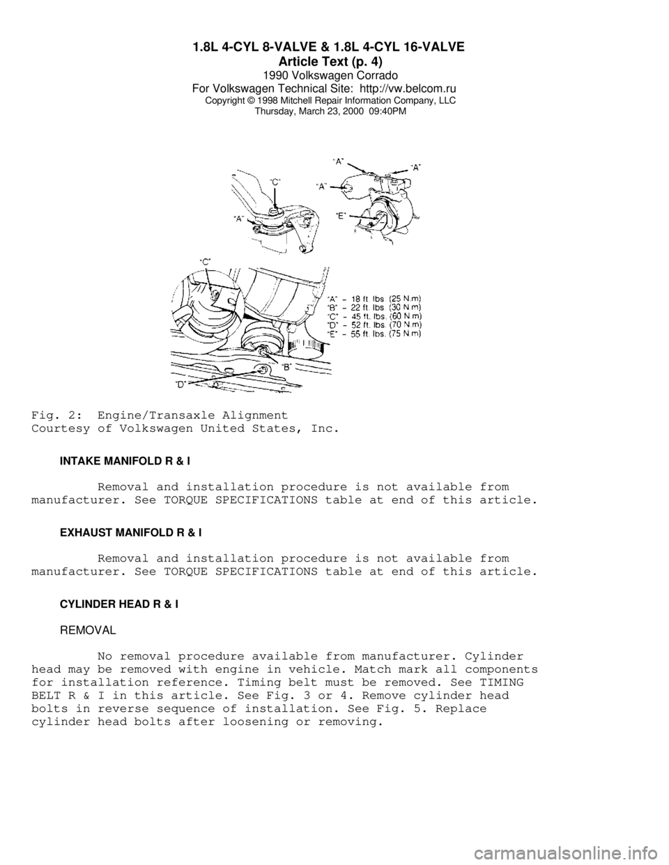
1) To install, reverse removal procedure. Engine alignment
adjustment is necessary whenever engine is removed or mounts are
loosened. To adjust, loosen through bolt on engine mount "A". Loosen
transmission transaxle mount "B" bolts. Loosen front engine mount and
bracket. See Fig. 2.
2) Lightly rock engine and transaxle to allow position to
Page 295 of 906
1.8L 4-CYL 8-VALVE & 1.8L 4-CYL 16-VALVE
Article Text (p. 4)
1990 Volkswagen Corrado
For Volkswagen Technical Site: http://vw.belcom.ru
Copyright © 1998 Mitchell Repair Information Company, LLC
Thursday, March 23, 2000 09:40PMFig. 2: Engine/Transaxle Alignment
Courtesy of Volkswagen United States, Inc.
INTAKE MANIFOLD R & I
Removal and installation procedure is not available from
manufacturer. See TORQUE SPECIFICATIONS table at end of this article.
EXHAUST MANIFOLD R & I
Removal and installation procedure is not available from
manufacturer. See TORQUE SPECIFICATIONS table at end of this article.
CYLINDER HEAD R & I
REMOVAL
No removal procedure available from manufacturer. Cylinder
head may be removed with engine in vehicle. Match mark all components
for installation reference. Timing belt must be removed. See TIMING
BELT R & I in this article. See Fig. 3 or 4. Remove cylinder head
bolts in reverse sequence of installation. See Fig. 5. Replace
cylinder head bolts after loosening or removing.
Page 298 of 906
1.8L 4-CYL 8-VALVE & 1.8L 4-CYL 16-VALVE
Article Text (p. 7)
1990 Volkswagen Corrado
For Volkswagen Technical Site: http://vw.belcom.ru
Copyright © 1998 Mitchell Repair Information Company, LLC
Thursday, March 23, 2000 09:40PM
INSTALLATION
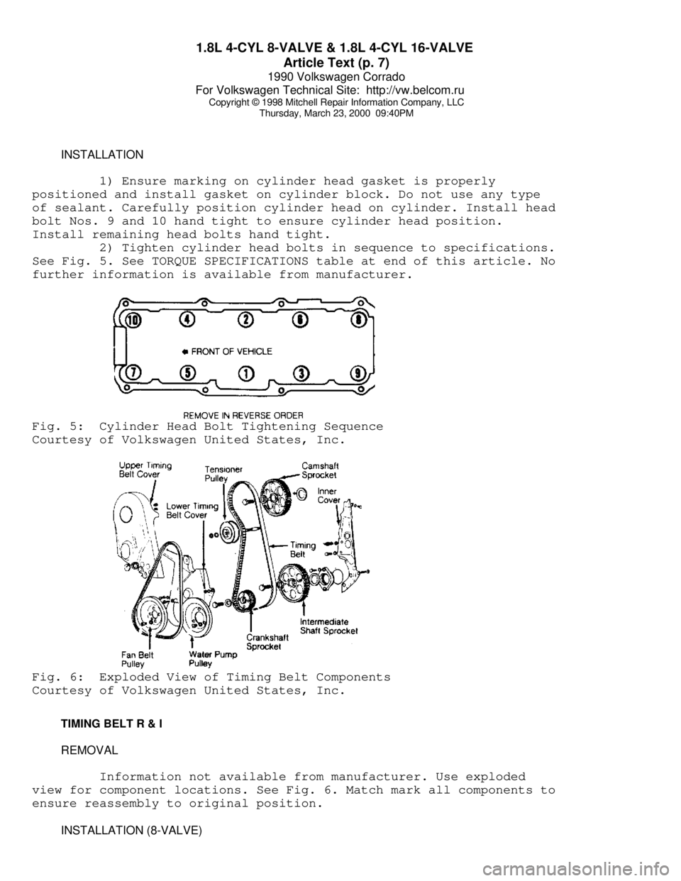
1) Ensure marking on cylinder head gasket is properly
positioned and install gasket on cylinder block. Do not use any type
of sealant. Carefully position cylinder head on cylinder. Install head
bolt Nos. 9 and 10 hand tight to ensure cylinder head position.
Install remaining head bolts hand tight.
2) Tighten cylinder head bolts in sequence to specifications.
See Fig. 5. See TORQUE SPECIFICATIONS table at end of this article. No
further information is available from manufacturer.Fig. 5: Cylinder Head Bolt Tightening Sequence
Courtesy of Volkswagen United States, Inc.Fig. 6: Exploded View of Timing Belt Components
Courtesy of Volkswagen United States, Inc.
TIMING BELT R & I
REMOVAL
Information not available from manufacturer. Use exploded
view for component locations. See Fig. 6. Match mark all components to
ensure reassembly to original position.
INSTALLATION (8-VALVE)
Page 299 of 906
1.8L 4-CYL 8-VALVE & 1.8L 4-CYL 16-VALVE
Article Text (p. 8)
1990 Volkswagen Corrado
For Volkswagen Technical Site: http://vw.belcom.ru
Copyright © 1998 Mitchell Repair Information Company, LLC
Thursday, March 23, 2000 09:40PM
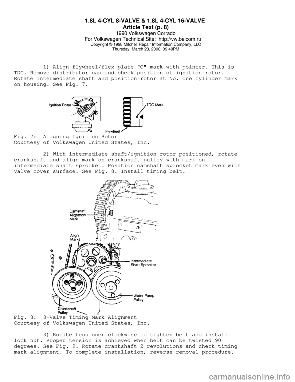
1) Align flywheel/flex plate "O" mark with pointer. This is
TDC. Remove distributor cap and check position of ignition rotor.
Rotate intermediate shaft and position rotor at No. one cylinder mark
on housing. See Fig. 7.Fig. 7: Aligning Ignition Rotor
Courtesy of Volkswagen United States, Inc.
2) With intermediate shaft/ignition rotor positioned, rotate
crankshaft and align mark on crankshaft pulley with mark on
intermediate shaft sprocket. Position camshaft sprocket mark even with
valve cover surface. See Fig. 8. Install timing belt.Fig. 8: 8-Valve Timing Mark Alignment
Courtesy of Volkswagen United States, Inc.
3) Rotate tensioner clockwise to tighten belt and install
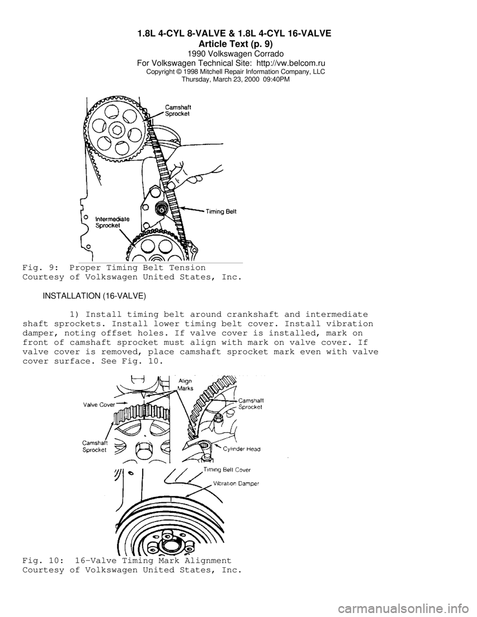
lock nut. Proper tension is achieved when belt can be twisted 90
degrees. See Fig. 9. Rotate crankshaft 2 revolutions and check timing
mark alignment. To complete installation, reverse removal procedure.
Page 300 of 906
1.8L 4-CYL 8-VALVE & 1.8L 4-CYL 16-VALVE
Article Text (p. 9)
1990 Volkswagen Corrado
For Volkswagen Technical Site: http://vw.belcom.ru
Copyright © 1998 Mitchell Repair Information Company, LLC
Thursday, March 23, 2000 09:40PMFig. 9: Proper Timing Belt Tension
Courtesy of Volkswagen United States, Inc.
INSTALLATION (16-VALVE)
1) Install timing belt around crankshaft and intermediate
shaft sprockets. Install lower timing belt cover. Install vibration
damper, noting offset holes. If valve cover is installed, mark on
front of camshaft sprocket must align with mark on valve cover. If
valve cover is removed, place camshaft sprocket mark even with valve
cover surface. See Fig. 10.Fig. 10: 16-Valve Timing Mark Alignment
Courtesy of Volkswagen United States, Inc.
Page 301 of 906
1.8L 4-CYL 8-VALVE & 1.8L 4-CYL 16-VALVE
Article Text (p. 10)
1990 Volkswagen Corrado
For Volkswagen Technical Site: http://vw.belcom.ru
Copyright © 1998 Mitchell Repair Information Company, LLC
Thursday, March 23, 2000 09:40PM
2) Align crankshaft sprocket mark with mark on lower timing
belt cover. See Fig. 10. Install timing belt around camshaft sprocket.
Rotate tensioner clockwise until Timing Belt Tension Scale (VW 210)
reads 13-14. Rotate crankshaft 2 revolutions and check timing mark
alignment. To complete installation, reverse removal procedure.
CAMSHAFT OIL SEAL R & I
REMOVAL
1) Remove upper timing belt cover. Place crankshaft at TDC
with No. one cylinder on compression stroke. Remove timing belt from
camshaft sprocket. Remove camshaft sprocket. Remove Woodruff key.
Install camshaft sprocket bolt and washer until washer is tight
against camshaft.
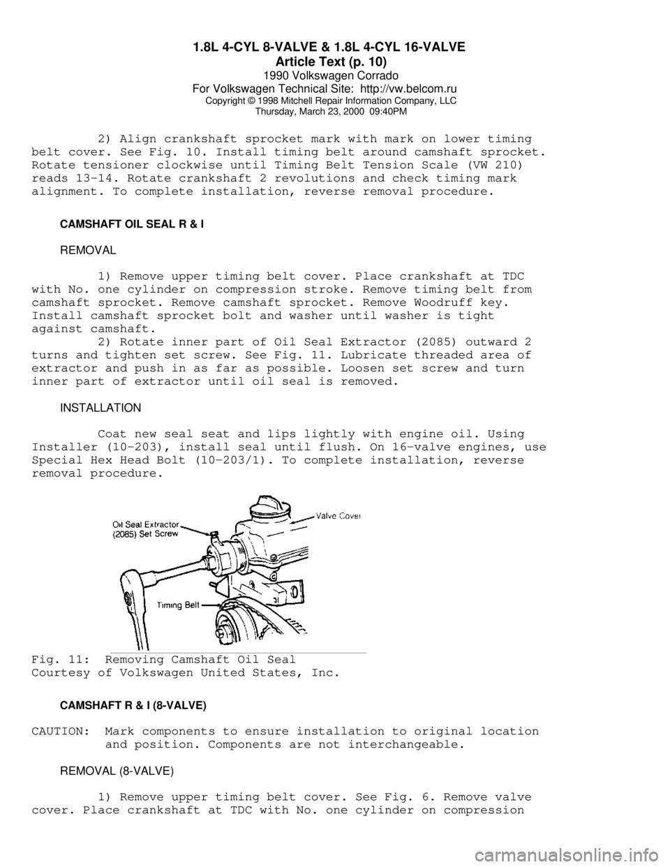
2) Rotate inner part of Oil Seal Extractor (2085) outward 2
turns and tighten set screw. See Fig. 11. Lubricate threaded area of
extractor and push in as far as possible. Loosen set screw and turn
inner part of extractor until oil seal is removed.
INSTALLATION
Coat new seal seat and lips lightly with engine oil. Using
Installer (10-203), install seal until flush. On 16-valve engines, use
Special Hex Head Bolt (10-203/1). To complete installation, reverse
removal procedure.Fig. 11: Removing Camshaft Oil Seal
Courtesy of Volkswagen United States, Inc.
CAMSHAFT R & I (8-VALVE)
CAUTION: Mark components to ensure installation to original location
and position. Components are not interchangeable.
REMOVAL (8-VALVE)
1) Remove upper timing belt cover. See Fig. 6. Remove valve
cover. Place crankshaft at TDC with No. one cylinder on compression