1990 VOLKSWAGEN CORRADO timing belt
[x] Cancel search: timing beltPage 302 of 906

1.8L 4-CYL 8-VALVE & 1.8L 4-CYL 16-VALVE
Article Text (p. 11)
1990 Volkswagen Corrado
For Volkswagen Technical Site: http://vw.belcom.ru
Copyright © 1998 Mitchell Repair Information Company, LLC
Thursday, March 23, 2000 09:40PM
stroke. Remove timing belt from camshaft sprocket. Remove camshaft
sprocket. Remove Woodruff key. Check camshaft end play with cam
followers removed and bearing cap Nos. 1 and 5 installed. See CAMSHAFT
table at end of this article.
2) Remove bearing cap Nos. 1, 3 and 5 evenly a little at a
time. Repeat for remaining caps. Lift camshaft out of cylinder head.
See INSPECTION below.
INSPECTION
1) Check camshaft bearing oil clearance. See ENGINE
SPECIFICATIONS at end of this article. If oil clearance is greater
than specifications, install new camshaft and recheck clearance.
2) If clearance is still greater than specifications,
replace cylinder head. If replacing camshaft(s), ensure identification
number between lobes of cylinder No. one, are the same.
INSTALLATION (8-VALVE)
1) On engines with oil spray jets, position spray at right
angle to camshaft. Place camshaft in cylinder head with both high
points of lobes, for No. one cylinder facing upward. Install bearing
cap Nos. 1, 3 and 5.
2) Tighten evenly a little at a time. Repeat procedure for
remaining bearing caps. To complete installation, reverse removal
procedure. Ensure timing marks are properly aligned. Allow lifters to
bleed down for 30 minutes before starting engine.
CAMSHAFT R & I (16-VALVE)
REMOVAL (16-VALVE)
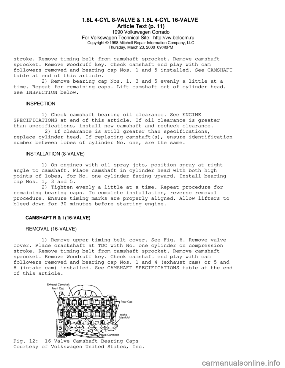
1) Remove upper timing belt cover. See Fig. 6. Remove valve
cover. Place crankshaft at TDC with No. one cylinder on compression
stroke. Remove timing belt from camshaft sprocket. Remove camshaft
sprocket. Remove Woodruff key. Check camshaft end play with cam
followers removed and bearing cap Nos. 1 and 4 (exhaust cam) or 5 and
8 (intake cam) installed. See CAMSHAFT SPECIFICATIONS table at the end
of this article.Fig. 12: 16-Valve Camshaft Bearing Caps
Courtesy of Volkswagen United States, Inc.
Page 309 of 906

1.8L 4-CYL 8-VALVE & 1.8L 4-CYL 16-VALVE
Article Text (p. 18)
1990 Volkswagen Corrado
For Volkswagen Technical Site: http://vw.belcom.ru
Copyright © 1998 Mitchell Repair Information Company, LLC
Thursday, March 23, 2000 09:40PM
Install new flywheel bolts.
FRONT COVER OIL SEAL R & I
REMOVAL
Remove timing belt. See REMOVAL under TIMING BELT R & I in
this article. Rotate inner part of Oil Seal Extractor (2085) outward 2
turns and tighten set screw. See Fig. 11. Lubricate threaded area of
extractor and push in as far as possible. Loosen set screw and turn
inner part of extractor until oil seal is removed.
INSTALLATION
Lubricate outer edge and lip of new seal. Place guide sleeve
from Seal Installer (3083) onto crankshaft. Push oil seal over guide
sleeve. Press seal completely into position. To complete installation,
reverse removal procedure.
INTERMEDIATE SHAFT ASSEMBLY
Remove timing belt. See REMOVAL under TIMING BELT in this
article. Mark distributor assembly for installation reference and
remove distributor assembly. Check intermediate shaft end play. See
INTERMEDIATE SHAFT END PLAY SPECIFICATION table following this
paragraph. Remove intermediate shaft sprocket. Remove intermediate
shaft seal flange. Replace seal (if necessary). To install, reverse
removal procedure. See ENGINE SPECIFICATIONS at end of this article.
INTERMEDIATE SHAFT END PLAY SPECIFICATIONÄÄÄÄÄÄÄÄÄÄÄÄÄÄÄÄÄÄÄÄÄÄÄÄÄÄÄÄÄÄÄÄÄÄÄÄÄÄÄÄÄÄÄÄÄApplication In. (mm)
1.8L ........................... .010 (.25)
ÄÄÄÄÄÄÄÄÄÄÄÄÄÄÄÄÄÄÄÄÄÄÄÄÄÄÄÄÄÄÄÄÄÄÄÄÄÄÄÄÄÄÄÄÄ CYLINDER BLOCK INSPECTION
DO NOT measure cylinder block while mounted on an engine
stand. Inaccurate measurements may be achieved. Check cylinder bore
for wear, out-of-round and taper. Pistons are available in oversize.
Cylinder block bore may be machined. Check cylinder block for warpage.
See ENGINE SPECIFICATIONS at end of this article.
ENGINE OILING SYSTEM SPECIFICATIONS
CRANKCASE CAPACITY
CRANKCASE CAPACITY TABLE
ÄÄÄÄÄÄÄÄÄÄÄÄÄÄÄÄÄÄÄÄÄÄÄÄÄÄÄÄÄÄÄÄÄÄÄÄÄÄÄÄÄÄÄÄÄÄÄÄÄÄÄÄÄÄÄ With Filter Without Filter
Page 312 of 906

1.8L 4-CYL 8-VALVE & 1.8L 4-CYL 16-VALVE
Article Text (p. 21)
1990 Volkswagen Corrado
For Volkswagen Technical Site: http://vw.belcom.ru
Copyright © 1998 Mitchell Repair Information Company, LLC
Thursday, March 23, 2000 09:40PM
Engine Mounts (4)
A Bolt/Nut ..................................... 18 (24)
B Bolt ......................................... 22 (30)
C Bolt ......................................... 44 (60)
D Bolt ......................................... 53 (72)
E Bolt ......................................... 59 (80)
Engine-to-Transaxle Bolt
M10 ............................................ 33 (45)
M12 ............................................ 55 (75)
Exhaust Manifold Nut ............................. 18 (24)
Flywheel-to-Crankshaft Bolt (5) ................. 74 (100)
Intake Manifold Bolt ............................. 18 (24)
Intermediate Shaft Sprocket Bolt
8-Valve ........................................ 59 (80)
16-Valve ....................................... 48 (65)
Main Bearing Cap Bolt (6) ........................ 48 (65)
Oil Pan Bolt ..................................... 15 (20)
Oil Pump
Short Bolt ...................................... 7 (10)
Long Bolt ...................................... 15 (20)
Power Steering Pump-to-Bracket Nut ............... 14 (19)
Timing Belt Tensioner Pulley Nut ................. 33 (45)
Water Pump Housing-to-Block ...................... 15 (20)
Water Pump Pulley ................................ 15 (20)
INCH Lbs. (N.m)
Piston Oil Spray
Nozzle Bolt .................................... 84 (10)
Thermostat Housing-to-Water
Pump Housing ................................... 84 (10)
Upper & Lower Timing Belt Cover Bolt .............. 53 (6)
Water Pump-to-Housing ............................ 84 (10)
(1) - Tighten an additional 180 degrees. Ensure a new bolt
is used.
(2) - Tighten in sequence. See Fig. 5.
(3) - Turn bolts 180 degrees further in one continuous
movement. Two separate 90 degree turns may be used.
(4) - See Fig. 2.
(5) - Apply sealant to threads and tighten evenly and
diagonally.
(6) - Tighten in several steps evenly.ÄÄÄÄÄÄÄÄÄÄÄÄÄÄÄÄÄÄÄÄÄÄÄÄÄÄÄÄÄÄÄÄÄÄÄÄÄÄÄÄÄÄÄÄÄÄÄÄÄÄÄÄÄÄÄÄÄÄÄÄ ENGINE SPECIFICATIONS
GENERAL ENGINE SPECIFICATIONS
GENERAL SPECIFICATIONS TABLE
ÄÄÄÄÄÄÄÄÄÄÄÄÄÄÄÄÄÄÄÄÄÄÄÄÄÄÄÄÄÄÄÄÄÄÄÄÄÄÄÄÄÄÄÄÄÄÄÄÄÄÄÄÄÄÄÄÄÄÄÄApplication Specifications
Page 374 of 906

AA - USING THIS SECTION (GENERAL HELP INFORMATION)
Article Text (p. 3)
1990 Volkswagen Corrado
For Volkswagen Technical Site: http://vw.belcom.ru
Copyright © 1998 Mitchell Repair Information Company, LLC
Thursday, March 23, 2000 09:41PM
* Replacement intervals.
* Belt adjustment.
* Engine Compression.
* Valve clearance.
* Valve Arrangement.
* Ignition coil specifications.
* High tension wire resistance.
* Spark plug type and gap.
* Firing order.
* Ignition timing.
* Fuel pump performance and injector resistance specifications
* Slow and fast idle speed and mixture specifications.
* Carbon monoxide (CO) level specifications.
* Throttle position sensor/switch specifications.
C - SPECIFICATIONS
This is a collection of quick-reference type specifications.
This article is helpful when you are familiar with proper adjustment
procedures and only need specifications. Included in this section are:
* Battery specifications.
* Fluid capacities.
* Replacement intervals.
* Belt adjustment.
* Engine Compression.
* Valve clearance.
* Valve Arrangement.
* Ignition coil specifications.
* High tension wire resistance.
* Spark plug type and gap.
* Firing order.
* Ignition timing.
* Fuel pump performance and injector resistance specifications
* Slow and fast idle speed and mixture specifications.
* Carbon monoxide (CO) level specifications.
* Throttle position sensor/switch specifications.
D - ADJUSTMENTS
This article contains the information that use to be included
in the TUNE-UP section. Checking and adjusting valves, spark plugs,
spark plug wires, base ignition timing and idle speed are found in
this section. Use this article for routine maintenance. Also, if you
have a driveability problem, ensure all on-vehicle adjustments are
correct before proceeding with any diagnosis.
E - THEORY/OPERATION
Page 433 of 906

C - SPECIFICATIONS
Article Text (p. 5)
1990 Volkswagen Corrado
For Volkswagen Technical Site: http://vw.belcom.ru
Copyright © 1998 Mitchell Repair Information Company, LLC
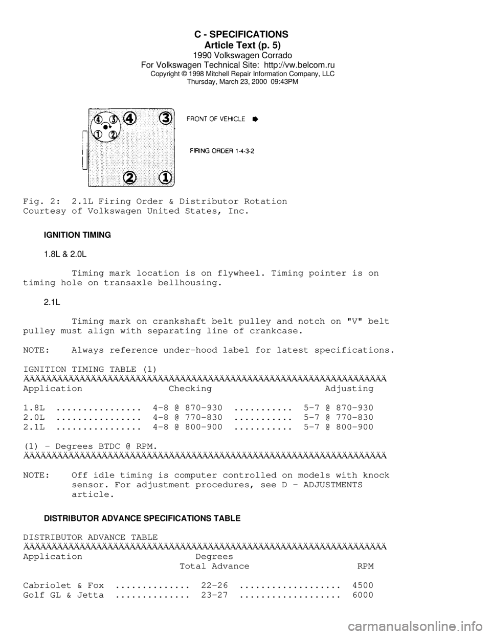
Thursday, March 23, 2000 09:43PMFig. 2: 2.1L Firing Order & Distributor Rotation
Courtesy of Volkswagen United States, Inc.
IGNITION TIMING
1.8L & 2.0L
Timing mark location is on flywheel. Timing pointer is on
timing hole on transaxle bellhousing.
2.1L
Timing mark on crankshaft belt pulley and notch on "V" belt
pulley must align with separating line of crankcase.
NOTE: Always reference under-hood label for latest specifications.
IGNITION TIMING TABLE (1)ÄÄÄÄÄÄÄÄÄÄÄÄÄÄÄÄÄÄÄÄÄÄÄÄÄÄÄÄÄÄÄÄÄÄÄÄÄÄÄÄÄÄÄÄÄÄÄÄÄÄÄÄÄÄÄÄÄÄÄÄÄÄÄÄÄApplication Checking Adjusting
1.8L ................ 4-8 @ 870-930 ........... 5-7 @ 870-930
2.0L ................ 4-8 @ 770-830 ........... 5-7 @ 770-830
2.1L ................ 4-8 @ 800-900 ........... 5-7 @ 800-900
(1) - Degrees BTDC @ RPM.
ÄÄÄÄÄÄÄÄÄÄÄÄÄÄÄÄÄÄÄÄÄÄÄÄÄÄÄÄÄÄÄÄÄÄÄÄÄÄÄÄÄÄÄÄÄÄÄÄÄÄÄÄÄÄÄÄÄÄÄÄÄÄÄÄÄNOTE: Off idle timing is computer controlled on models with knock
sensor. For adjustment procedures, see D - ADJUSTMENTS
article.
DISTRIBUTOR ADVANCE SPECIFICATIONS TABLE
DISTRIBUTOR ADVANCE TABLE
ÄÄÄÄÄÄÄÄÄÄÄÄÄÄÄÄÄÄÄÄÄÄÄÄÄÄÄÄÄÄÄÄÄÄÄÄÄÄÄÄÄÄÄÄÄÄÄÄÄÄÄÄÄÄÄÄÄÄÄÄÄÄÄÄÄApplication Degrees
Total Advance RPM
Cabriolet & Fox .............. 22-26 ................... 4500
Golf GL & Jetta .............. 23-27 ................... 6000
Page 439 of 906

D - ADJUSTMENTS
Article Text (p. 2)
1990 Volkswagen Corrado
For Volkswagen Technical Site: http://vw.belcom.ru
Copyright © 1998 Mitchell Repair Information Company, LLC
Thursday, March 23, 2000 09:43PM
connected, timing mark on flywheel should appear at pointer in hole.
NOTE: Before checking engine timing, raise engine speed above 2100
RPM at least 4 times. This must be done each time ignition
is turned off and restarted to clear ECU memory and by-pass
hot-start, fast-idle function.
3) If an adjustment is needed, turn ignition off and loosen
distributor hold-down bolt (2.0L has 2 hold-down bolts) just enough to
move distributor by hand. Start engine and allow to idle. Turn
distributor until timing mark is aligned with pointer in bellhousing.
4) Stop engine and tighten hold down bolt to 18 ft. lbs. (24
N.m). On 2.0L tighten hold-down bolts to 87 INCH lbs. (10 N.m). Check
and readjust if necessary and install plastic plug in inspection hole.
VANAGON
1) Engine oil temperature must be 176ø F (80ø C). Connect
timing light and tachometer. Start engine and allow to idle. Check
ignition timing at 800-1000 RPM.
NOTE: Before checking engine timing, raise engine speed above 2100
RPM at least 4 times. This must be done each time ignition
is turned off and restarted to clear ECU memory and by-pass
hot-start, fast-idle function.
2) If an adjustment is needed, turn ignition off and loosen
distributor hold-down bolt just enough to move distributor by hand.
Remove connectors from idle stabilizer by squeezing connectors then
pulling apart. Plug idle stabilizer connectors together.
3) Start and allow engine to idle. Turn distributor until
notch on V-belt pulley matches separation in case. Set timing and RPM.
Reconnect electrical connectors to idle stabilizer. Tighten
distributor clamp bolt.
IGNITION TIMING TABLE
IGNITION TIMING (Degrees BTDC @ RPM)
ÄÄÄÄÄÄÄÄÄÄÄÄÄÄÄÄÄÄÄÄÄÄÄÄÄÄÄÄÄÄÄÄÄÄÄÄÄÄÄÄÄÄÄÄÄÄÄÄÄÄÄÄÄÄÄÄÄÄÄÄÄÄÄÄÄÄÄÄÄÄApplication Checking Adjusting
1.8L ..................... 4-8 @ 870-930 ........... 5-7 @ 870-930
2.0L ..................... 4-8 @ 770-830 ........... 5-7 @ 770-830
2.1L ..................... 4-8 @ 800-900 ........... 5-7 @ 800-900
ÄÄÄÄÄÄÄÄÄÄÄÄÄÄÄÄÄÄÄÄÄÄÄÄÄÄÄÄÄÄÄÄÄÄÄÄÄÄÄÄÄÄÄÄÄÄÄÄÄÄÄÄÄÄÄÄÄÄÄÄÄÄÄÄÄÄÄÄÄÄ COLD (FAST) IDLE
Fast idle RPM is not adjustable.
IDLE SPEED & MIXTURE
Page 537 of 906

ENGINE OVERHAUL PROCEDURES - GENERAL INFORMATION
Article Text (p. 28)
1990 Volkswagen Corrado
For Volkswagen Technical Site: http://vw.belcom.ru
Copyright © 1998 Mitchell Repair Information Company, LLC
Thursday, March 23, 2000 09:44PM
Support camshaft at each end with "V" blocks. Position dial
indicator with tip resting on center bearing journal. Rotate camshaft
and note reading. If reading exceeds specification, replace camshaft.
Check cam lobe lift by measuring base circle of camshaft
using micrometer. Measure again at 90 degrees to tip of cam lobe. Cam
lift can be determined by subtracting base circle diameter from tip of
cam lobe measurement.
Different lift dimensions are given for intake and exhaust
cam lobes. Reading must be within specifications. Replace camshaft if
cam lobes or bearing journals are not within specifications.
Inspect camshaft gear for chipped, eroded or damaged teeth.
Replace gear if damaged. On camshafts using thrust plate, measure
distance between thrust plate and camshaft shoulder. Replace thrust
plate if not within specification.
CAMSHAFT BEARINGS
Removal & Installation
Remove the camshaft rear plug. The camshaft bearing remover
is assembled with its shoulder resting on the bearing to be removed
according to manufacturer's instructions. Tighten puller nut until
bearing is removed. Remove remaining bearings, leaving front and rear
bearings until last. These bearings act as guide for camshaft bearing
remover.
To install new bearings, puller is rearranged to pull
bearings toward the center of block. Ensure all lubrication passages
of bearing are aligned with cylinder block. Coat new camshaft rear
plug with sealant. Install camshaft rear plug. Ensure plug is even
in cylinder block.
CAMSHAFT INSTALLATION
Lubricate bearing surfaces and cam lobes with ample amount of
Molykote or camshaft lubricant. Carefully install camshaft. Use care
not to damage bearing journals during installation. Install thrust
plate retaining bolts (if equipped). Tighten bolts to specification.
On overhead camshafts, install bearing caps in original location.
Tighten bolts to specification. Check end play.
CAMSHAFT END PLAY
Using dial indicator, check end play. Position dial indicator
on front of engine block. Position indicator tip against camshaft.
Push camshaft toward rear of engine and adjust indicator to zero.
Move camshaft forward and note reading. Camshaft end play
must be within specification. End play may be adjusted by relocating
gear, shimming thrust plate or replacing thrust plate depending on
manufacturer.
TIMING CHAINS & BELTS
* PLEASE READ THIS FIRST *
Page 539 of 906

ENGINE OVERHAUL PROCEDURES - GENERAL INFORMATION
Article Text (p. 30)
1990 Volkswagen Corrado
For Volkswagen Technical Site: http://vw.belcom.ru
Copyright © 1998 Mitchell Repair Information Company, LLC
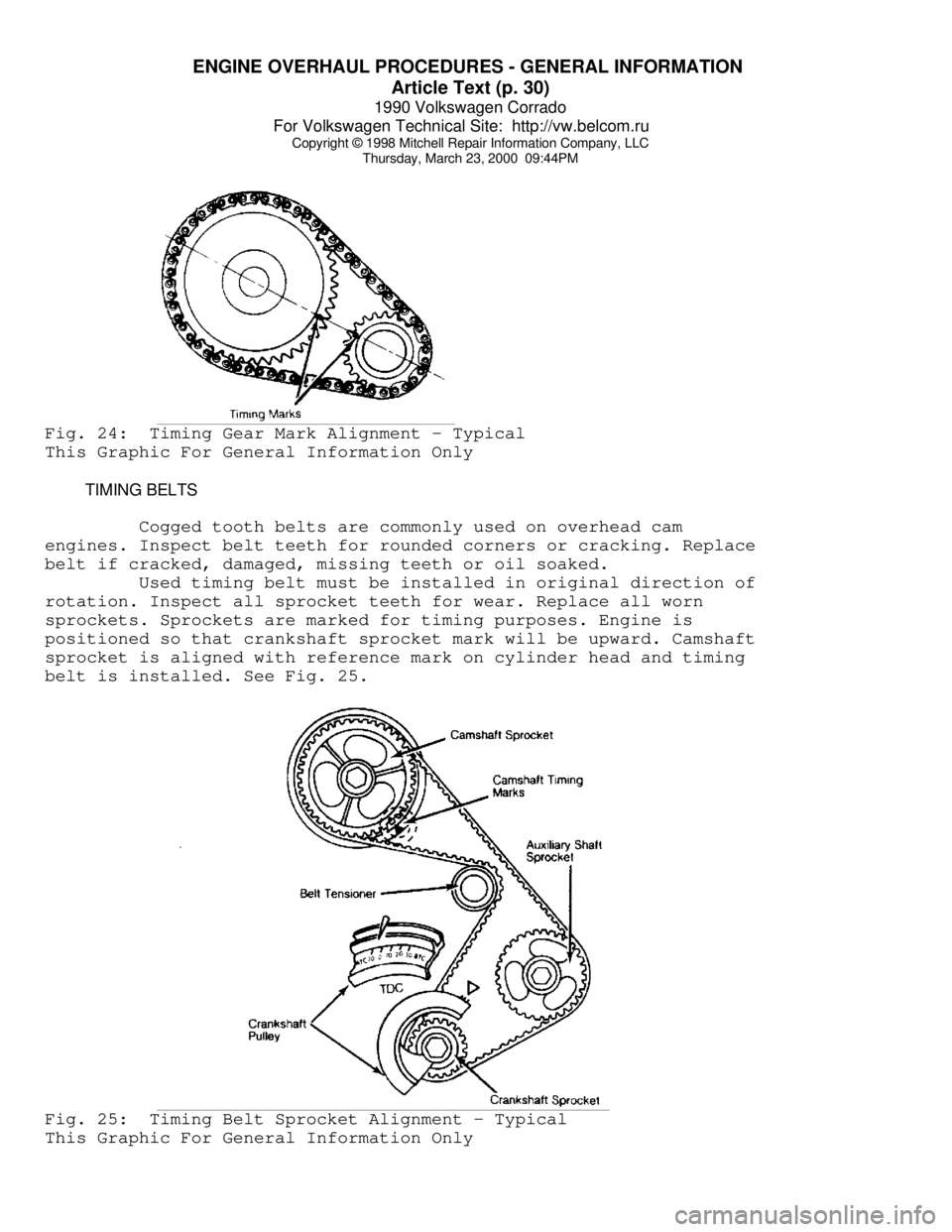
Thursday, March 23, 2000 09:44PMFig. 24: Timing Gear Mark Alignment - Typical
This Graphic For General Information Only
TIMING BELTS
Cogged tooth belts are commonly used on overhead cam
engines. Inspect belt teeth for rounded corners or cracking. Replace
belt if cracked, damaged, missing teeth or oil soaked.
Used timing belt must be installed in original direction of
rotation. Inspect all sprocket teeth for wear. Replace all worn
sprockets. Sprockets are marked for timing purposes. Engine is
positioned so that crankshaft sprocket mark will be upward. Camshaft
sprocket is aligned with reference mark on cylinder head and timing
belt is installed. See Fig. 25.Fig. 25: Timing Belt Sprocket Alignment - Typical
This Graphic For General Information Only