1990 VOLKSWAGEN CORRADO seat adjustment
[x] Cancel search: seat adjustmentPage 442 of 906

D - ADJUSTMENTS
Article Text (p. 5)
1990 Volkswagen Corrado
For Volkswagen Technical Site: http://vw.belcom.ru
Copyright © 1998 Mitchell Repair Information Company, LLC
Thursday, March 23, 2000 09:43PM
8) Connect adapter between connector and regulator. Connect
multimeter to adapter and turn switch to DCA 200 milliamp-range. Read
and compare current (4-16 milliamps) and CO values to specifications.
Turn engine off.
9) If CO reading is more than 1.2% at current reading of 4-16
milliamps, check for exhaust system leaks, ignition timing, injector
inserts for leaks, and fuel distributor for uneven fuel distribution.
If required, seal injector inserts with sealing compound and tighten
to 15 ft. lbs. (20 N.m).
10) If current reading is less than 4 milliamps or more than
16 milliamps, adjustment must be made with CO adjustment screw as
follows: remove boot from mixture control unit. Center punch hole in
CO adjusting hole and drill a 3/32" hole to a depth of 5/32" (4 mm).
DO NOT drill completely through as adjustment screw will be damaged.
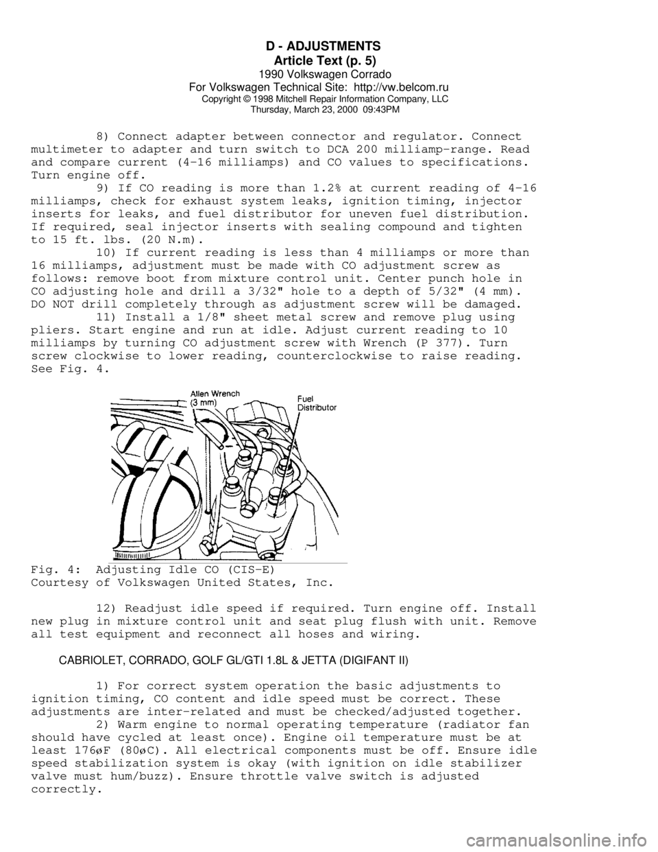
11) Install a 1/8" sheet metal screw and remove plug using
pliers. Start engine and run at idle. Adjust current reading to 10
milliamps by turning CO adjustment screw with Wrench (P 377). Turn
screw clockwise to lower reading, counterclockwise to raise reading.
See Fig. 4.Fig. 4: Adjusting Idle CO (CIS-E)
Courtesy of Volkswagen United States, Inc.
12) Readjust idle speed if required. Turn engine off. Install
new plug in mixture control unit and seat plug flush with unit. Remove
all test equipment and reconnect all hoses and wiring.
CABRIOLET, CORRADO, GOLF GL/GTI 1.8L & JETTA (DIGIFANT II)
1) For correct system operation the basic adjustments to
ignition timing, CO content and idle speed must be correct. These
adjustments are inter-related and must be checked/adjusted together.
2) Warm engine to normal operating temperature (radiator fan
should have cycled at least once). Engine oil temperature must be at
least 176øF (80øC). All electrical components must be off. Ensure idle
speed stabilization system is okay (with ignition on idle stabilizer
valve must hum/buzz). Ensure throttle valve switch is adjusted
correctly.
Page 514 of 906

ENGINE OVERHAUL PROCEDURES - GENERAL INFORMATION
Article Text (p. 5)
1990 Volkswagen Corrado
For Volkswagen Technical Site: http://vw.belcom.ru
Copyright © 1998 Mitchell Repair Information Company, LLC
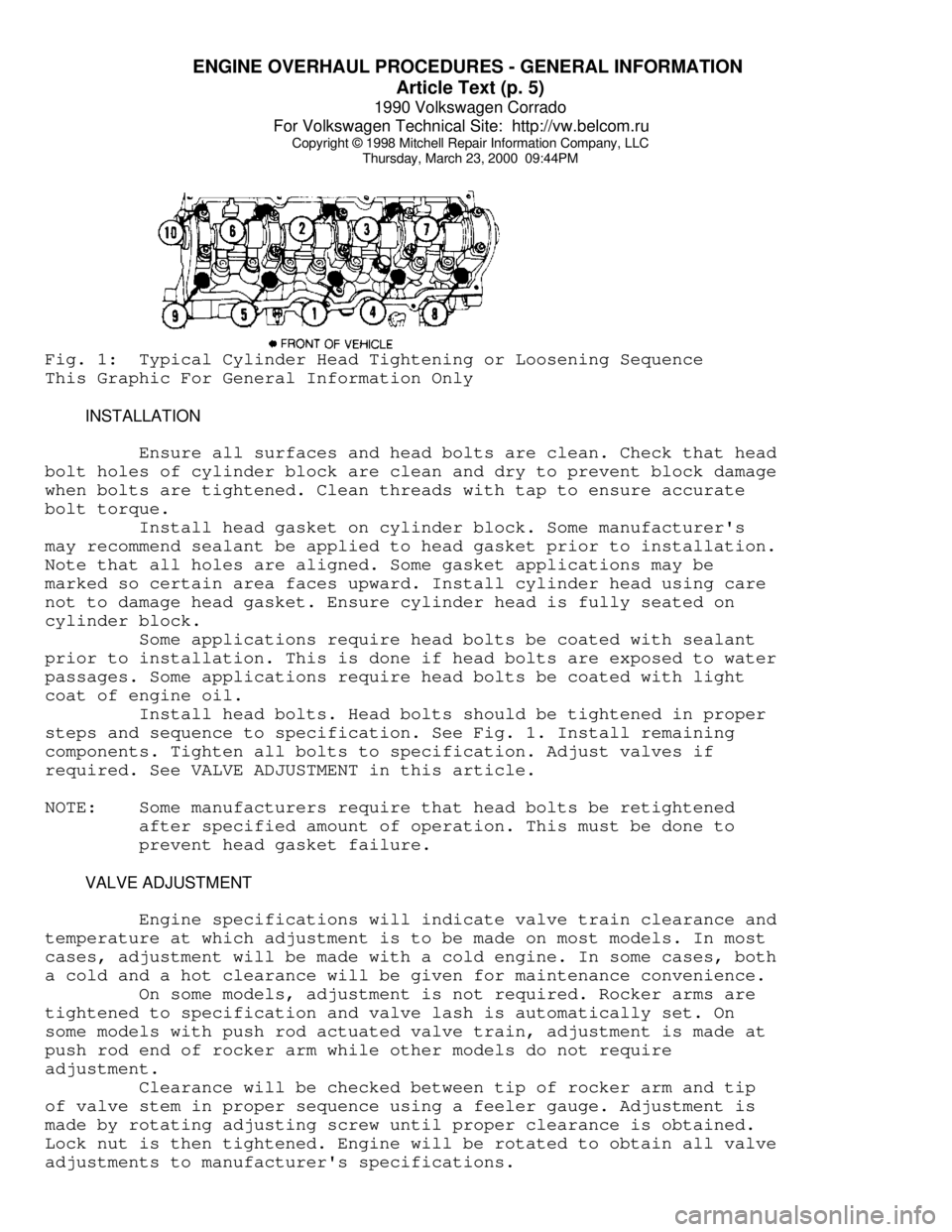
Thursday, March 23, 2000 09:44PMFig. 1: Typical Cylinder Head Tightening or Loosening Sequence
This Graphic For General Information Only
INSTALLATION
Ensure all surfaces and head bolts are clean. Check that head
bolt holes of cylinder block are clean and dry to prevent block damage
when bolts are tightened. Clean threads with tap to ensure accurate
bolt torque.
Install head gasket on cylinder block. Some manufacturer's
may recommend sealant be applied to head gasket prior to installation.
Note that all holes are aligned. Some gasket applications may be
marked so certain area faces upward. Install cylinder head using care
not to damage head gasket. Ensure cylinder head is fully seated on
cylinder block.
Some applications require head bolts be coated with sealant
prior to installation. This is done if head bolts are exposed to water
passages. Some applications require head bolts be coated with light
coat of engine oil.
Install head bolts. Head bolts should be tightened in proper
steps and sequence to specification. See Fig. 1. Install remaining
components. Tighten all bolts to specification. Adjust valves if
required. See VALVE ADJUSTMENT in this article.
NOTE: Some manufacturers require that head bolts be retightened
after specified amount of operation. This must be done to
prevent head gasket failure.
VALVE ADJUSTMENT
Engine specifications will indicate valve train clearance and
temperature at which adjustment is to be made on most models. In most
cases, adjustment will be made with a cold engine. In some cases, both
a cold and a hot clearance will be given for maintenance convenience.
On some models, adjustment is not required. Rocker arms are
tightened to specification and valve lash is automatically set. On
some models with push rod actuated valve train, adjustment is made at
push rod end of rocker arm while other models do not require
adjustment.
Clearance will be checked between tip of rocker arm and tip
of valve stem in proper sequence using a feeler gauge. Adjustment is
made by rotating adjusting screw until proper clearance is obtained.
Lock nut is then tightened. Engine will be rotated to obtain all valve
adjustments to manufacturer's specifications.
Page 515 of 906

ENGINE OVERHAUL PROCEDURES - GENERAL INFORMATION
Article Text (p. 6)
1990 Volkswagen Corrado
For Volkswagen Technical Site: http://vw.belcom.ru
Copyright © 1998 Mitchell Repair Information Company, LLC
Thursday, March 23, 2000 09:44PM
Some models require hydraulic lifter to be bled down and
clearance measured. Different length push rods can be used to obtain
proper clearance. Clearance will be checked between tip of rocker arm
and tip of valve stem in proper sequence using a feeler gauge.
On overhead cam engines designed without rocker arms actuate
valves directly on a cam follower. A hardened, removable disc is
installed between the cam lobe and lifter. Clearance will be checked
between cam heel and adjusting disc in proper sequence using a feeler
gauge. Engine will be rotated to obtain all valve adjustments.
On overhead cam engines designed with rocker arms, adjustment
is made at push rod end of rocker arm. Ensure that the valve to be
adjusted is riding on the heel of the cam on all engines. Clearance
will be checked between tip of rocker arm and tip of valve stem in
proper sequence using a feeler gauge. Adjustment is made by rotating
adjusting screw until proper clearance is obtained. Lock nut is then
tightened. Engine will be rotated to obtain all valve adjustments to
manufacturer's specifications.
CYLINDER HEAD OVERHAUL
* PLEASE READ THIS FIRST *
NOTE: Always refer to appropriate engine overhaul article in the
ENGINES section for complete overhaul procedures and
specifications for the vehicle being repaired.
DISASSEMBLY
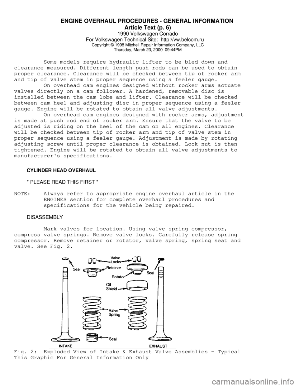
Mark valves for location. Using valve spring compressor,
compress valve springs. Remove valve locks. Carefully release spring
compressor. Remove retainer or rotator, valve spring, spring seat and
valve. See Fig. 2.Fig. 2: Exploded View of Intake & Exhaust Valve Assemblies - Typical
This Graphic For General Information Only
Page 523 of 906

ENGINE OVERHAUL PROCEDURES - GENERAL INFORMATION
Article Text (p. 14)
1990 Volkswagen Corrado
For Volkswagen Technical Site: http://vw.belcom.ru
Copyright © 1998 Mitchell Repair Information Company, LLC
Thursday, March 23, 2000 09:44PM
ROCKER ARMS & ASSEMBLIES
Rocker Studs
Rocker studs are either threaded or pressed in place.
Threaded studs are removed by locking 2 nuts on the stud. Unscrew the
stud by turning the jam nut. Coat the stud threads with Loctite and
install. Tighten to specification.
Pressed in stud can be removed using a stud puller. Ream the
stud bore to proper specification and press in a new oversize stud.
Pressed in studs are often replaced by cutting threads in the stud
bore to accept a threaded stud.
Rocker Arms & Shafts
Mark rocker arms for location. Remove rocker arm retaining
bolts. Remove rocker arms. Inspect rocker arms, shafts, bushings and
pivot balls (if equipped) for excessive wear. Inspect rocker arms
for wear in valve stem contact area. Measure rocker arm bushing I.D.
Replace bushings if excessively worn.
The rocker arm valve stem contact point can be reground,
using special fixture for valve grinding machine. Remove minimum
amount of material as possible. Ensure all oil passages are clear.
Install rocker arms in original locations. Ensure rocker arm is
properly seated in push rod. Tighten bolts to specification. Adjust
valves if required. See VALVE ADJUSTMENT in this article.
Pushrods
Remove rocker arms. Mark push rods for location. Remove push
rods. Push rods can be steel or aluminum, solid or hollow. Hollow
pushrods must be internally cleaned to ensure oil passage to the
rocker arms is cleaned. Check the pushrod for damage, such as loose
ends on steel tipped aluminum types.
Check push rod for straightness. Roll push rod on a flat
surface. Using feeler gauge, check clearance at center. Replace push
rod if bent. The push rod can also be supported at each end and
rotated. A dial indicator is used to detect bends in the push rod.
Lubricate ends of push rod and install push rod in original
location. Ensure push rod is properly seated in lifter. Install rocker
arm. Tighten bolts to specification. Adjust valves if required. See
VALVE ADJUSTMENT in this article.
LIFTERS
Hydraulic Lifters
Before replacing a hydraulic lifter for noisy operation,
ensure noise is not caused by worn rocker arms or valve tips.
Hydraulic lifter assemblies must be installed in original locations.
Remove the rocker arm assembly and push rod. Mark components for
location. Some applications require intake manifold, or lifter cover
removal. Remove lifter retainer plate (if used). To remove lifters,
use a hydraulic lifter remover or magnet. Different type lifters are
used. See Fig. 13.
Page 545 of 906

ENGINE OVERHAUL PROCEDURES - GENERAL INFORMATION
Article Text (p. 36)
1990 Volkswagen Corrado
For Volkswagen Technical Site: http://vw.belcom.ru
Copyright © 1998 Mitchell Repair Information Company, LLC
Thursday, March 23, 2000 09:44PM
to ensure correct amount of oil has filled crankcase. Check oil level
while pre-oiling.
If pressure oiler is not available, disconnect ignition
system. Remove oil pressure sending unit and replace with oil pressure
test gauge. Using starter motor, rotate engine starter until gauge
shows normal oil pressure for several seconds. DO NOT crank engine
for more than 30 seconds to avoid starter motor damage.
Ensure oil pressure has reached the most distant point from
the oil pump. Reinstall oil pressure sending unit. Reconnect ignition
system.
INITIAL START-UP
Start the engine and operate engine at low speed while
checking for coolant, fuel and oil leaks. Stop engine. Recheck coolant
and oil level. Adjust if necessary.
CAMSHAFT
Break-in procedure is required when a new or reground
camshaft has been installed. Operate and maintain engine speed between
1500-2500 RPM for approximately 30 minutes. Procedure may vary due to
manufacturers recommendations.
PISTON RINGS
Piston rings require a break-in procedure to ensure seating
of rings to cylinder walls. Serious damage may occur to rings if
correct procedures are not followed.
Extremely high piston ring temperatures are produced obtained
during break-in process. If rings are exposed to excessively high RPM
or high cylinder pressures, ring damage can occur. Follow piston ring
manufacturer's recommended break-in procedure.
FINAL ADJUSTMENTS
Check or adjust ignition timing and dwell (if applicable).
Adjust valves (if necessary). Adjust carburetion or injection idle
speed and mixture. Retighten cylinder heads (if required). If
cylinder head or block is aluminum, retighten bolts when engine is
cold. Follow the engine manufacturer's recommended break-in procedure
and maintenance schedule for new engines.
NOTE: Some manufacturer's require that head bolts be retightened
after specified amount of operation. This must be done to
prevent head gasket failure.
END OF ARTICLE
Page 696 of 906

SCHEDULED SERVICES
Article Text (p. 13)
1990 Volkswagen Corrado
For Volkswagen Technical Site: http://vw.belcom.ru
Copyright © 1998 Mitchell Repair Information Company, LLC
Thursday, March 23, 2000 09:49PM³ ³ Check Operation of Horn, Wipers/Washers & All Exterior Lights ³
ÃÄÄÄÅÄÄÄÄÄÄÄÄÄÄÄÄÄÄÄÄÄÄÄÄÄÄÄÄÄÄÄÄÄÄÄÄÄÄÄÄÄÄÄÄÄÄÄÄÄÄÄÄÄÄÄÄÄÄÄÄÄÄÄÄÄÄÄÄ´
³
³ Inspect Condition of Wiper Blades ³
ÃÄÄÄÅÄÄÄÄÄÄÄÄÄÄÄÄÄÄÄÄÄÄÄÄÄÄÄÄÄÄÄÄÄÄÄÄÄÄÄÄÄÄÄÄÄÄÄÄÄÄÄÄÄÄÄÄÄÄÄÄÄÄÄÄÄÄÄÄ´
³
³ Check Headlight Alignment ³
ÃÄÄÄÅÄÄÄÄÄÄÄÄÄÄÄÄÄÄÄÄÄÄÄÄÄÄÄÄÄÄÄÄÄÄÄÄÄÄÄÄÄÄÄÄÄÄÄÄÄÄÄÄÄÄÄÄÄÄÄÄÄÄÄÄÄÄÄÄ´
³
³ Lubricate Weatherstripping with Silicone ³
ÃÄÄÄÅÄÄÄÄÄÄÄÄÄÄÄÄÄÄÄÄÄÄÄÄÄÄÄÄÄÄÄÄÄÄÄÄÄÄÄÄÄÄÄÄÄÄÄÄÄÄÄÄÄÄÄÄÄÄÄÄÄÄÄÄÄÄÄÄ´
³
³ Door/Hood/Trunk Stops, Hinges & Locks ³
ÃÄÄÄÅÄÄÄÄÄÄÄÄÄÄÄÄÄÄÄÄÄÄÄÄÄÄÄÄÄÄÄÄÄÄÄÄÄÄÄÄÄÄÄÄÄÄÄÄÄÄÄÄÄÄÄÄÄÄÄÄÄÄÄÄÄÄÄÄ´
³
³ Check Body Drain Holes ³
ÃÄÄÄÅÄÄÄÄÄÄÄÄÄÄÄÄÄÄÄÄÄÄÄÄÄÄÄÄÄÄÄÄÄÄÄÄÄÄÄÄÄÄÄÄÄÄÄÄÄÄÄÄÄÄÄÄÄÄÄÄÄÄÄÄÄÄÄÄ´
³
³ Check Automatic Seat Belt Operation (1990-94) ³
ÃÄÄÄÅÄÄÄÄÄÄÄÄÄÄÄÄÄÄÄÄÄÄÄÄÄÄÄÄÄÄÄÄÄÄÄÄÄÄÄÄÄÄÄÄÄÄÄÄÄÄÄÄÄÄÄÄÄÄÄÄÄÄÄÄÄÄÄÄ´
³
³ Check Seat Belt Webbing and Release Mechanisms ³
ÃÄÄÄÅÄÄÄÄÄÄÄÄÄÄÄÄÄÄÄÄÄÄÄÄÄÄÄÄÄÄÄÄÄÄÄÄÄÄÄÄÄÄÄÄÄÄÄÄÄÄÄÄÄÄÄÄÄÄÄÄÄÄÄÄÄÄÄÄ´
³
³ Windshield Washer System ³
ÃÄÄÄÅÄÄÄÄÄÄÄÄÄÄÄÄÄÄÄÄÄÄÄÄÄÄÄÄÄÄÄÄÄÄÄÄÄÄÄÄÄÄÄÄÄÄÄÄÄÄÄÄÄÄÄÄÄÄÄÄÄÄÄÄÄÄÄÄ´
³
³ Parking Brake Adjustment ³
ÃÄÄÄÅÄÄÄÄÄÄÄÄÄÄÄÄÄÄÄÄÄÄÄÄÄÄÄÄÄÄÄÄÄÄÄÄÄÄÄÄÄÄÄÄÄÄÄÄÄÄÄÄÄÄÄÄÄÄÄÄÄÄÄÄÄÄÄÄ´
³
³ Check Clutch Adjustment ³
ÃÄÄÄÅÄÄÄÄÄÄÄÄÄÄÄÄÄÄÄÄÄÄÄÄÄÄÄÄÄÄÄÄÄÄÄÄÄÄÄÄÄÄÄÄÄÄÄÄÄÄÄÄÄÄÄÄÄÄÄÄÄÄÄÄÄÄÄÄ´
³
³ Suspension & Wheel Bearings ³
ÃÄÄÄÅÄÄÄÄÄÄÄÄÄÄÄÄÄÄÄÄÄÄÄÄÄÄÄÄÄÄÄÄÄÄÄÄÄÄÄÄÄÄÄÄÄÄÄÄÄÄÄÄÄÄÄÄÄÄÄÄÄÄÄÄÄÄÄÄ´
³
³ Check Shift Interlock Operation ³
ÃÄÄÄÅÄÄÄÄÄÄÄÄÄÄÄÄÄÄÄÄÄÄÄÄÄÄÄÄÄÄÄÄÄÄÄÄÄÄÄÄÄÄÄÄÄÄÄÄÄÄÄÄÄÄÄÄÄÄÄÄÄÄÄÄÄÄÄÄ´
³
³ Inspect Steering Linkage/Front Suspension ³
ÃÄÄÄÅÄÄÄÄÄÄÄÄÄÄÄÄÄÄÄÄÄÄÄÄÄÄÄÄÄÄÄÄÄÄÄÄÄÄÄÄÄÄÄÄÄÄÄÄÄÄÄÄÄÄÄÄÄÄÄÄÄÄÄÄÄÄÄÄ´
³
³ Lubricate Chassis ³
ÃÄÄÄÅÄÄÄÄÄÄÄÄÄÄÄÄÄÄÄÄÄÄÄÄÄÄÄÄÄÄÄÄÄÄÄÄÄÄÄÄÄÄÄÄÄÄÄÄÄÄÄÄÄÄÄÄÄÄÄÄÄÄÄÄÄÄÄÄ´
³
³ Inspect Brake Pads, Rotors and Calipers ³
ÃÄÄÄÅÄÄÄÄÄÄÄÄÄÄÄÄÄÄÄÄÄÄÄÄÄÄÄÄÄÄÄÄÄÄÄÄÄÄÄÄÄÄÄÄÄÄÄÄÄÄÄÄÄÄÄÄÄÄÄÄÄÄÄÄÄÄÄÄ´
³
³ Inspect Brake System Hoses & Lines ³
ÃÄÄÄÅÄÄÄÄÄÄÄÄÄÄÄÄÄÄÄÄÄÄÄÄÄÄÄÄÄÄÄÄÄÄÄÄÄÄÄÄÄÄÄÄÄÄÄÄÄÄÄÄÄÄÄÄÄÄÄÄÄÄÄÄÄÄÄÄ´
³
³ Inspect Shocks/Struts for Leakage ³
ÃÄÄÄÅÄÄÄÄÄÄÄÄÄÄÄÄÄÄÄÄÄÄÄÄÄÄÄÄÄÄÄÄÄÄÄÄÄÄÄÄÄÄÄÄÄÄÄÄÄÄÄÄÄÄÄÄÄÄÄÄÄÄÄÄÄÄÄÄ´
³
³ Inspect Tire Wear and Condition ³
ÃÄÄÄÅÄÄÄÄÄÄÄÄÄÄÄÄÄÄÄÄÄÄÄÄÄÄÄÄÄÄÄÄÄÄÄÄÄÄÄÄÄÄÄÄÄÄÄÄÄÄÄÄÄÄÄÄÄÄÄÄÄÄÄÄÄÄÄÄ´
³
³ Rotate Tires and Adjust Air Pressure (Including Spare) ³
ÃÄÄÄÅÄÄÄÄÄÄÄÄÄÄÄÄÄÄÄÄÄÄÄÄÄÄÄÄÄÄÄÄÄÄÄÄÄÄÄÄÄÄÄÄÄÄÄÄÄÄÄÄÄÄÄÄÄÄÄÄÄÄÄÄÄÄÄÄ´
³
³ Road Test ³
ÃÄÄÄÁÄÄÄÄÄÄÄÄÄÄÄÄÄÄÄÄÄÄÄÄÄÄÄÄÄÄÄÄÄÄÄÄÄÄÄÄÄÄÄÄÄÄÄÄÄÄÄÄÄÄÄÄÄÄÄÄÄÄÄÄÄÄÄÄ´
³ Replace
³
ÃÄÄÄÂÄÄÄÄÄÄÄÄÄÄÄÄÄÄÄÄÄÄÄÄÄÄÄÄÄÄÄÄÄÄÄÄÄÄÄÄÄÄÄÄÄÄÄÄÄÄÄÄÄÄÄÄÄÄÄÄÄÄÄÄÄÄÄÄ´
³
³ Engine Oil ³
ÃÄÄÄÅÄÄÄÄÄÄÄÄÄÄÄÄÄÄÄÄÄÄÄÄÄÄÄÄÄÄÄÄÄÄÄÄÄÄÄÄÄÄÄÄÄÄÄÄÄÄÄÄÄÄÄÄÄÄÄÄÄÄÄÄÄÄÄÄ´
³
³ Oil Filter ³
ÃÄÄÄÁÄÄÄÄÄÄÄÄÄÄÄÄÄÄÄÄÄÄÄÄÄÄÄÄÄÄÄÄÄÄÄÄÄÄÄÄÄÄÄÄÄÄÄÄÄÄÄÄÄÄÄÄÄÄÄÄÄÄÄÄÄÄÄÄ´
³ Lubrication Specifications
³
ÃÄÄÄÄÄÄÄÄÄÄÄÄÄÄÄÄÄÄÄÄÄÄÄÄÄÄÄÄÄÄÄÄÄÄÄÄÄÄÄÄÄÄÄÄÄÄÄÄÄÄÄÄÄÄÄÄÄÄÄÄÄÄÄÄÄÄÄÄ´
³ Application Specification
³
³
³
Page 699 of 906

SCHEDULED SERVICES
Article Text (p. 16)
1990 Volkswagen Corrado
For Volkswagen Technical Site: http://vw.belcom.ru
Copyright © 1998 Mitchell Repair Information Company, LLC
Thursday, March 23, 2000 09:50PM³ ³ Check Coolant Strength ³
ÃÄÄÄÅÄÄÄÄÄÄÄÄÄÄÄÄÄÄÄÄÄÄÄÄÄÄÄÄÄÄÄÄÄÄÄÄÄÄÄÄÄÄÄÄÄÄÄÄÄÄÄÄÄÄÄÄÄÄÄÄÄÄÄÄÄÄÄÄ´
³
³ Inspect For Fluid Leaks ³
ÃÄÄÄÅÄÄÄÄÄÄÄÄÄÄÄÄÄÄÄÄÄÄÄÄÄÄÄÄÄÄÄÄÄÄÄÄÄÄÄÄÄÄÄÄÄÄÄÄÄÄÄÄÄÄÄÄÄÄÄÄÄÄÄÄÄÄÄÄ´
³
³ Inspect/Adjust Accessory Drive Belts (Replace if Required) ³
ÃÄÄÄÅÄÄÄÄÄÄÄÄÄÄÄÄÄÄÄÄÄÄÄÄÄÄÄÄÄÄÄÄÄÄÄÄÄÄÄÄÄÄÄÄÄÄÄÄÄÄÄÄÄÄÄÄÄÄÄÄÄÄÄÄÄÄÄÄ´
³
³ Inspect/Adjust Camshaft Timing Belt (2.0L) ³
ÃÄÄÄÅÄÄÄÄÄÄÄÄÄÄÄÄÄÄÄÄÄÄÄÄÄÄÄÄÄÄÄÄÄÄÄÄÄÄÄÄÄÄÄÄÄÄÄÄÄÄÄÄÄÄÄÄÄÄÄÄÄÄÄÄÄÄÄÄ´
³
³ A/C Cooling & Heating System ³
ÃÄÄÄÅÄÄÄÄÄÄÄÄÄÄÄÄÄÄÄÄÄÄÄÄÄÄÄÄÄÄÄÄÄÄÄÄÄÄÄÄÄÄÄÄÄÄÄÄÄÄÄÄÄÄÄÄÄÄÄÄÄÄÄÄÄÄÄÄ´
³
³ Crankcase Ventilation System ³
ÃÄÄÄÅÄÄÄÄÄÄÄÄÄÄÄÄÄÄÄÄÄÄÄÄÄÄÄÄÄÄÄÄÄÄÄÄÄÄÄÄÄÄÄÄÄÄÄÄÄÄÄÄÄÄÄÄÄÄÄÄÄÄÄÄÄÄÄÄ´
³
³ Intake Air System ³
ÃÄÄÄÅÄÄÄÄÄÄÄÄÄÄÄÄÄÄÄÄÄÄÄÄÄÄÄÄÄÄÄÄÄÄÄÄÄÄÄÄÄÄÄÄÄÄÄÄÄÄÄÄÄÄÄÄÄÄÄÄÄÄÄÄÄÄÄÄ´
³
³ Idle Speed ³
ÃÄÄÄÅÄÄÄÄÄÄÄÄÄÄÄÄÄÄÄÄÄÄÄÄÄÄÄÄÄÄÄÄÄÄÄÄÄÄÄÄÄÄÄÄÄÄÄÄÄÄÄÄÄÄÄÄÄÄÄÄÄÄÄÄÄÄÄÄ´
³
³ Inspect Brake System ³
ÃÄÄÄÅÄÄÄÄÄÄÄÄÄÄÄÄÄÄÄÄÄÄÄÄÄÄÄÄÄÄÄÄÄÄÄÄÄÄÄÄÄÄÄÄÄÄÄÄÄÄÄÄÄÄÄÄÄÄÄÄÄÄÄÄÄÄÄÄ´
³
³ Check Exhaust System & Heat Shielding ³
ÃÄÄÄÅÄÄÄÄÄÄÄÄÄÄÄÄÄÄÄÄÄÄÄÄÄÄÄÄÄÄÄÄÄÄÄÄÄÄÄÄÄÄÄÄÄÄÄÄÄÄÄÄÄÄÄÄÄÄÄÄÄÄÄÄÄÄÄÄ´
³
³ Clean Battery and Battery Terminals ³
ÃÄÄÄÅÄÄÄÄÄÄÄÄÄÄÄÄÄÄÄÄÄÄÄÄÄÄÄÄÄÄÄÄÄÄÄÄÄÄÄÄÄÄÄÄÄÄÄÄÄÄÄÄÄÄÄÄÄÄÄÄÄÄÄÄÄÄÄÄ´
³
³ Inspect Fuel/Tank/Cap/Lines ³
ÃÄÄÄÅÄÄÄÄÄÄÄÄÄÄÄÄÄÄÄÄÄÄÄÄÄÄÄÄÄÄÄÄÄÄÄÄÄÄÄÄÄÄÄÄÄÄÄÄÄÄÄÄÄÄÄÄÄÄÄÄÄÄÄÄÄÄÄÄ´
³
³ Check Operation of Horn, Wipers/Washers & All Exterior Lights ³
ÃÄÄÄÅÄÄÄÄÄÄÄÄÄÄÄÄÄÄÄÄÄÄÄÄÄÄÄÄÄÄÄÄÄÄÄÄÄÄÄÄÄÄÄÄÄÄÄÄÄÄÄÄÄÄÄÄÄÄÄÄÄÄÄÄÄÄÄÄ´
³
³ Inspect Condition of Wiper Blades ³
ÃÄÄÄÅÄÄÄÄÄÄÄÄÄÄÄÄÄÄÄÄÄÄÄÄÄÄÄÄÄÄÄÄÄÄÄÄÄÄÄÄÄÄÄÄÄÄÄÄÄÄÄÄÄÄÄÄÄÄÄÄÄÄÄÄÄÄÄÄ´
³
³ Check Headlight Alignment ³
ÃÄÄÄÅÄÄÄÄÄÄÄÄÄÄÄÄÄÄÄÄÄÄÄÄÄÄÄÄÄÄÄÄÄÄÄÄÄÄÄÄÄÄÄÄÄÄÄÄÄÄÄÄÄÄÄÄÄÄÄÄÄÄÄÄÄÄÄÄ´
³
³ Lubricate Weatherstripping with Silicone ³
ÃÄÄÄÅÄÄÄÄÄÄÄÄÄÄÄÄÄÄÄÄÄÄÄÄÄÄÄÄÄÄÄÄÄÄÄÄÄÄÄÄÄÄÄÄÄÄÄÄÄÄÄÄÄÄÄÄÄÄÄÄÄÄÄÄÄÄÄÄ´
³
³ Door/Hood/Trunk Stops, Hinges & Locks ³
ÃÄÄÄÅÄÄÄÄÄÄÄÄÄÄÄÄÄÄÄÄÄÄÄÄÄÄÄÄÄÄÄÄÄÄÄÄÄÄÄÄÄÄÄÄÄÄÄÄÄÄÄÄÄÄÄÄÄÄÄÄÄÄÄÄÄÄÄÄ´
³
³ Check Body Drain Holes ³
ÃÄÄÄÅÄÄÄÄÄÄÄÄÄÄÄÄÄÄÄÄÄÄÄÄÄÄÄÄÄÄÄÄÄÄÄÄÄÄÄÄÄÄÄÄÄÄÄÄÄÄÄÄÄÄÄÄÄÄÄÄÄÄÄÄÄÄÄÄ´
³
³ Check Automatic Seat Belt Operation (1990-94) ³
ÃÄÄÄÅÄÄÄÄÄÄÄÄÄÄÄÄÄÄÄÄÄÄÄÄÄÄÄÄÄÄÄÄÄÄÄÄÄÄÄÄÄÄÄÄÄÄÄÄÄÄÄÄÄÄÄÄÄÄÄÄÄÄÄÄÄÄÄÄ´
³
³ Check Seat Belt Webbing and Release Mechanisms ³
ÃÄÄÄÅÄÄÄÄÄÄÄÄÄÄÄÄÄÄÄÄÄÄÄÄÄÄÄÄÄÄÄÄÄÄÄÄÄÄÄÄÄÄÄÄÄÄÄÄÄÄÄÄÄÄÄÄÄÄÄÄÄÄÄÄÄÄÄÄ´
³
³ Windshield Washer System ³
ÃÄÄÄÅÄÄÄÄÄÄÄÄÄÄÄÄÄÄÄÄÄÄÄÄÄÄÄÄÄÄÄÄÄÄÄÄÄÄÄÄÄÄÄÄÄÄÄÄÄÄÄÄÄÄÄÄÄÄÄÄÄÄÄÄÄÄÄÄ´
³
³ Parking Brake Adjustment ³
ÃÄÄÄÅÄÄÄÄÄÄÄÄÄÄÄÄÄÄÄÄÄÄÄÄÄÄÄÄÄÄÄÄÄÄÄÄÄÄÄÄÄÄÄÄÄÄÄÄÄÄÄÄÄÄÄÄÄÄÄÄÄÄÄÄÄÄÄÄ´
³
³ Check Clutch Adjustment ³
ÃÄÄÄÅÄÄÄÄÄÄÄÄÄÄÄÄÄÄÄÄÄÄÄÄÄÄÄÄÄÄÄÄÄÄÄÄÄÄÄÄÄÄÄÄÄÄÄÄÄÄÄÄÄÄÄÄÄÄÄÄÄÄÄÄÄÄÄÄ´
³
³ Suspension & Wheel Bearings ³
ÃÄÄÄÅÄÄÄÄÄÄÄÄÄÄÄÄÄÄÄÄÄÄÄÄÄÄÄÄÄÄÄÄÄÄÄÄÄÄÄÄÄÄÄÄÄÄÄÄÄÄÄÄÄÄÄÄÄÄÄÄÄÄÄÄÄÄÄÄ´
³
³ Check Shift Interlock Operation ³
ÃÄÄÄÅÄÄÄÄÄÄÄÄÄÄÄÄÄÄÄÄÄÄÄÄÄÄÄÄÄÄÄÄÄÄÄÄÄÄÄÄÄÄÄÄÄÄÄÄÄÄÄÄÄÄÄÄÄÄÄÄÄÄÄÄÄÄÄÄ´
³
³ Inspect Steering Linkage/Front Suspension ³
ÃÄÄÄÅÄÄÄÄÄÄÄÄÄÄÄÄÄÄÄÄÄÄÄÄÄÄÄÄÄÄÄÄÄÄÄÄÄÄÄÄÄÄÄÄÄÄÄÄÄÄÄÄÄÄÄÄÄÄÄÄÄÄÄÄÄÄÄÄ´
Page 703 of 906

SCHEDULED SERVICES
Article Text (p. 20)
1990 Volkswagen Corrado
For Volkswagen Technical Site: http://vw.belcom.ru
Copyright © 1998 Mitchell Repair Information Company, LLC
Thursday, March 23, 2000 09:50PM³ ³ Check Exhaust System & Heat Shielding ³
ÃÄÄÄÅÄÄÄÄÄÄÄÄÄÄÄÄÄÄÄÄÄÄÄÄÄÄÄÄÄÄÄÄÄÄÄÄÄÄÄÄÄÄÄÄÄÄÄÄÄÄÄÄÄÄÄÄÄÄÄÄÄÄÄÄÄÄÄÄ´
³
³ Clean Battery and Battery Terminals ³
ÃÄÄÄÅÄÄÄÄÄÄÄÄÄÄÄÄÄÄÄÄÄÄÄÄÄÄÄÄÄÄÄÄÄÄÄÄÄÄÄÄÄÄÄÄÄÄÄÄÄÄÄÄÄÄÄÄÄÄÄÄÄÄÄÄÄÄÄÄ´
³
³ Inspect Fuel/Tank/Cap/Lines ³
ÃÄÄÄÅÄÄÄÄÄÄÄÄÄÄÄÄÄÄÄÄÄÄÄÄÄÄÄÄÄÄÄÄÄÄÄÄÄÄÄÄÄÄÄÄÄÄÄÄÄÄÄÄÄÄÄÄÄÄÄÄÄÄÄÄÄÄÄÄ´
³
³ Check Operation of Horn, Wipers/Washers & All Exterior Lights ³
ÃÄÄÄÅÄÄÄÄÄÄÄÄÄÄÄÄÄÄÄÄÄÄÄÄÄÄÄÄÄÄÄÄÄÄÄÄÄÄÄÄÄÄÄÄÄÄÄÄÄÄÄÄÄÄÄÄÄÄÄÄÄÄÄÄÄÄÄÄ´
³
³ Inspect Condition of Wiper Blades ³
ÃÄÄÄÅÄÄÄÄÄÄÄÄÄÄÄÄÄÄÄÄÄÄÄÄÄÄÄÄÄÄÄÄÄÄÄÄÄÄÄÄÄÄÄÄÄÄÄÄÄÄÄÄÄÄÄÄÄÄÄÄÄÄÄÄÄÄÄÄ´
³
³ Check Headlight Alignment ³
ÃÄÄÄÅÄÄÄÄÄÄÄÄÄÄÄÄÄÄÄÄÄÄÄÄÄÄÄÄÄÄÄÄÄÄÄÄÄÄÄÄÄÄÄÄÄÄÄÄÄÄÄÄÄÄÄÄÄÄÄÄÄÄÄÄÄÄÄÄ´
³
³ Lubricate Weatherstripping with Silicone ³
ÃÄÄÄÅÄÄÄÄÄÄÄÄÄÄÄÄÄÄÄÄÄÄÄÄÄÄÄÄÄÄÄÄÄÄÄÄÄÄÄÄÄÄÄÄÄÄÄÄÄÄÄÄÄÄÄÄÄÄÄÄÄÄÄÄÄÄÄÄ´
³
³ Door/Hood/Trunk Stops, Hinges & Locks ³
ÃÄÄÄÅÄÄÄÄÄÄÄÄÄÄÄÄÄÄÄÄÄÄÄÄÄÄÄÄÄÄÄÄÄÄÄÄÄÄÄÄÄÄÄÄÄÄÄÄÄÄÄÄÄÄÄÄÄÄÄÄÄÄÄÄÄÄÄÄ´
³
³ Check Body Drain Holes ³
ÃÄÄÄÅÄÄÄÄÄÄÄÄÄÄÄÄÄÄÄÄÄÄÄÄÄÄÄÄÄÄÄÄÄÄÄÄÄÄÄÄÄÄÄÄÄÄÄÄÄÄÄÄÄÄÄÄÄÄÄÄÄÄÄÄÄÄÄÄ´
³
³ Check Automatic Seat Belt Operation (1990-94) ³
ÃÄÄÄÅÄÄÄÄÄÄÄÄÄÄÄÄÄÄÄÄÄÄÄÄÄÄÄÄÄÄÄÄÄÄÄÄÄÄÄÄÄÄÄÄÄÄÄÄÄÄÄÄÄÄÄÄÄÄÄÄÄÄÄÄÄÄÄÄ´
³
³ Check Seat Belt Webbing and Release Mechanisms ³
ÃÄÄÄÅÄÄÄÄÄÄÄÄÄÄÄÄÄÄÄÄÄÄÄÄÄÄÄÄÄÄÄÄÄÄÄÄÄÄÄÄÄÄÄÄÄÄÄÄÄÄÄÄÄÄÄÄÄÄÄÄÄÄÄÄÄÄÄÄ´
³
³ Windshield Washer System ³
ÃÄÄÄÅÄÄÄÄÄÄÄÄÄÄÄÄÄÄÄÄÄÄÄÄÄÄÄÄÄÄÄÄÄÄÄÄÄÄÄÄÄÄÄÄÄÄÄÄÄÄÄÄÄÄÄÄÄÄÄÄÄÄÄÄÄÄÄÄ´
³
³ Parking Brake Adjustment ³
ÃÄÄÄÅÄÄÄÄÄÄÄÄÄÄÄÄÄÄÄÄÄÄÄÄÄÄÄÄÄÄÄÄÄÄÄÄÄÄÄÄÄÄÄÄÄÄÄÄÄÄÄÄÄÄÄÄÄÄÄÄÄÄÄÄÄÄÄÄ´
³
³ Check Clutch Adjustment ³
ÃÄÄÄÅÄÄÄÄÄÄÄÄÄÄÄÄÄÄÄÄÄÄÄÄÄÄÄÄÄÄÄÄÄÄÄÄÄÄÄÄÄÄÄÄÄÄÄÄÄÄÄÄÄÄÄÄÄÄÄÄÄÄÄÄÄÄÄÄ´
³
³ Suspension & Wheel Bearings ³
ÃÄÄÄÅÄÄÄÄÄÄÄÄÄÄÄÄÄÄÄÄÄÄÄÄÄÄÄÄÄÄÄÄÄÄÄÄÄÄÄÄÄÄÄÄÄÄÄÄÄÄÄÄÄÄÄÄÄÄÄÄÄÄÄÄÄÄÄÄ´
³
³ Check Shift Interlock Operation ³
ÃÄÄÄÅÄÄÄÄÄÄÄÄÄÄÄÄÄÄÄÄÄÄÄÄÄÄÄÄÄÄÄÄÄÄÄÄÄÄÄÄÄÄÄÄÄÄÄÄÄÄÄÄÄÄÄÄÄÄÄÄÄÄÄÄÄÄÄÄ´
³
³ Inspect Steering Linkage/Front Suspension ³
ÃÄÄÄÅÄÄÄÄÄÄÄÄÄÄÄÄÄÄÄÄÄÄÄÄÄÄÄÄÄÄÄÄÄÄÄÄÄÄÄÄÄÄÄÄÄÄÄÄÄÄÄÄÄÄÄÄÄÄÄÄÄÄÄÄÄÄÄÄ´
³
³ Lubricate Chassis ³
ÃÄÄÄÅÄÄÄÄÄÄÄÄÄÄÄÄÄÄÄÄÄÄÄÄÄÄÄÄÄÄÄÄÄÄÄÄÄÄÄÄÄÄÄÄÄÄÄÄÄÄÄÄÄÄÄÄÄÄÄÄÄÄÄÄÄÄÄÄ´
³
³ Inspect Brake Pads, Rotors and Calipers ³
ÃÄÄÄÅÄÄÄÄÄÄÄÄÄÄÄÄÄÄÄÄÄÄÄÄÄÄÄÄÄÄÄÄÄÄÄÄÄÄÄÄÄÄÄÄÄÄÄÄÄÄÄÄÄÄÄÄÄÄÄÄÄÄÄÄÄÄÄÄ´
³
³ Inspect Brake System Hoses & Lines ³
ÃÄÄÄÅÄÄÄÄÄÄÄÄÄÄÄÄÄÄÄÄÄÄÄÄÄÄÄÄÄÄÄÄÄÄÄÄÄÄÄÄÄÄÄÄÄÄÄÄÄÄÄÄÄÄÄÄÄÄÄÄÄÄÄÄÄÄÄÄ´
³
³ Inspect Shocks/Struts for Leakage ³
ÃÄÄÄÅÄÄÄÄÄÄÄÄÄÄÄÄÄÄÄÄÄÄÄÄÄÄÄÄÄÄÄÄÄÄÄÄÄÄÄÄÄÄÄÄÄÄÄÄÄÄÄÄÄÄÄÄÄÄÄÄÄÄÄÄÄÄÄÄ´
³
³ Inspect Tire Wear and Condition ³
ÃÄÄÄÅÄÄÄÄÄÄÄÄÄÄÄÄÄÄÄÄÄÄÄÄÄÄÄÄÄÄÄÄÄÄÄÄÄÄÄÄÄÄÄÄÄÄÄÄÄÄÄÄÄÄÄÄÄÄÄÄÄÄÄÄÄÄÄÄ´
³
³ Rotate Tires and Adjust Air Pressure (Including Spare) ³
ÃÄÄÄÅÄÄÄÄÄÄÄÄÄÄÄÄÄÄÄÄÄÄÄÄÄÄÄÄÄÄÄÄÄÄÄÄÄÄÄÄÄÄÄÄÄÄÄÄÄÄÄÄÄÄÄÄÄÄÄÄÄÄÄÄÄÄÄÄ´
³
³ Road Test ³
ÃÄÄÄÁÄÄÄÄÄÄÄÄÄÄÄÄÄÄÄÄÄÄÄÄÄÄÄÄÄÄÄÄÄÄÄÄÄÄÄÄÄÄÄÄÄÄÄÄÄÄÄÄÄÄÄÄÄÄÄÄÄÄÄÄÄÄÄÄ´
³ Replace
³
ÃÄÄÄÂÄÄÄÄÄÄÄÄÄÄÄÄÄÄÄÄÄÄÄÄÄÄÄÄÄÄÄÄÄÄÄÄÄÄÄÄÄÄÄÄÄÄÄÄÄÄÄÄÄÄÄÄÄÄÄÄÄÄÄÄÄÄÄÄ´
³
³ Engine Oil ³
ÃÄÄÄÅÄÄÄÄÄÄÄÄÄÄÄÄÄÄÄÄÄÄÄÄÄÄÄÄÄÄÄÄÄÄÄÄÄÄÄÄÄÄÄÄÄÄÄÄÄÄÄÄÄÄÄÄÄÄÄÄÄÄÄÄÄÄÄÄ´