1990 VOLKSWAGEN CORRADO oil temperature
[x] Cancel search: oil temperaturePage 102 of 906

* ENGINE SYSTEMS UNIFORM INSPECTION GUIDELINES *
Article Text (p. 5)
1990 Volkswagen Corrado
For Volkswagen Technical Site: http://vw.belcom.ru
Copyright © 1998 Mitchell Repair Information Company, LLC
Thursday, March 23, 2000 09:31PM
threads in oil pan for damage.ÄÄÄÄÄÄÄÄÄÄÄÄÄÄÄÄÄÄÄÄÄÄÄÄÄÄÄÄÄÄÄÄÄÄÄÄÄÄÄÄÄÄÄÄÄÄÄÄÄÄÄÄÄÄÄÄÄÄÄÄÄÄÄÄÄÄÄÄÄÄENGINE OIL WARNING LIGHTS
ÄÄÄÄÄÄÄÄÄÄÄÄÄÄÄÄÄÄÄÄÄÄÄÄÄÄÄÄÄÄÄÂÄÄÄÄÄÄÄÄÄÄÄÄÄÄÄÄÄÄÄÄÄÄÄÄÄÄÄÄÄÄÄÄÄÄÄÄÄÄCondition
³ Procedure
ÄÄÄÄÄÄÄÄÄÄÄÄÄÄÄÄÄÄÄÄÄÄÄÄÄÄÄÄÄÄÄÅÄÄÄÄÄÄÄÄÄÄÄÄÄÄÄÄÄÄÄÄÄÄÄÄÄÄÄÄÄÄÄÄÄÄÄÄÄÄLight not on during bulb check
³ Further inspection required. See
³ NOTE: below.
ÄÄÄÄÄÄÄÄÄÄÄÄÄÄÄÄÄÄÄÄÄÄÄÄÄÄÄÄÄÄÄÅÄÄÄÄÄÄÄÄÄÄÄÄÄÄÄÄÄÄÄÄÄÄÄÄÄÄÄÄÄÄÄÄÄÄÄÄÄÄLight stays on or intermittent
³ Further inspection required. See
while engine is running
³ NOTE: below.
ÄÄÄÄÄÄÄÄÄÄÄÄÄÄÄÄÄÄÄÄÄÄÄÄÄÄÄÄÄÄÄÅÄÄÄÄÄÄÄÄÄÄÄÄÄÄÄÄÄÄÄÄÄÄÄÄÄÄÄÄÄÄÄÄÄÄÄÄÄÄNOTE: Light may indicate problem with contaminated oil, level,
pressure, temperature or problem with circuit.
ÄÄÄÄÄÄÄÄÄÄÄÄÄÄÄÄÄÄÄÄÄÄÄÄÄÄÄÄÄÄÄÄÄÄÄÄÄÄÄÄÄÄÄÄÄÄÄÄÄÄÄÄÄÄÄÄÄÄÄÄÄÄÄÄÄÄÄÄÄÄENGINE OIL PRESSURE GAUGE
ÄÄÄÄÄÄÄÄÄÄÄÄÄÄÄÄÄÄÄÄÄÄÄÂÄÄÄÄÄÄÄÄÄÄÄÄÄÄÄÄÄÄÄÄÄÄÄÄÄÄÄÄÄÄÄÄÄÄÄÄÄÄÄÄÄÄÄÄÄÄCondition
³ Procedure
ÄÄÄÄÄÄÄÄÄÄÄÄÄÄÄÄÄÄÄÄÄÄÄÅÄÄÄÄÄÄÄÄÄÄÄÄÄÄÄÄÄÄÄÄÄÄÄÄÄÄÄÄÄÄÄÄÄÄÄÄÄÄÄÄÄÄÄÄÄÄInoperative
³ Further inspection required. See note.
ÄÄÄÄÄÄÄÄÄÄÄÄÄÄÄÄÄÄÄÄÄÄÄÅÄÄÄÄÄÄÄÄÄÄÄÄÄÄÄÄÄÄÄÄÄÄÄÄÄÄÄÄÄÄÄÄÄÄÄÄÄÄÄÄÄÄÄÄÄÄIndicates out of range
³ Further inspection required. See note.
ÄÄÄÄÄÄÄÄÄÄÄÄÄÄÄÄÄÄÄÄÄÄÄÁÄÄÄÄÄÄÄÄÄÄÄÄÄÄÄÄÄÄÄÄÄÄÄÄÄÄÄÄÄÄÄÄÄÄÄÄÄÄÄÄÄÄÄÄÄÄNOTE: Gauge may indicate problem with contaminated oil, level,
pressure, temperature or problem with gauge.
ÄÄÄÄÄÄÄÄÄÄÄÄÄÄÄÄÄÄÄÄÄÄÄÄÄÄÄÄÄÄÄÄÄÄÄÄÄÄÄÄÄÄÄÄÄÄÄÄÄÄÄÄÄÄÄÄÄÄÄÄÄÄÄÄÄÄÄÄÄÄOIL PRESSURE SENDING UNIT
ÄÄÄÄÄÄÄÄÄÄÄÄÄÄÄÄÄÄÄÄÄÄÄÄÄÄÄÄÄÄÄÄÄÄÄÄÂÄÄÄÄÄÄÄÄÄÄÄÄÄÄÄÄÄÄÄÄÄÄÄÄÄÄÄÄÄÄÄÄÄCondition
³ Procedure
ÄÄÄÄÄÄÄÄÄÄÄÄÄÄÄÄÄÄÄÄÄÄÄÄÄÄÄÄÄÄÄÄÄÄÄÄÅÄÄÄÄÄÄÄÄÄÄÄÄÄÄÄÄÄÄÄÄÄÄÄÄÄÄÄÄÄÄÄÄÄLeaking
³ Require replacement.
ÄÄÄÄÄÄÄÄÄÄÄÄÄÄÄÄÄÄÄÄÄÄÄÄÄÄÄÄÄÄÄÄÄÄÄÄÅÄÄÄÄÄÄÄÄÄÄÄÄÄÄÄÄÄÄÄÄÄÄÄÄÄÄÄÄÄÄÄÄÄConnector or terminal bent, broken,
³ Require repair or replacement.
or loose
³
ÄÄÄÄÄÄÄÄÄÄÄÄÄÄÄÄÄÄÄÄÄÄÄÄÄÄÄÄÄÄÄÄÄÄÄÄÅÄÄÄÄÄÄÄÄÄÄÄÄÄÄÄÄÄÄÄÄÄÄÄÄÄÄÄÄÄÄÄÄÄInoperative/inaccurate
³ Require repair or replacement.
ÄÄÄÄÄÄÄÄÄÄÄÄÄÄÄÄÄÄÄÄÄÄÄÄÄÄÄÄÄÄÄÄÄÄÄÄÁÄÄÄÄÄÄÄÄÄÄÄÄÄÄÄÄÄÄÄÄÄÄÄÄÄÄÄÄÄÄÄÄÄPOWER STEERING FLUID
ÄÄÄÄÄÄÄÄÄÄÄÄÄÄÄÄÄÄÄÄÄÄÂÄÄÄÄÄÄÄÄÄÄÄÄÄÄÄÄÄÄÄÄÄÄÄÄÄÄÄÄÄÄÄÄÄÄÄÄÄÄÄÄÄÄÄÄÄÄÄCondition
³ Procedure
ÄÄÄÄÄÄÄÄÄÄÄÄÄÄÄÄÄÄÄÄÄÄÁÄÄÄÄÄÄÄÄÄÄÄÄÄÄÄÄÄÄÄÄÄÄÄÄÄÄÄÄÄÄÄÄÄÄÄÄÄÄÄÄÄÄÄÄÄÄÄSee Steering and Suspension Uniform Inspection Guidelines
ÄÄÄÄÄÄÄÄÄÄÄÄÄÄÄÄÄÄÄÄÄÄÄÄÄÄÄÄÄÄÄÄÄÄÄÄÄÄÄÄÄÄÄÄÄÄÄÄÄÄÄÄÄÄÄÄÄÄÄÄÄÄÄÄÄÄÄÄÄÄTIMING BELT
ÄÄÄÄÄÄÄÄÄÄÄÄÄÄÄÄÄÄÄÄÄÄÂÄÄÄÄÄÄÄÄÄÄÄÄÄÄÄÄÄÄÄÄÄÄÄÄÄÄÄÄÄÄÄÄÄÄÄÄÄÄÄÄÄÄÄÄÄÄÄCondition
³ Procedure
ÄÄÄÄÄÄÄÄÄÄÄÄÄÄÄÄÄÄÄÄÄÄÅÄÄÄÄÄÄÄÄÄÄÄÄÄÄÄÄÄÄÄÄÄÄÄÄÄÄÄÄÄÄÄÄÄÄÄÄÄÄÄÄÄÄÄÄÄÄÄ
Page 104 of 906

* ENGINE SYSTEMS UNIFORM INSPECTION GUIDELINES *
Article Text (p. 7)
1990 Volkswagen Corrado
For Volkswagen Technical Site: http://vw.belcom.ru
Copyright © 1998 Mitchell Repair Information Company, LLC
Thursday, March 23, 2000 09:31PM
Leaking ³ Suggest replacement.
ÄÄÄÄÄÄÄÄÄÄÄÄÄÄÄÄÄÄÄÄÄÄÄÄÄÄÄÄÄÅÄÄÄÄÄÄÄÄÄÄÄÄÄÄÄÄÄÄÄÄÄÄÄÄÄÄÄÄÄÄÄÄÄÄÄÄÄÄÄÄMissing
³ Require replacement
ÄÄÄÄÄÄÄÄÄÄÄÄÄÄÄÄÄÄÄÄÄÄÄÄÄÄÄÄÄÁÄÄÄÄÄÄÄÄÄÄÄÄÄÄÄÄÄÄÄÄÄÄÄÄÄÄÄÄÄÄÄÄÄÄÄÄÄÄÄÄINDICATOR LIGHTS & GUAGES (TEMPERATURE, BRAKE, ENGINE OIL, CHARGING)
ÄÄÄÄÄÄÄÄÄÄÄÄÄÄÄÄÄÄÄÄÄÄÄÄÄÄÄÄÄÄÄÄÄÄÄÄÄÄÄÄÂÄÄÄÄÄÄÄÄÄÄÄÄÄÄÄÄÄÄÄÄÄÄÄÄÄÄÄÄÄCondition - Lights
³ Procedure
ÄÄÄÄÄÄÄÄÄÄÄÄÄÄÄÄÄÄÄÄÄÄÄÄÄÄÄÄÄÄÄÄÄÄÄÄÄÄÄÄÅÄÄÄÄÄÄÄÄÄÄÄÄÄÄÄÄÄÄÄÄÄÄÄÄÄÄÄÄÄLight doesn't come on during bulb check
³
ÄÄÄÄÄÄÄÄÄÄÄÄÄÄÄÄÄÄÄÄÄÄÄÄÄÄÄÄÄÄÄÄÄÄÄÄÄÄÄÄ´Fail to function properly during test
³ Further inspection required.
mode
³ See note.
ÄÄÄÄÄÄÄÄÄÄÄÄÄÄÄÄÄÄÄÄÄÄÄÄÄÄÄÄÄÄÄÄÄÄÄÄÄÄÄÄ´On constantly or intermittently
³
ÄÄÄÄÄÄÄÄÄÄÄÄÄÄÄÄÄÄÄÄÄÄÄÄÄÄÄÄÄÄÄÄÄÄÄÄÄÄÄÄÁÄÄÄÄÄÄÄÄÄÄÄÄÄÄÄÄÄÄÄÄÄÄÄÄÄÄÄÄÄNOTE: See service manual for further information.
ÄÄÄÄÄÄÄÄÄÄÄÄÄÄÄÄÄÄÄÄÄÄÄÄÄÄÄÄÄÄÄÄÄÂÄÄÄÄÄÄÄÄÄÄÄÄÄÄÄÄÄÄÄÄÄÄÄÄÄÄÄÄÄÄÄÄÄÄÄÄCondition - Guages
³ Procedure
ÄÄÄÄÄÄÄÄÄÄÄÄÄÄÄÄÄÄÄÄÄÄÄÄÄÄÄÄÄÄÄÄÄÅÄÄÄÄÄÄÄÄÄÄÄÄÄÄÄÄÄÄÄÄÄÄÄÄÄÄÄÄÄÄÄÄÄÄÄÄInoperative
³
ÄÄÄÄÄÄÄÄÄÄÄÄÄÄÄÄÄÄÄÄÄÄÄÄÄÄÄÄÄÄÄÄÄ´ Further inspection required.
Indicating out of manufacturer's
³ See note.
recommended range
³
ÄÄÄÄÄÄÄÄÄÄÄÄÄÄÄÄÄÄÄÄÄÄÄÄÄÄÄÄÄÄÄÄÄÁÄÄÄÄÄÄÄÄÄÄÄÄÄÄÄÄÄÄÄÄÄÄÄÄÄÄÄÄÄÄÄÄÄÄÄÄNOTE: See service manual for further information.
ÄÄÄÄÄÄÄÄÄÄÄÄÄÄÄÄÄÄÄÄÄÄÄÄÄÄÄÄÄÄÄÄÄÄÄÄÄÄÄÄÄÄÄÄÄÄÄÄÄÄÄÄÄÄÄÄÄÄÄÄÄÄÄÄÄÄÄÄÄÄDIP STICKS/TUBES
ÄÄÄÄÄÄÄÄÄÄÄÄÄÄÄÄÄÄÄÄÄÄÂÄÄÄÄÄÄÄÄÄÄÄÄÄÄÄÄÄÄÄÄÄÄÄÄÄÄÄÄÄÄÄÄÄÄÄÄÄÄÄÄÄÄÄÄÄÄÄCondition
³ Procedure
ÄÄÄÄÄÄÄÄÄÄÄÄÄÄÄÄÄÄÄÄÄÄÅÄÄÄÄÄÄÄÄÄÄÄÄÄÄÄÄÄÄÄÄÄÄÄÄÄÄÄÄÄÄÄÄÄÄÄÄÄÄÄÄÄÄÄÄÄÄÄMissing
³ Require replacement.
ÄÄÄÄÄÄÄÄÄÄÄÄÄÄÄÄÄÄÄÄÄÄÅÄÄÄÄÄÄÄÄÄÄÄÄÄÄÄÄÄÄÄÄÄÄÄÄÄÄÄÄÄÄÄÄÄÄÄÄÄÄÄÄÄÄÄÄÄÄÄIncorrect application
³ Require replacement.
ÄÄÄÄÄÄÄÄÄÄÄÄÄÄÄÄÄÄÄÄÄÄÅÄÄÄÄÄÄÄÄÄÄÄÄÄÄÄÄÄÄÄÄÄÄÄÄÄÄÄÄÄÄÄÄÄÄÄÄÄÄÄÄÄÄÄÄÄÄÄModified
³ Suggest replacement.
ÄÄÄÄÄÄÄÄÄÄÄÄÄÄÄÄÄÄÄÄÄÄÅÄÄÄÄÄÄÄÄÄÄÄÄÄÄÄÄÄÄÄÄÄÄÄÄÄÄÄÄÄÄÄÄÄÄÄÄÄÄÄÄÄÄÄÄÄÄÄBroken/damaged
³ Suggest replacement.
ÄÄÄÄÄÄÄÄÄÄÄÄÄÄÄÄÄÄÄÄÄÄÅÄÄÄÄÄÄÄÄÄÄÄÄÄÄÄÄÄÄÄÄÄÄÄÄÄÄÄÄÄÄÄÄÄÄÄÄÄÄÄÄÄÄÄÄÄÄÄLeaking
³ Suggest repair or replacement.
ÄÄÄÄÄÄÄÄÄÄÄÄÄÄÄÄÄÄÄÄÄÄÁÄÄÄÄÄÄÄÄÄÄÄÄÄÄÄÄÄÄÄÄÄÄÄÄÄÄÄÄÄÄÄÄÄÄÄÄÄÄÄÄÄÄÄÄÄÄÄCOOLERS (TRANSMISSION) EXTERNAL; ENGINE OIL; POWER STEERING
ÄÄÄÄÄÄÄÄÄÄÄÄÄÄÄÄÄÄÄÄÄÄÄÄÄÄÄÄÄÄÄÄÂÄÄÄÄÄÄÄÄÄÄÄÄÄÄÄÄÄÄÄÄÄÄÄÄÄÄÄÄÄÄÄÄÄÄÄÄÄCondition
³ Procedure
ÄÄÄÄÄÄÄÄÄÄÄÄÄÄÄÄÄÄÄÄÄÄÄÄÄÄÄÄÄÄÄÄÅÄÄÄÄÄÄÄÄÄÄÄÄÄÄÄÄÄÄÄÄÄÄÄÄÄÄÄÄÄÄÄÄÄÄÄÄÄLeaking
³ Require repair or replacement.
ÄÄÄÄÄÄÄÄÄÄÄÄÄÄÄÄÄÄÄÄÄÄÄÄÄÄÄÄÄÄÄÄÅÄÄÄÄÄÄÄÄÄÄÄÄÄÄÄÄÄÄÄÄÄÄÄÄÄÄÄÄÄÄÄÄÄÄÄÄÄDamaged fins, tubes or fittings
³ Suggest repair or replacement.
ÄÄÄÄÄÄÄÄÄÄÄÄÄÄÄÄÄÄÄÄÄÄÄÄÄÄÄÄÄÄÄÄÅÄÄÄÄÄÄÄÄÄÄÄÄÄÄÄÄÄÄÄÄÄÄÄÄÄÄÄÄÄÄÄÄÄÄÄÄÄInternal restrictions
³ Require repair or replacement.
Page 350 of 906

A/C SYSTEM GENERAL DIAGNOSTIC PROCEDURES
Article Text (p. 2)
1990 Volkswagen Corrado
For Volkswagen Technical Site: http://vw.belcom.ru
Copyright © 1998 Mitchell Repair Information Company, LLC
Thursday, March 23, 2000 09:41PM
5000 ........................ 24.92 ......................... +5.0
6000 ........................ 23.92 ......................... +6.0
7000 ........................ 23.02 ......................... +6.9
8000 ........................ 22.22 ......................... +7.7
9000 ........................ 21.32 ......................... +8.6
10,000 ...................... 20.52 ......................... +9.4
(1) - Add correction shown to gauge readings.ÄÄÄÄÄÄÄÄÄÄÄÄÄÄÄÄÄÄÄÄÄÄÄÄÄÄÄÄÄÄÄÄÄÄÄÄÄÄÄÄÄÄÄÄÄÄÄÄÄÄÄÄÄÄÄÄÄÄÄÄÄÄÄÄÄÄÄÄÄÄ PREPARATION FOR TESTING
1) Attach Low and High pressure gauges.
2) Start engine and allow to warm up.
3) Set system to "COOL" and blower to "HIGH".
4) Open car doors and hood.
5) Run engine at fast idle for 2-3 minutes.
AIR CONDITIONING SYSTEM PERFORMANCE CHECK TABLE
ÄÄÄÄÄÄÄÄÄÄÄÄÄÄÄÄÄÄÄÄÄÄÄÄÄÄÄÄÄÄÄÄÄÄÄÄÄÄÄÄÄÄÄÄÄÄÄÄÄÄÄÄÄÄÄÄÄÄÄÄÄÄÄÄÄÄÄÄÄPERFORM TESTS: SHOULD BE: IF:
ÄÄÄÄÄÄÄÄÄÄÄÄÄÄÄÄÄÄÄÄÄÄÄÄÄÄÄÄÄÄÄÄÄÄÄÄÄÄÄÄÄÄÄÄÄÄÄÄÄÄÄÄÄÄÄÄÄÄÄÄÄÄÄÄÄÄÄÄÄTemperature Check Temperature Check Is
* Switch to "LOW" blower.
* Close doors.
* Check outlet temperature. 35-45
ø F Too warm - Check control
lever operation, heater
water valve, cooling
system and gauge
readings.
ÄÄÄÄÄÄÄÄÄÄÄÄÄÄÄÄÄÄÄÄÄÄÄÄÄÄÄÄÄÄÄÄÄÄÄÄÄÄÄÄÄÄÄÄÄÄÄÄÄÄÄÄÄÄÄÄÄÄÄÄÄÄÄÄÄÄÄÄÄÄVisual Check Visual Check Shows:
* Compressor Quiet, No Leaks Noisy - Check belts, oil
level, seals, gaskets,
reed valves.
* Condenser Free of Obstructions Blocked - Clean off.
Plugged - Flush or
replace.
* Receiver-Drier Dry & warm to touch Frosty - Check for
restriction, replace
desiccant.
* Sight Glass Clear or few bubbles Bubbly, foamy or streaks
- Check gauge readings.
* High Side Lines Dry & warm to touch Frosty or very hot -
Check for restriction or
overcharge.
* Low Side Lines Dry & cool to touch Frosty or warm - Check
for restriction, low
charge or bad valve.
* Expansion Valve Dry Frosty - Check for
Page 362 of 906

A/C-HEATER SYSTEM - MANUAL
Article Text (p. 5)
1990 Volkswagen Corrado
For Volkswagen Technical Site: http://vw.belcom.ru
Copyright © 1998 Mitchell Repair Information Company, LLC
Thursday, March 23, 2000 09:41PM
MICROSWITCH
Loosen microswitch mounting screw. Move microswitch so switch
is on when lever is at maximum A/C, NORM (normal), BI-LEVEL or extreme
right position, and off when lever is at VENT or HEAT position.
Tighten microswitch mounting screw. Recheck operation.
TEMPERATURE SWITCH
Move temperature lever to full cool position. Loosen
temperature switch mounting screw. Move temperature switch
counterclockwise to full stop position. Tighten temperature switch
mounting screw.
TROUBLE SHOOTING
NO COOLING
1) Ensure fan motor operates in all 4 speeds, air duct closes
off outside air and heater water valve is closed. Adjust belt tension.
2) Inspect receiver-drier pressure seal. If seal is good, go
to step 5). If seal is broken, evacuate and recharge system. If system
cools properly, testing is complete. If system does not cool, connect
pressure gauges.
3) Set engine speed at 2500 RPM. Insert thermometer in left
register and close all others. Place controls on high blower and
maximum cooling. With vehicle out of direct sunlight, close all
windows. Radiator fan should come on with system pressure at 200 psi
(14 kg/cmý).
NOTE: If system doors allow air leaks, evaporator will freeze up
and testing will not be possible.
4) If fan does not operate, replace pressure switch. Ensure
system is okay. If fan does come on, turn engine off and check for
condenser obstructions and blocked airflow.
5) Turn air conditioner on and off with temperature control
lever. Ensure compressor clutch engages. Push lever to extreme right
position and back again. A click should be heard from compressor
clutch. If a click is not heard, check for voltage at clutch coil wire
with switch on. If voltage is present, replace clutch coil. If voltage
is not present, check wiring or replace thermostatic switch.
6) If compressor clutch operates, check gauge readings. If
both are low, locate leak and recharge system. If both are high,
replace expansion valve. If low side is too high and high side reads
too low, replace or rebuild compressor.
INSUFFICIENT COOLING
1) Ensure fan motor operates at all 4 speeds, air duct closes
off outside air intake and heater water valve is closed. Adjust
compressor belt tension and clean condenser.
Page 439 of 906

D - ADJUSTMENTS
Article Text (p. 2)
1990 Volkswagen Corrado
For Volkswagen Technical Site: http://vw.belcom.ru
Copyright © 1998 Mitchell Repair Information Company, LLC
Thursday, March 23, 2000 09:43PM
connected, timing mark on flywheel should appear at pointer in hole.
NOTE: Before checking engine timing, raise engine speed above 2100
RPM at least 4 times. This must be done each time ignition
is turned off and restarted to clear ECU memory and by-pass
hot-start, fast-idle function.
3) If an adjustment is needed, turn ignition off and loosen
distributor hold-down bolt (2.0L has 2 hold-down bolts) just enough to
move distributor by hand. Start engine and allow to idle. Turn
distributor until timing mark is aligned with pointer in bellhousing.
4) Stop engine and tighten hold down bolt to 18 ft. lbs. (24
N.m). On 2.0L tighten hold-down bolts to 87 INCH lbs. (10 N.m). Check
and readjust if necessary and install plastic plug in inspection hole.
VANAGON
1) Engine oil temperature must be 176ø F (80ø C). Connect
timing light and tachometer. Start engine and allow to idle. Check
ignition timing at 800-1000 RPM.
NOTE: Before checking engine timing, raise engine speed above 2100
RPM at least 4 times. This must be done each time ignition
is turned off and restarted to clear ECU memory and by-pass
hot-start, fast-idle function.
2) If an adjustment is needed, turn ignition off and loosen
distributor hold-down bolt just enough to move distributor by hand.
Remove connectors from idle stabilizer by squeezing connectors then
pulling apart. Plug idle stabilizer connectors together.
3) Start and allow engine to idle. Turn distributor until
notch on V-belt pulley matches separation in case. Set timing and RPM.
Reconnect electrical connectors to idle stabilizer. Tighten
distributor clamp bolt.
IGNITION TIMING TABLE
IGNITION TIMING (Degrees BTDC @ RPM)
ÄÄÄÄÄÄÄÄÄÄÄÄÄÄÄÄÄÄÄÄÄÄÄÄÄÄÄÄÄÄÄÄÄÄÄÄÄÄÄÄÄÄÄÄÄÄÄÄÄÄÄÄÄÄÄÄÄÄÄÄÄÄÄÄÄÄÄÄÄÄApplication Checking Adjusting
1.8L ..................... 4-8 @ 870-930 ........... 5-7 @ 870-930
2.0L ..................... 4-8 @ 770-830 ........... 5-7 @ 770-830
2.1L ..................... 4-8 @ 800-900 ........... 5-7 @ 800-900
ÄÄÄÄÄÄÄÄÄÄÄÄÄÄÄÄÄÄÄÄÄÄÄÄÄÄÄÄÄÄÄÄÄÄÄÄÄÄÄÄÄÄÄÄÄÄÄÄÄÄÄÄÄÄÄÄÄÄÄÄÄÄÄÄÄÄÄÄÄÄ COLD (FAST) IDLE
Fast idle RPM is not adjustable.
IDLE SPEED & MIXTURE
Page 440 of 906

D - ADJUSTMENTS
Article Text (p. 3)
1990 Volkswagen Corrado
For Volkswagen Technical Site: http://vw.belcom.ru
Copyright © 1998 Mitchell Repair Information Company, LLC
Thursday, March 23, 2000 09:43PM
NOTE: Mixture adjustment is NOT a part of normal tune-up procedure
and should not be performed unless mixture control unit is
replaced or vehicle fails emissions testing.
NOTE: Ensure system pressure is correct before attempting idle
speed or mixture adjustment.
IDLE SPEED & MIXTURE ADJUSTMENT
FOX (CIS-E) & JETTA GLI 2.0L (CIS-MOTRONIC)
1) Ignition timing and idle speed must be checked before CO
is adjusted. See CHECKING & ADJUSTING under IGNITION TIMING. With
ignition timing properly adjusted, check and adjust idle speed,
differential pressure regulator current and idle mixture. Repeat the
adjustments until all occur at the same time.
2) Warm engine to normal operating temperature. Radiator fan
must come on at least once and engine oil temperature must be at least
176øF (80øC). Turn off all electrical equipment, including A/C and
radiator fan. Disconnect all fuel pressure test equipment (if
installed). If injection lines have been removed or replaced, run
engine several times to 3000 RPM for about 2 minutes.
3) Ensure idle switch is properly adjusted. Check that
auxiliary air regulator valve is fully closed. Pinch shut the hose
leading from the idle speed boost valve(s). Remove temperature sensor
harness connector from the temperature sensor. Pull crankcase breather
hoses off valve cover and air filter, vent to atmosphere.
4) Remove suction hose from carbon canister. Disconnect "T"
fitting from carbon canister at air intake boot. On Fox models only,
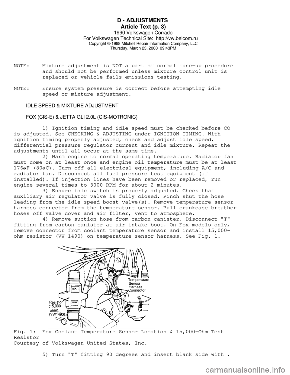
remove connector from coolant temperature sensor and install 15,000-
ohm resistor (VW 1490) on temperature sensor harness. See Fig. 1.Fig. 1: Fox Coolant Temperature Sensor Location & 15,000-Ohm Test
Resistor
Courtesy of Volkswagen United States, Inc.
5) Turn "T" fitting 90 degrees and insert blank side with .
Page 442 of 906

D - ADJUSTMENTS
Article Text (p. 5)
1990 Volkswagen Corrado
For Volkswagen Technical Site: http://vw.belcom.ru
Copyright © 1998 Mitchell Repair Information Company, LLC
Thursday, March 23, 2000 09:43PM
8) Connect adapter between connector and regulator. Connect
multimeter to adapter and turn switch to DCA 200 milliamp-range. Read
and compare current (4-16 milliamps) and CO values to specifications.
Turn engine off.
9) If CO reading is more than 1.2% at current reading of 4-16
milliamps, check for exhaust system leaks, ignition timing, injector
inserts for leaks, and fuel distributor for uneven fuel distribution.
If required, seal injector inserts with sealing compound and tighten
to 15 ft. lbs. (20 N.m).
10) If current reading is less than 4 milliamps or more than
16 milliamps, adjustment must be made with CO adjustment screw as
follows: remove boot from mixture control unit. Center punch hole in
CO adjusting hole and drill a 3/32" hole to a depth of 5/32" (4 mm).
DO NOT drill completely through as adjustment screw will be damaged.
11) Install a 1/8" sheet metal screw and remove plug using
pliers. Start engine and run at idle. Adjust current reading to 10
milliamps by turning CO adjustment screw with Wrench (P 377). Turn
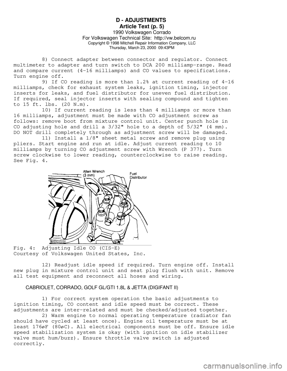
screw clockwise to lower reading, counterclockwise to raise reading.
See Fig. 4.Fig. 4: Adjusting Idle CO (CIS-E)
Courtesy of Volkswagen United States, Inc.
12) Readjust idle speed if required. Turn engine off. Install
new plug in mixture control unit and seat plug flush with unit. Remove
all test equipment and reconnect all hoses and wiring.
CABRIOLET, CORRADO, GOLF GL/GTI 1.8L & JETTA (DIGIFANT II)
1) For correct system operation the basic adjustments to
ignition timing, CO content and idle speed must be correct. These
adjustments are inter-related and must be checked/adjusted together.
2) Warm engine to normal operating temperature (radiator fan
should have cycled at least once). Engine oil temperature must be at
least 176øF (80øC). All electrical components must be off. Ensure idle
speed stabilization system is okay (with ignition on idle stabilizer
valve must hum/buzz). Ensure throttle valve switch is adjusted
correctly.
Page 443 of 906

D - ADJUSTMENTS
Article Text (p. 6)
1990 Volkswagen Corrado
For Volkswagen Technical Site: http://vw.belcom.ru
Copyright © 1998 Mitchell Repair Information Company, LLC
Thursday, March 23, 2000 09:43PM
NOTE: Before checking engine timing, raise engine speed above 2100
RPM at least 4 times. This must be done each time ignition
is turned off and restarted to clear ECU memory and by-pass
hot-start, fast-idle function.
3) Connect an inductive tachometer or Tester (VW 1367) to
alternator, Test Lead (VW 1473) to ignition coil, and timing light
lead to No. 1 spark plug wire. See Fig. 2. Start engine and ensure
engine speed and timing are correct. If not, adjust to specification.
4) Remove the Blue cap from the CO tap tube rising from the
exhaust manifold and connect exhaust gas analyzer. Disconnect the
coolant sensor harness connector. Raise the oil dipstick slightly to
vent crankcase. Disconnect and plug the crankcase ventilation hose.
Start engine and raise engine speed to 2100 RPM at least 4 times.
Check idle, adjust if incorrect. check CO is correct. See IDLE & CO
LEVEL table. If CO adjustment is needed, the idle mixture screw anti-
tamper plug must be remove from the top of the air flow sensor.
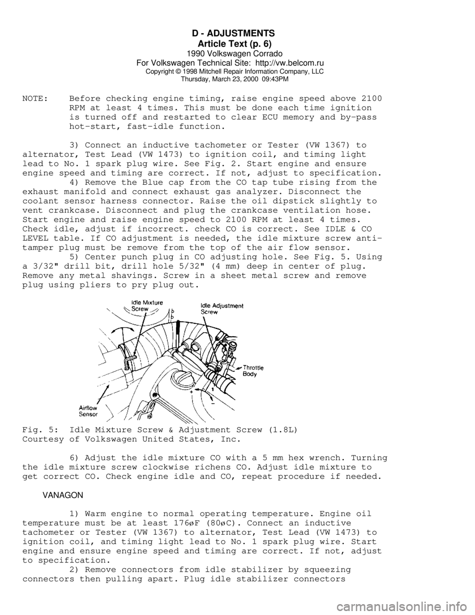
5) Center punch plug in CO adjusting hole. See Fig. 5. Using
a 3/32" drill bit, drill hole 5/32" (4 mm) deep in center of plug.
Remove any metal shavings. Screw in a sheet metal screw and remove
plug using pliers to pry plug out.Fig. 5: Idle Mixture Screw & Adjustment Screw (1.8L)
Courtesy of Volkswagen United States, Inc.
6) Adjust the idle mixture CO with a 5 mm hex wrench. Turning
the idle mixture screw clockwise richens CO. Adjust idle mixture to
get correct CO. Check engine idle and CO, repeat procedure if needed.
VANAGON
1) Warm engine to normal operating temperature. Engine oil
temperature must be at least 176øF (80øC). Connect an inductive
tachometer or Tester (VW 1367) to alternator, Test Lead (VW 1473) to
ignition coil, and timing light lead to No. 1 spark plug wire. Start
engine and ensure engine speed and timing are correct. If not, adjust
to specification.
2) Remove connectors from idle stabilizer by squeezing
connectors then pulling apart. Plug idle stabilizer connectors