1990 VOLKSWAGEN CORRADO oil temperature
[x] Cancel search: oil temperaturePage 564 of 906
FUSES & CIRCUIT BREAKERS
Article Text (p. 2)
1990 Volkswagen Corrado
For Volkswagen Technical Site: http://vw.belcom.ru
Copyright © 1998 Mitchell Repair Information Company, LLC
Thursday, March 23, 2000 09:45PM
Right Tail & Side Lights
8 - 10 Amp
Left Tail & Side Lights
9 - 20 Amp
Rear Window & Mirror Heating
10 - 15 Amp
Foglights
11 - 10 Amp
Left High Beam, High Beam Indicator
12 - 10 Amp
Right High Beam
13 - 10 Amp
Horn, Radiator Fan
14 - 15 Amp
Back-Up Lights, Electric Mirrors, Heated Windshield Washer
Jets
15 - 10 Amp
Engine Electronic
16 - 15 Amp
Warning/Indicator Lights, Multi-Function Indicator, Glove Box
Light, Cassette Storage Light, Rear Spoiler
17 - 10 Amp
Turn Signals
18 - 20 Amp
Fuel Pump, Oxygen Sensor
19 - 30 Amp
Radiator Fan, Air Conditioner
20 - 10 Amp
Brakelights, Cruise Control
21 - 15 Amp
Dome & Luggage Compartment Lights, Cigarette Lighter, Central
Locking System, Multi-Function Indicator
22 - 10 Amp
Radio
CAUTIONS & WARNINGS
ELECTRICAL SHOCK
WARNING: Contact with live components of ignition system while
engine is running could lead to a fatal electric shock.
RADIATOR FAN
Keep hands away from radiator fan. Fan is controlled by a
thermostatic switch which may come on or run for up to 15 minutes even
after engine is turned off.
RADIATOR CAP
CAUTION: Always disconnect the fan motor when working near the
radiator fan. The fan is temperature controlled and could
Page 575 of 906
H - TESTS W/O CODES
Article Text (p. 2)
1990 Volkswagen Corrado
For Volkswagen Technical Site: http://vw.belcom.ru
Copyright © 1998 Mitchell Repair Information Company, LLC
Thursday, March 23, 2000 09:45PM
WILL NOT START OR STARTS HARD COLD (CRANKS OKAY)
* Check ignition fuse (if equipped).
* Check fuel pump fuse and fuel pump relay.
* Verify air intake system is unrestricted.
* Ensure fuel system pressure and volume are correct.
* Check cold start valve and thermo time switch operation.
* Ensure airflow sensor plate is in rest position. Adjust as
necessary.
* Test coolant temperature sensor and wiring. Repair or replace
as required.
* Check for poor ignition ground (1.8L & 2.0L 16-valve engines).
* Check for poor quality or contaminated fuel.
* Check condensation (water) in fuel tank causing fuel pump to
freeze (cold climate).
* Check exhaust system for restriction.
* Test airflow meter. Replace if faulty.
* Ensure sufficient secondary spark is available.
* Check air induction system for cracks or restriction.
* Ensure vacuum hoses are not disconnected or damaged.
* Ensure fuel system residual pressure is correct.
* Ensure fuel injector operation is correct.
* Ensure EGR valve operation is correct and valve closes
completely (if equipped).
* Check for cracks or poor connections at throttle body.
* Ensure ignition and valve timing are correct.
* Check ignition coil primary connections and wiring harness.
* Ensure ignition coil resistance is within specification.
* Check air temperature sensor operation (if equipped).
* Ensure electrical harness and connectors are not broken or loose.
* Ensure ECU or ignition control unit has correct voltage supply
and is properly grounded.
* Ensure engine has sufficient compression.
* Inspect intake air components for leaking hoses, connections or
cracks. Repair as required.
WILL NOT START OR STARTS HARD HOT (CRANKS OKAY)
* Check ignition fuse (if equipped).
* Check fuel system fuse and fuel pump relay.
* Check for poor quality or contaminated fuel.
* Check condensation (water) in fuel tank causing fuel pump to
freeze (cold climate).
* Check exhaust system for restriction.
* Check cold start valve and thermo time switch operation.
* Check fuel system and control system pressure. Replace pressure
regulator if necessary.
* Check residual fuel pressure. Replace fuel pump check valve or
fuel accumulator as necessary.
* Check oxygen sensor system operation.
* Ensure airflow sensor plate is in rest position. Adjust as
Page 576 of 906
H - TESTS W/O CODES
Article Text (p. 3)
1990 Volkswagen Corrado
For Volkswagen Technical Site: http://vw.belcom.ru
Copyright © 1998 Mitchell Repair Information Company, LLC
Thursday, March 23, 2000 09:45PM
necessary.
* Ensure injector spray patterns and volume are correct. Replace
faulty injectors.
* Inspect fuel lines and connections for leaks.
* Check carbon canister solenoid valves (CIS-E Motronic).
* Test airflow meter. Replace if faulty.
* Ensure sufficient secondary spark is available.
* Check air induction system for cracks or restriction.
* Check airflow sensor plate rest position.
* Ensure vacuum hoses are not disconnected or damaged.
* Ensure EGR valve operation is correct and valve closes
completely (if equipped).
* Check for cracks or poor connections at throttle body.
* Ensure ignition and valve timing are correct.
* Check ignition coil primary connections and wiring harness.
* Ensure ignition coil resistance is within specification.
* Check air temperature sensor operation.
* Check coolant temperature sensor operation.
* Ensure electrical harness and connectors are not broken or loose.
* Ensure ECU or ignition control unit has correct voltage supply
and is properly grounded.
* Ensure engine has sufficient compression.
ENGINE STALLS OR IDLES ROUGH
* Check fuel system and control system pressure. Replace pressure
regulator if necessary.
* Check cold start valve for leaking (engine warm).
* Ensure injector spray patterns and volume are correct. Replace
faulty injectors.
* Test coolant temperature sensor and wiring. Repair or replace
as required.
* Inspect intake air components for leaking hoses, connections or
cracks. Repair as required.
* Ensure airflow sensor plate movement and rest position. Adjust
as necessary.
* Test idle switch and idle air stabilizer valve.
* Perform system electrical checks.
* Check airflow meter. Replace if faulty.
* Ensure idle RPM is correct.
* Check auxiliary air by-pass regulator.
* Check fuel injector electrical connections.
* Use stethoscope to verify fuel injectors are operating.
* Ensure sufficient secondary spark is available in all cylinders.
* Verify vacuum hose routing is correct and there are no
vacuum leaks.
* Check idle stabilizer operation.
* Check for EGR system malfunction (if equipped).
* Check O2 sensor operation.
* Check for distortion or cracks in fuel injector(s) plastic
connecting flange(s).
* Check for use of poor quality fuel containing insufficient
Page 588 of 906

I - SYSTEM/COMPONENT TESTS
Article Text
1990 Volkswagen Corrado
For Volkswagen Technical Site: http://vw.belcom.ru
Copyright © 1998 Mitchell Repair Information Company, LLC
Thursday, March 23, 2000 09:46PM
ARTICLE BEGINNING
1990 ENGINE PERFORMANCE
Systems & Component Testing
Volkswagen; Cabriolet, Corrado, Fox, Golf GL/GTI,
Jetta, Vanagon
INTRODUCTION
Before testing separate components or systems, perform
procedures in F - BASIC TESTING and H - TESTS W/O CODES articles.
NOTE: Testing individual components does not isolate shorts or
opens. Perform all voltage tests with a Digital
Volt-Ohmmeter (DVOM) with a minimum 10-megohm input
impedance, unless stated otherwise in test procedure. Use
ohmmeter to isolate wiring harness shorts or opens.
AIR INDUCTION SYSTEMS (SUPERCHARGER)
BOOST PRESSURE
1) Before checking supercharger boost pressure, ensure engine
idle speed is correct. See D - ADJUSTMENTS article. Ensure engine oil
temperature is 176øF (80øC). Check knock sensor operation. See KNOCK
SENSOR under IDLE CONTROL SYSTEM in this article.
2) Connect Pressure Gauge (VW1397) or equivalent to the
pressure regulator hose using adapter "T". Open pressure gauge check
valve to position "A" and start engine.
3) Remove harness connector from CO potentiometer and Blue
connector from temperature sensor (in front flange on cylinder head).
Accelerate to full throttle. Engine speed must increase periodically
then drop (surge). Watch pressure gauge, boost pressure must reach 8.7
psi (0.6 kg/cm
ý). If boost does not reach specification, check for
leaks in air system and correct by-pass valve setting. Check
supercharger.
COMPUTERIZED ENGINE CONTROLS
NOTE: For fuel system used on model being tested, see FUEL SYSTEM
APPLICATION table.
FUEL SYSTEM APPLICATION
ÄÄÄÄÄÄÄÄÄÄÄÄÄÄÄÄÄÄÄÄÄÄÄÄÄÄÄÄÄÄÄÄÄÄÄÄÄÄÄÄÄÄÄÄÄÄÄÄÄÄÄÄÄÄÄÄÄÄÄÄÄÄÄÄÄÄÄÄÄÄApplication Fuel System
Cabriolet, Corrado, Golf GL/GTI,
Jetta & Vanagon .................................. AFC-Digifant II
Fox .......................................................... CIS-E
Jetta GLi ............................................. CIS-Motronic
Page 597 of 906
I - SYSTEM/COMPONENT TESTS
Article Text (p. 10)
1990 Volkswagen Corrado
For Volkswagen Technical Site: http://vw.belcom.ru
Copyright © 1998 Mitchell Repair Information Company, LLC
Thursday, March 23, 2000 09:46PM
FUEL CONTROL
COLD START VALVE (ALL MODELS EXCEPT VANAGON)
1) Engine temperature must be below 85øF (30øC). Disconnect
cold start valve attaching screws and remove valve with harness
connector and fuel line attached.
2) Remove ignition coil secondary wire and jumper to ground.
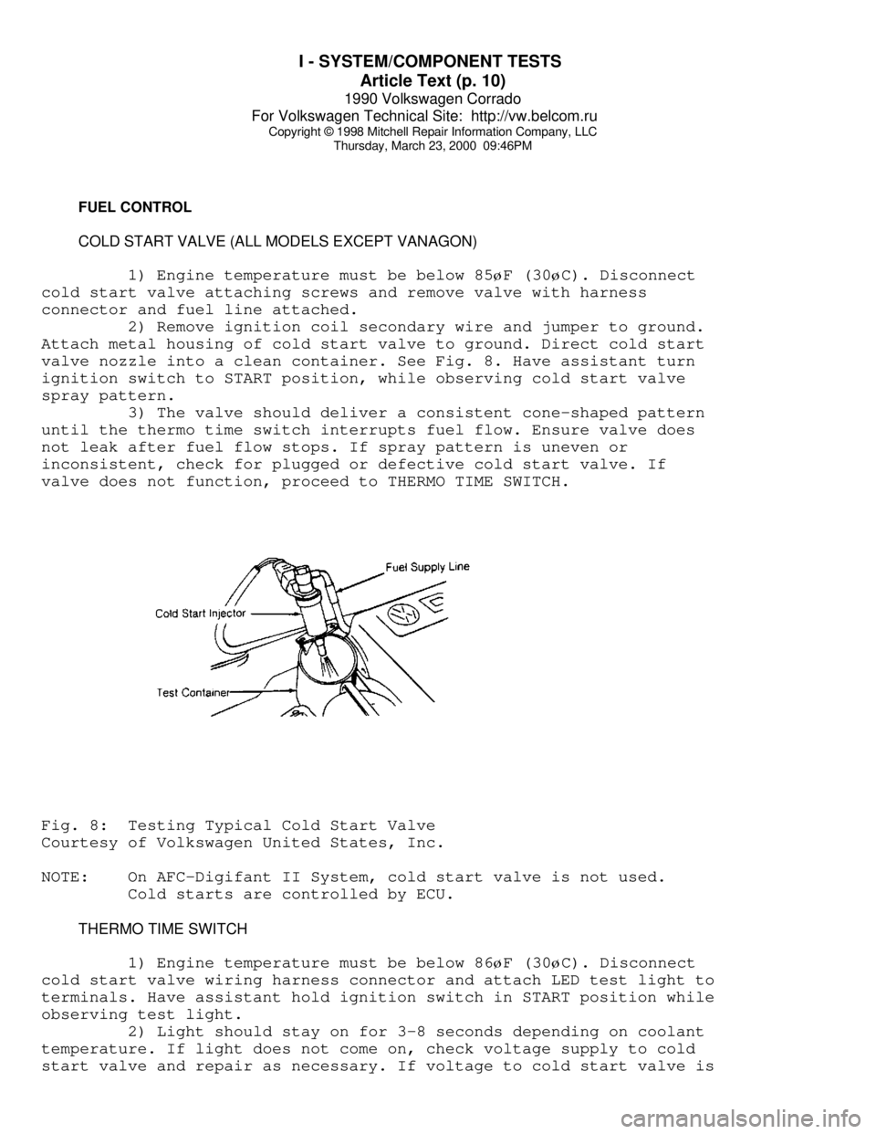
Attach metal housing of cold start valve to ground. Direct cold start
valve nozzle into a clean container. See Fig. 8. Have assistant turn
ignition switch to START position, while observing cold start valve
spray pattern.
3) The valve should deliver a consistent cone-shaped pattern
until the thermo time switch interrupts fuel flow. Ensure valve does
not leak after fuel flow stops. If spray pattern is uneven or
inconsistent, check for plugged or defective cold start valve. If
valve does not function, proceed to THERMO TIME SWITCH.Fig. 8: Testing Typical Cold Start Valve
Courtesy of Volkswagen United States, Inc.
NOTE: On AFC-Digifant II System, cold start valve is not used.
Cold starts are controlled by ECU.
THERMO TIME SWITCH
1) Engine temperature must be below 86
øF (30øC). Disconnect
cold start valve wiring harness connector and attach LED test light to
terminals. Have assistant hold ignition switch in START position while
observing test light.
2) Light should stay on for 3-8 seconds depending on coolant
temperature. If light does not come on, check voltage supply to cold
start valve and repair as necessary. If voltage to cold start valve is
Page 603 of 906
INSTRUMENT PANEL
Article Text
1990 Volkswagen Corrado
For Volkswagen Technical Site: http://vw.belcom.ru
Copyright © 1998 Mitchell Repair Information Company, LLC
Thursday, March 23, 2000 09:46PM
ARTICLE BEGINNING
1989-90 ACCESSORIES & EQUIPMENT
Volkswagen Instrument Panels
Cabriolet, Fox, Golt, GTI, Jetta, Jetta GLI, Vanagon
DESCRIPTION & OPERATION
Instrument cluster for most models includes speedometer, fuel
gauge and temperature gauge. Optional instruments include clock,
tachometer, voltmeter and oil temperature gauge.
Printed circuit provides voltage to gauges. A voltage
regulator attached to the printed circuit controls voltage to fuel and
temperature gauges. Light Emitting Diodes (LEDs) are used for most
warning lights. To replace diodes, pull from printed circuit sockets.
NOTE: Volkswagen Tester (1301) is required for resistance tests.
Tester settings are numerical. Settings do not indicate
resistance in ohms. Manufacturer does not supply resistance
value in ohms.
TESTING
FUEL & TEMPERATURE GAUGE
1) Disconnect wire from fuel tank or temperature sending
unit. Connect VW tester between wire and ground. Turn ignition on and
allow 2 minutes for gauge reading to stabilize. Use FUEL GAUGE TESTING
or TEMPERATURE GAUGE TESTING table to compare gauge reading. Gauge
should be within one pointer width of specification.
2) If gauge needle does not move, check continuity between
sender wire and gauge. If needle moves, but does not match
specifications, replace gauge. If gauge works correctly with tester,
but not sending unit, replace sending unit.
FUEL GAUGE TESTINGÄÄÄÄÄÄÄÄÄÄÄÄÄÄÄÄÄÄÄÄÄÄÄÄÄÄÄÄÄÄÄÄÄÄÄÄÄÄÄÄÄÄÄÄÄÄÄÄÄÄÄÄÄÄÄApplication Dial Setting Indicator
Cabriolet & Fox .......... 55 ................ Full
560 ................Empty
Golf, GTI, Jetta
& Jetta GLI .............. 52 ................ Full
550 ................Empty
Vanagon .................. 50 ................ Full
320 ................Empty
ÄÄÄÄÄÄÄÄÄÄÄÄÄÄÄÄÄÄÄÄÄÄÄÄÄÄÄÄÄÄÄÄÄÄÄÄÄÄÄÄÄÄÄÄÄÄÄÄÄÄÄÄÄÄÄTEMPERATURE GAUGE TESTING
ÄÄÄÄÄÄÄÄÄÄÄÄÄÄÄÄÄÄÄÄÄÄÄÄÄÄÄÄÄÄÄÄÄÄÄÄÄÄÄÄÄÄÄÄÄÄÄÄÄÄÄÄÄÄÄ
Page 638 of 906
MAINTENANCE INFORMATION
Article Text (p. 3)
1990 Volkswagen Corrado
For Volkswagen Technical Site: http://vw.belcom.ru
Copyright © 1998 Mitchell Repair Information Company, LLC
Thursday, March 23, 2000 09:48PM
Severe Service (Unique Driving Conditions)
* Short Trips In Freezing Temperatures
* Towing Or Heavily Loaded
* Severe Dust Conditions
* Hot Weather, Stop-And-Go Driving
* Extensive Idling
CAMSHAFT TIMING BELT
CAUTION: Failure to replace a faulty camshaft timing belt may result
in serious engine damage.
The condition of camshaft drive belts should always be
checked on vehicles which have more than 50,000 miles. Although some
manufacturers do not recommend belt replacement at a specified
mileage, others require it at 60,000-100,000 miles. A camshaft drive
belt failure may cause extensive damage to internal engine components
on most engines, although some designs do not allow piston-to-valve
contact. These designs are often called "Free Wheeling".
Many manufacturers changed their maintenance and warranty
schedules in the mid-1980's to reflect timing belt inspection and/or
replacement at 50,000-60,000 miles. Most service interval schedules in
this manual reflect these changes.
Belts or components should be inspected and replaced if any
of the following conditions exist:
* Cracks Or Tears In Belt Surface
* Missing, Damaged, Cracked Or Rounded Teeth
* Oil Contamination
* Damaged Or Faulty Tensioners
* Incorrect Tension Adjustment
Inspect camshaft timing belt condition every 20,000 miles.
Replace belt as necessary.
DRIVE BELT ROUTINGFig. 1: Drive Belt Tensioner Adjustment (VR6)
Courtesy of Volkswagen United States, Inc.
Page 645 of 906
MAINTENANCE INFORMATION
Article Text (p. 10)
1990 Volkswagen Corrado
For Volkswagen Technical Site: http://vw.belcom.ru
Copyright © 1998 Mitchell Repair Information Company, LLC
Thursday, March 23, 2000 09:48PM
SERVICE LABOR TIMES
SERVICE LABOR TIMES TABLE (HOURS)ÄÄÄÄÄÄÄÄÄÄÄÄÄÄÄÄÄÄÄÄÄÄÄÄÄÄÄÄÄÄÄÄÄÄÄÄÄÄÄÄÄÄÄÄÄÄÄÄÄÄÄÄÄÄÄÄÄÄÄÄÄÄÄÄÄ (1)(2) 15,000 (1)(2) 30,000 (60,000)
Application Mile Service Mile Service
Automatic Transmission ..... 1.6 .................. 3.3 (4.2)
Manual Transmission ........ 1.8 .................. 2.7 (3.6)
(1) - Add .2 hr. if equipped with A/C. Add .1 hr. if equipped
with cruise control.
(2) - Add 1.8 hrs. to replace camshaft timing belt (if equipped).
ÄÄÄÄÄÄÄÄÄÄÄÄÄÄÄÄÄÄÄÄÄÄÄÄÄÄÄÄÄÄÄÄÄÄÄÄÄÄÄÄÄÄÄÄÄÄÄÄÄÄÄÄÄÄÄÄÄÄÄÄÄÄÄÄÄ LUBRICATION SPECIFICATIONS
LUBRICATION SPECIFICATIONS TABLE
ÄÄÄÄÄÄÄÄÄÄÄÄÄÄÄÄÄÄÄÄÄÄÄÄÄÄÄÄÄÄÄÄÄÄÄÄÄÄÄÄÄÄÄÄÄÄÄÄÄÄÄÄÄÄÄÄÄÄÄÄÄÄÄÄÄApplication Fluid Specifications
Engine Oil (1)
Ambient Temperatures
Greater Than 50
øF (10øC) .............. SAE 20W-50 API SF/CD
14
øF To 50øF (-10øC To +10øC) ......... SAE 10W-40 API SF/CD
Less Than 14
øF (-10ø C) ................ SAE 5W-30 API SF/CD
Brake Fluid ........................ SAE J1703 (DOT 3 Or DOT 4)
Power Steering Fluid ......................... VW Hydraulic Oil
(G 002000) Or Equivalent
Automatic Transmission ........... Dexron-IIE ATF Or Equivalent
Manual Transaxle .......................... SAE 80W API GL-4 Or
SAE 75W-90 (G50 Synthetic Gear Oil)
Final Drive (A/T & M/T)
(Differential) .......... SAE 75W-90 (G50 Synthetic Gear Oil)
Wheel Bearings .................... NLGI Grade 2 Category GC-LB
Drive Shaft U-Joints .............. NLGI Grade 2 Category GC-LB
Steering Linkage (2)(3) ........... NLGI Grade 2 Category GC-LB
Ball Joints (2)(4) ................ NLGI Grade 2 Category GC-LB
Weatherstrip ....................... Dielectric Silicone Grease
(1) - SAE 15W-40 or 20W-40 engine oil is recommended for extreme
conditions or extended highway operation.
(2) - Use low pressure grease gun to prevent seal damage.
(3) - Fill until lubricant squeezes out from the base of seals.
(4) - Fill ball joint until seal starts to swell.
ÄÄÄÄÄÄÄÄÄÄÄÄÄÄÄÄÄÄÄÄÄÄÄÄÄÄÄÄÄÄÄÄÄÄÄÄÄÄÄÄÄÄÄÄÄÄÄÄÄÄÄÄÄÄÄÄÄÄÄÄÄÄÄÄÄ FLUID CAPACITIES
FLUID CAPACITIES TABLE
ÄÄÄÄÄÄÄÄÄÄÄÄÄÄÄÄÄÄÄÄÄÄÄÄÄÄÄÄÄÄÄÄÄÄÄÄÄÄÄÄÄÄÄÄÄÄÄÄÄÄÄÄÄÄÄÄÄÄÄÄÄÄÄÄÄ