1990 VOLKSWAGEN CORRADO oil temperature
[x] Cancel search: oil temperaturePage 453 of 906
E - THEORY/OPERATION - DIGIFANT
Article Text (p. 3)
1990 Volkswagen Corrado
For Volkswagen Technical Site: http://vw.belcom.ru
Copyright © 1998 Mitchell Repair Information Company, LLC
Thursday, March 23, 2000 09:43PM
the following:
* Coolant Temperature Sensor
* ECU Control Relay
* ECU
* Oxygen Sensor
* Power Steering Oil Pressure Switch
NOTE: Components are grouped into 2 categories. The first category
covers INPUT DEVICES, which control or produce voltage
signals monitored by the control unit. The second category
covers OUTPUT SIGNALS, which are components controlled by
the control unit.
INPUT DEVICES
AIRFLOW SENSOR (EXCEPT CORRADO)
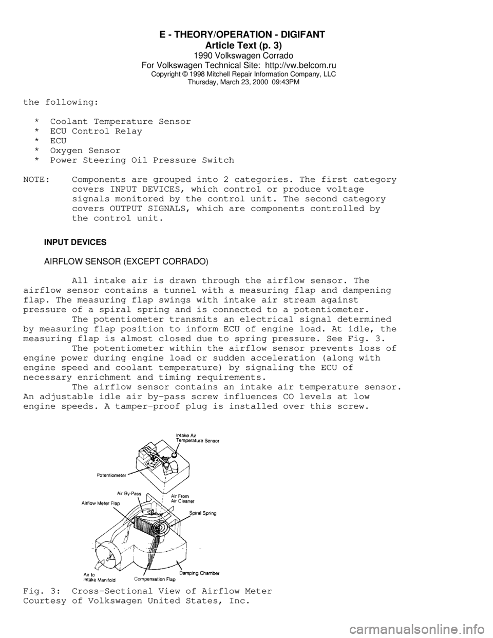
All intake air is drawn through the airflow sensor. The
airflow sensor contains a tunnel with a measuring flap and dampening
flap. The measuring flap swings with intake air stream against
pressure of a spiral spring and is connected to a potentiometer.
The potentiometer transmits an electrical signal determined
by measuring flap position to inform ECU of engine load. At idle, the
measuring flap is almost closed due to spring pressure. See Fig. 3.
The potentiometer within the airflow sensor prevents loss of
engine power during engine load or sudden acceleration (along with
engine speed and coolant temperature) by signaling the ECU of
necessary enrichment and timing requirements.
The airflow sensor contains an intake air temperature sensor.
An adjustable idle air by-pass screw influences CO levels at low
engine speeds. A tamper-proof plug is installed over this screw.Fig. 3: Cross-Sectional View of Airflow Meter
Courtesy of Volkswagen United States, Inc.
Page 455 of 906

E - THEORY/OPERATION - DIGIFANT
Article Text (p. 5)
1990 Volkswagen Corrado
For Volkswagen Technical Site: http://vw.belcom.ru
Copyright © 1998 Mitchell Repair Information Company, LLC
Thursday, March 23, 2000 09:43PM
OXYGEN (O2) SENSOR
The O2 sensor detects oxygen content in the exhaust gas and
sends this information to the ECU. In operation, the ECU receives
signals from the O2 sensor and varies the duration during which fuel
is injected. A high voltage signal indicates a rich mixture. A low
voltage signal indicates a lean mixture.
The O2 sensor is heated electrically for rapid warm-up and
constant operating temperature. Power to the heating element is
supplied whenever ignition switch is turned to ON position.
POWER STEERING (P/S) OIL PRESSURE SWITCH
The P/S oil pressure switch signals the ECU when the power
steering load is high. The ECU then sends a voltage signal to the idle
stabilization valve to increase idle speed with power steering load.
THROTTLE VALVE SWITCH (VANAGON ONLY)
Throttle valve switch supplies ECU with information that
throttle valve is closed. If engine is above 1500 RPM with throttle
closed, fuel will be shut off to the injectors. At idle speed, this
switch signals control unit to regulate amount of fuel injected.
OUTPUT SIGNALS
NOTE: Each vehicle may be equipped with different combinations of
computer controlled components. The following listed
components may NOT be used on all models. For theory and
operation on each output component, refer to the system
indicated in brackets, to the right of each component.
* Fuel Injectors (Fuel Control)
* Idle Air Stabilizer Valve (Idle Speed)
* Ignition Coil Control (Ignition System)
FUEL DELIVERY
ELECTRIC FUEL PUMP
The fuel pump provides fuel under pressure to the fuel
pressure regulator. Power for operation during cranking mode is
provided from starter relay via the fuel pump relay. After the engine
has started, control of the fuel pump is through the ignition signal.
The fuel pump is sealed unit.
FUEL PUMP RELAY
When energized by the ignition switch and grounded by the
ECU. The fuel pump relay provides battery voltage to the fuel pumps,
injectors, idle stabilization control unit, oxygen sensor heating
Page 456 of 906

E - THEORY/OPERATION - DIGIFANT
Article Text (p. 6)
1990 Volkswagen Corrado
For Volkswagen Technical Site: http://vw.belcom.ru
Copyright © 1998 Mitchell Repair Information Company, LLC
Thursday, March 23, 2000 09:43PM
element and the power steering pressure switch.
FUEL PRESSURE REGULATOR
The fuel pressure regulator is a sealed, spring loaded
diaphragm with connection for intake manifold vacuum. Fuel pressure is
maintained at about 36 psi (2.5 kg/cmý) pressure.
A connection for intake manifold vacuum provides a constant
pressure differential which ensures that the amount of fuel injected
is solely dependent upon injector open ON time. Excess fuel is
returned to fuel tank. No service of pressure regulator is required.
The pressure regulator is located on or near fuel rail.
FUEL CONTROL
Data on engine temperature, engine speed, intake air volume,
throttle position, exhaust oxygen content and intake air temperature
are used by ECM to determine injection pulse width.
FUEL INJECTORS
A fuel rail links the fuel pressure regulator with the fuel
injectors. Each cylinder is provided with a solenoid-operated injector
which sprays fuel toward backside of each inlet valve. Each injector
is energized through the ignition coil and grounded through the ECU to
complete the circuit
Each injector is linked to a resistor (resistor may be
external or integral with injector or ECU) to reduce operating voltage
to 3 volts and to protect injectors from power surges. The ECU
controls length of time each injector is open. The ON time of the
injector governs the amount of fuel delivered. The injector delivers
1/2 the amount of fuel required for an operating cycle each time they
open (twice per cycle).
FUEL PUMP AFTER-RUN RELAY (CORRADO)
The purpose of the After-Run Fuel Pump relay system is to
reduce the chance of fuel vaporizing in fuel rail. Both transfer pump
and fuel pump are used to recirculate fuel. The after-run relay
switches the pumps on for 2 minutes after ignition is turned off or
when under hood temperature exceeds 194
ø F (90ø C) and fuel pressure
is above 17 psi (1.2 kg/cm
ý). The pumps operate a maximum of 8
minutes.
IDLE SPEED
Engine idle speed is controlled by the ECU and idle speed
control unit depending upon engine operating conditions. The ECU and
Idle speed control unit are fed information on engine operating
conditions and determine the best idle speed.
IDLE AIR STABILIZER VALVE
Page 457 of 906

E - THEORY/OPERATION - DIGIFANT
Article Text (p. 7)
1990 Volkswagen Corrado
For Volkswagen Technical Site: http://vw.belcom.ru
Copyright © 1998 Mitchell Repair Information Company, LLC
Thursday, March 23, 2000 09:43PM
The idle air stabilizer valve is ECU controlled. On Vanagon
idle stabilizer valve is controlled by a separate idle stabilizer
controller. The idle air stabilizer operates to continuously maintains
engine idle at a computed engine idle speed.
IGNITION SYSTEM
The Hall Effect sending unit in the distributor, uses a
shutter window wheel mounted on the distributor shaft. The shutter
blades pass in and out of the air gap of the hall effect sender
resulting in signal pulses (engine speed signal). There is one shutter
window for each engine cylinder. Signals from distributor hall sender
are sent to the ECU.
ELECTRONIC IGNITION SYSTEM
IGNITION COIL CONTROL
Signals from distributor hall sender are sent to the ECU,
which produces a pulsating signal to the ignition coil. This computed
signal from ECU to ignition coil, control ignition timing according to
engine load (airflow sensor signal), engine speed (Hall Effect signal)
and engine coolant temperature.
IGNITION TIMING ADVANCE CONTROL SYSTEM
Timing is ECU controlled.
EMISSION SYSTEMS
EVAPORATIVE EMISSIONS SYSTEM
Fuel vapors are collected in the expansion tank. Any liquid
gasoline collect in expansion tank flows back to the fuel tank through
vent lines. See Fig. 4. Fuel vapors are drawn from tops of the
expansion tanks and flow into the carbon canister where the vapors are
stored. When the engine is not running.
After engine is started, the control valve is opened by
throttle vacuum. Fresh air is drawn into bottom of the canister. Fuel
vapors from the canister are drawn into the intake manifold.
EXHAUST GAS RECIRCULATION
Information is not available. See M - VACUUM DIAGRAMS for
system components and vacuum hose routings.
Page 487 of 906

ELECTRICAL COMPONENT LOCATOR
Article Text (p. 28)
1990 Volkswagen Corrado
For Volkswagen Technical Site: http://vw.belcom.ru
Copyright © 1998 Mitchell Repair Information Company, LLC
Thursday, March 23, 2000 09:44PM
Fuel Gauge Sending Unit Mounted in top of fuel tank.
Hall Speed Sensor Rear of instrument cluster.
Heated Seat Temperature Sensor Below lower cushion of each
seat.Knock Sensor Mounted on cylinder block,
near dipstick.
Manifold Pressure Sensor In Digifant control unit,
below fresh air intake on
firewall.
Multi-Function Indicator
Vacuum Sensor Round sensor mounted on rear
of instrument cluster.
Oil Temperature Sending Unit Small sending unit above oil
filter (Green/Black wire
connector).
Oxygen Sensor In exhaust pipe, near
catalytic converter.
Vehicle Speed Sensor On transaxle.
Page 514 of 906
ENGINE OVERHAUL PROCEDURES - GENERAL INFORMATION
Article Text (p. 5)
1990 Volkswagen Corrado
For Volkswagen Technical Site: http://vw.belcom.ru
Copyright © 1998 Mitchell Repair Information Company, LLC
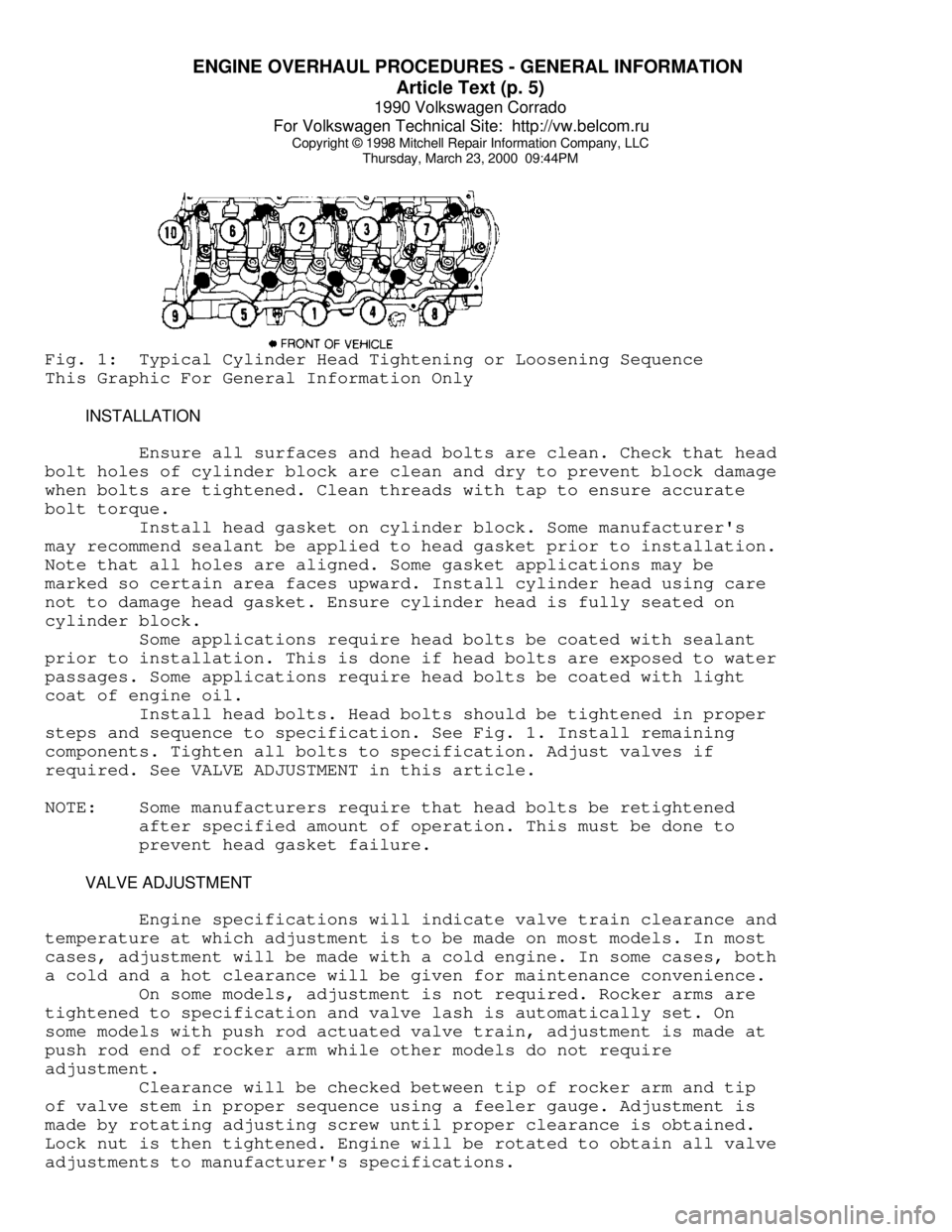
Thursday, March 23, 2000 09:44PMFig. 1: Typical Cylinder Head Tightening or Loosening Sequence
This Graphic For General Information Only
INSTALLATION
Ensure all surfaces and head bolts are clean. Check that head
bolt holes of cylinder block are clean and dry to prevent block damage
when bolts are tightened. Clean threads with tap to ensure accurate
bolt torque.
Install head gasket on cylinder block. Some manufacturer's
may recommend sealant be applied to head gasket prior to installation.
Note that all holes are aligned. Some gasket applications may be
marked so certain area faces upward. Install cylinder head using care
not to damage head gasket. Ensure cylinder head is fully seated on
cylinder block.
Some applications require head bolts be coated with sealant
prior to installation. This is done if head bolts are exposed to water
passages. Some applications require head bolts be coated with light
coat of engine oil.
Install head bolts. Head bolts should be tightened in proper
steps and sequence to specification. See Fig. 1. Install remaining
components. Tighten all bolts to specification. Adjust valves if
required. See VALVE ADJUSTMENT in this article.
NOTE: Some manufacturers require that head bolts be retightened
after specified amount of operation. This must be done to
prevent head gasket failure.
VALVE ADJUSTMENT
Engine specifications will indicate valve train clearance and
temperature at which adjustment is to be made on most models. In most
cases, adjustment will be made with a cold engine. In some cases, both
a cold and a hot clearance will be given for maintenance convenience.
On some models, adjustment is not required. Rocker arms are
tightened to specification and valve lash is automatically set. On
some models with push rod actuated valve train, adjustment is made at
push rod end of rocker arm while other models do not require
adjustment.
Clearance will be checked between tip of rocker arm and tip
of valve stem in proper sequence using a feeler gauge. Adjustment is
made by rotating adjusting screw until proper clearance is obtained.
Lock nut is then tightened. Engine will be rotated to obtain all valve
adjustments to manufacturer's specifications.
Page 545 of 906

ENGINE OVERHAUL PROCEDURES - GENERAL INFORMATION
Article Text (p. 36)
1990 Volkswagen Corrado
For Volkswagen Technical Site: http://vw.belcom.ru
Copyright © 1998 Mitchell Repair Information Company, LLC
Thursday, March 23, 2000 09:44PM
to ensure correct amount of oil has filled crankcase. Check oil level
while pre-oiling.
If pressure oiler is not available, disconnect ignition
system. Remove oil pressure sending unit and replace with oil pressure
test gauge. Using starter motor, rotate engine starter until gauge
shows normal oil pressure for several seconds. DO NOT crank engine
for more than 30 seconds to avoid starter motor damage.
Ensure oil pressure has reached the most distant point from
the oil pump. Reinstall oil pressure sending unit. Reconnect ignition
system.
INITIAL START-UP
Start the engine and operate engine at low speed while
checking for coolant, fuel and oil leaks. Stop engine. Recheck coolant
and oil level. Adjust if necessary.
CAMSHAFT
Break-in procedure is required when a new or reground
camshaft has been installed. Operate and maintain engine speed between
1500-2500 RPM for approximately 30 minutes. Procedure may vary due to
manufacturers recommendations.
PISTON RINGS
Piston rings require a break-in procedure to ensure seating
of rings to cylinder walls. Serious damage may occur to rings if
correct procedures are not followed.
Extremely high piston ring temperatures are produced obtained
during break-in process. If rings are exposed to excessively high RPM
or high cylinder pressures, ring damage can occur. Follow piston ring
manufacturer's recommended break-in procedure.
FINAL ADJUSTMENTS
Check or adjust ignition timing and dwell (if applicable).
Adjust valves (if necessary). Adjust carburetion or injection idle
speed and mixture. Retighten cylinder heads (if required). If
cylinder head or block is aluminum, retighten bolts when engine is
cold. Follow the engine manufacturer's recommended break-in procedure
and maintenance schedule for new engines.
NOTE: Some manufacturer's require that head bolts be retightened
after specified amount of operation. This must be done to
prevent head gasket failure.
END OF ARTICLE
Page 558 of 906

F - BASIC TESTING
Article Text (p. 13)
1990 Volkswagen Corrado
For Volkswagen Technical Site: http://vw.belcom.ru
Copyright © 1998 Mitchell Repair Information Company, LLC
Thursday, March 23, 2000 09:44PM
DISTRIBUTOR
HALL EFFECT SENDER
1) Remove coil secondary and attach to ground. Disconnect
Hall Effect sender wire at the distributor. Using a LED Test Light (US
1115), check for voltage between outer terminals of connector. See
Fig. 5 or 8. With ignition on, light should be on. If not, check
wiring for short or open circuit. If wiring is okay, replace Digifant
control unit.
2) If light came on in step 1), reconnect Hall Effect sender
harness connector. Pull back Hall Effect sender boot to expose contact
terminals. Apply LED Test Light (US 1115) probe to center contact and
battery positive terminal. See Fig. 5. Observe test light while
cranking engine. If test light blinks, Hall Effect sender is okay. If
not, replace Hall Effect-sender.
IDLE SPEED, CO LEVEL & IGNITION TIMING
Ensure idle speed, CO level and base ignition timing are set
to specification. If necessary, see ON-VEHICLE ADJUSTMENTS article.
IDLE SPEED & CO LEVEL TABLEÄÄÄÄÄÄÄÄÄÄÄÄÄÄÄÄÄÄÄÄÄÄÄÄÄÄÄÄÄÄÄÄÄÄÄÄÄÄÄÄÄÄÄÄÄÄÄÄÄÄÄÄÄÄÄÄÄÄÄÄApplication Idle RPM CO Level %
All Models ............ 800-1000 .............. 0.3-1.2%
ÄÄÄÄÄÄÄÄÄÄÄÄÄÄÄÄÄÄÄÄÄÄÄÄÄÄÄÄÄÄÄÄÄÄÄÄÄÄÄÄÄÄÄÄÄÄÄÄÄÄÄÄÄÄÄÄÄÄÄÄIGNITION TIMING TABLE (Degrees BTDC @ RPM)
ÄÄÄÄÄÄÄÄÄÄÄÄÄÄÄÄÄÄÄÄÄÄÄÄÄÄÄÄÄÄÄÄÄÄÄÄÄÄÄÄÄÄÄÄÄÄÄÄÄÄÄÄÄÄÄÄÄÄÄÄApplication Checking Adjusting
1.8L ............... 4-8 @ 2250-2350 . 5-7 @ 2250-2350
2.0L ................ 4-8 @ 770-830 ...... 5-7 @ 770-830
2.1L (1) ........... 4-8 @ 2250-2350 . 5-7 @ 2250-2350
(1) - With coolant temperature sensor disconnected.
ÄÄÄÄÄÄÄÄÄÄÄÄÄÄÄÄÄÄÄÄÄÄÄÄÄÄÄÄÄÄÄÄÄÄÄÄÄÄÄÄÄÄÄÄÄÄÄÄÄÄÄÄÄÄÄÄÄÄÄÄ SUMMARY
If no faults were found while performing F - BASIC TESTING,
proceed to H - TESTS W/CODES article for diagnosis by symptom (i.e.,
ROUGH IDLE, NO START, etc.) or intermittent diagnostic procedures.
END OF ARTICLE