1990 VOLKSWAGEN CORRADO door lock
[x] Cancel search: door lockPage 83 of 906

* ELECTRICAL SYSTEM UNIFORM INSPECTION GUIDELINES *
Article Text (p. 18)
1990 Volkswagen Corrado
For Volkswagen Technical Site: http://vw.belcom.ru
Copyright © 1998 Mitchell Repair Information Company, LLC
Thursday, March 23, 2000 09:29PM
terminals ³ ³
ÄÄÄÄÄÄÄÄÄÄÄÄÄÄÄÄÄÄÄÄÄ´
³Damaged
³ ³
ÄÄÄÄÄÄÄÄÄÄÄÄÄÄÄÄÄÄÄÄÄÁÄÄÄÄÄÄÄÄÄÄÄÄÄÄÄÄÄÄÄÄÄÄÁÄÄÄÄÄÄÄÄÄÄÄÄÄÄÄÄÄÄÄÄÄÄÄÄÄ VEHICLE ACCESSORIES
Vehicle accessories refers to OEM installed equipment,
including but not limited to power windows, locks, seats, roof/top,
antennas, heated seats, mirrors, windshield/window defrosters, trunk
pull down/release, keyless entry, tire pressure monitors, electric
mirrors, etc.
POWER LOCKS, WINDOWS, SEATS, MIRRORS, ROOF/TOPS, ANTENNAS,
SLIDING DOORS
SWITCHES
ÄÄÄÄÄÄÄÄÄÄÄÄÄÄÄÄÄÄÄÄÄÄÄÄÄÄÄÄÄÄÄÄÄÄÄÄÄÂÄÄÄÄÄÄÄÄÄÄÄÄÄÄÄÄÄÄÄÄÄÄÄÄÄÄÄÄÄÄÄÄCondition
³ Procedure
ÄÄÄÄÄÄÄÄÄÄÄÄÄÄÄÄÄÄÄÄÄÄÄÄÄÄÄÄÄÄÄÄÄÄÄÄÄÅÄÄÄÄÄÄÄÄÄÄÄÄÄÄÄÄÄÄÄÄÄÄÄÄÄÄÄÄÄÄÄÄInoperable
³ Require replacement.
ÄÄÄÄÄÄÄÄÄÄÄÄÄÄÄÄÄÄÄÄÄÄÄÄÄÄÄÄÄÄÄÄÄÄÄÄÄÅÄÄÄÄÄÄÄÄÄÄÄÄÄÄÄÄÄÄÄÄÄÄÄÄÄÄÄÄÄÄÄÄIntermittent
³ Suggest replacement.
ÄÄÄÄÄÄÄÄÄÄÄÄÄÄÄÄÄÄÄÄÄÄÄÄÄÄÄÄÄÄÄÄÄÄÄÄÄÅÄÄÄÄÄÄÄÄÄÄÄÄÄÄÄÄÄÄÄÄÄÄÄÄÄÄÄÄÄÄÄÄMalfunctioning (e.g.,binding, worn,
³ Suggest repair or replacement.
won't return, etc.)
³
ÄÄÄÄÄÄÄÄÄÄÄÄÄÄÄÄÄÄÄÄÄÄÄÄÄÄÄÄÄÄÄÄÄÄÄÄÄÅÄÄÄÄÄÄÄÄÄÄÄÄÄÄÄÄÄÄÄÄÄÄÄÄÄÄÄÄÄÄÄÄMissing
³ Require replacement.
ÄÄÄÄÄÄÄÄÄÄÄÄÄÄÄÄÄÄÄÄÄÄÄÄÄÄÄÄÄÄÄÄÄÄÄÄÄÅÄÄÄÄÄÄÄÄÄÄÄÄÄÄÄÄÄÄÄÄÄÄÄÄÄÄÄÄÄÄÄÄMissing, damaged mounting hardware
³ Require repair or replacement
³ of mounting hardware.
ÄÄÄÄÄÄÄÄÄÄÄÄÄÄÄÄÄÄÄÄÄÄÄÄÄÄÄÄÄÄÄÄÄÄÄÄÄÅÄÄÄÄÄÄÄÄÄÄÄÄÄÄÄÄÄÄÄÄÄÄÄÄÄÄÄÄÄÄÄÄCorroded, loose terminals
³ Suggest repair or replacement.
ÄÄÄÄÄÄÄÄÄÄÄÄÄÄÄÄÄÄÄÄÄÄÄÄÄÄÄÄÄÄÄÄÄÄÄÄÄÅÄÄÄÄÄÄÄÄÄÄÄÄÄÄÄÄÄÄÄÄÄÄÄÄÄÄÄÄÄÄÄÄDamaged (e.g., melted, burned,
³ Suggest replacement.
cracked, etc.)
³
ÄÄÄÄÄÄÄÄÄÄÄÄÄÄÄÄÄÄÄÄÄÄÄÄÄÄÄÄÄÄÄÄÄÄÄÄÄÁÄÄÄÄÄÄÄÄÄÄÄÄÄÄÄÄÄÄÄÄÄÄÄÄÄÄÄÄÄÄÄÄ ACTUATORS/MOTORS/SOLENOIDS/TRANSDUCERS
ACTUATORS/MOTORS/SOLENOIDS/TRANSDUCERS
ÄÄÄÄÄÄÄÄÄÄÄÄÄÄÄÄÄÄÄÄÄÂÄÄÄÄÄÄÄÄÄÄÄÄÄÄÄÄÄÄÄÄÄÄÂÄÄÄÄÄÄÄÄÄÄÄÄÄÄÄÄÄÄÄÄÄÄÄÄÄCondition
³ Procedure ³ Note
ÄÄÄÄÄÄÄÄÄÄÄÄÄÄÄÄÄÄÄÄÄÅÄÄÄÄÄÄÄÄÄÄÄÄÄÄÄÄÄÄÄÄÄÄÅÄÄÄÄÄÄÄÄÄÄÄÄÄÄÄÄÄÄÄÄÄÄÄÄÄInoperative/
³ Require replacement. ³intermittent
³ ³
ÄÄÄÄÄÄÄÄÄÄÄÄÄÄÄÄÄÄÄÄÄÅÄÄÄÄÄÄÄÄÄÄÄÄÄÄÄÄÄÄÄÄÄÄÅÄÄÄÄÄÄÄÄÄÄÄÄÄÄÄÄÄÄÄÄÄÄÄÄÄMalfunctioning (e.g.
³ Suggest repair or ³binding, worn, won't
³ replacement. ³return, etc.)
³ ³
ÄÄÄÄÄÄÄÄÄÄÄÄÄÄÄÄÄÄÄÄÄÅÄÄÄÄÄÄÄÄÄÄÄÄÄÄÄÄÄÄÄÄÄÄÅÄÄÄÄÄÄÄÄÄÄÄÄÄÄÄÄÄÄÄÄÄÄÄÄÄMissing
³ Require replacement. ³
Page 350 of 906

A/C SYSTEM GENERAL DIAGNOSTIC PROCEDURES
Article Text (p. 2)
1990 Volkswagen Corrado
For Volkswagen Technical Site: http://vw.belcom.ru
Copyright © 1998 Mitchell Repair Information Company, LLC
Thursday, March 23, 2000 09:41PM
5000 ........................ 24.92 ......................... +5.0
6000 ........................ 23.92 ......................... +6.0
7000 ........................ 23.02 ......................... +6.9
8000 ........................ 22.22 ......................... +7.7
9000 ........................ 21.32 ......................... +8.6
10,000 ...................... 20.52 ......................... +9.4
(1) - Add correction shown to gauge readings.ÄÄÄÄÄÄÄÄÄÄÄÄÄÄÄÄÄÄÄÄÄÄÄÄÄÄÄÄÄÄÄÄÄÄÄÄÄÄÄÄÄÄÄÄÄÄÄÄÄÄÄÄÄÄÄÄÄÄÄÄÄÄÄÄÄÄÄÄÄÄ PREPARATION FOR TESTING
1) Attach Low and High pressure gauges.
2) Start engine and allow to warm up.
3) Set system to "COOL" and blower to "HIGH".
4) Open car doors and hood.
5) Run engine at fast idle for 2-3 minutes.
AIR CONDITIONING SYSTEM PERFORMANCE CHECK TABLE
ÄÄÄÄÄÄÄÄÄÄÄÄÄÄÄÄÄÄÄÄÄÄÄÄÄÄÄÄÄÄÄÄÄÄÄÄÄÄÄÄÄÄÄÄÄÄÄÄÄÄÄÄÄÄÄÄÄÄÄÄÄÄÄÄÄÄÄÄÄPERFORM TESTS: SHOULD BE: IF:
ÄÄÄÄÄÄÄÄÄÄÄÄÄÄÄÄÄÄÄÄÄÄÄÄÄÄÄÄÄÄÄÄÄÄÄÄÄÄÄÄÄÄÄÄÄÄÄÄÄÄÄÄÄÄÄÄÄÄÄÄÄÄÄÄÄÄÄÄÄTemperature Check Temperature Check Is
* Switch to "LOW" blower.
* Close doors.
* Check outlet temperature. 35-45
ø F Too warm - Check control
lever operation, heater
water valve, cooling
system and gauge
readings.
ÄÄÄÄÄÄÄÄÄÄÄÄÄÄÄÄÄÄÄÄÄÄÄÄÄÄÄÄÄÄÄÄÄÄÄÄÄÄÄÄÄÄÄÄÄÄÄÄÄÄÄÄÄÄÄÄÄÄÄÄÄÄÄÄÄÄÄÄÄÄVisual Check Visual Check Shows:
* Compressor Quiet, No Leaks Noisy - Check belts, oil
level, seals, gaskets,
reed valves.
* Condenser Free of Obstructions Blocked - Clean off.
Plugged - Flush or
replace.
* Receiver-Drier Dry & warm to touch Frosty - Check for
restriction, replace
desiccant.
* Sight Glass Clear or few bubbles Bubbly, foamy or streaks
- Check gauge readings.
* High Side Lines Dry & warm to touch Frosty or very hot -
Check for restriction or
overcharge.
* Low Side Lines Dry & cool to touch Frosty or warm - Check
for restriction, low
charge or bad valve.
* Expansion Valve Dry Frosty - Check for
Page 362 of 906

A/C-HEATER SYSTEM - MANUAL
Article Text (p. 5)
1990 Volkswagen Corrado
For Volkswagen Technical Site: http://vw.belcom.ru
Copyright © 1998 Mitchell Repair Information Company, LLC
Thursday, March 23, 2000 09:41PM
MICROSWITCH
Loosen microswitch mounting screw. Move microswitch so switch
is on when lever is at maximum A/C, NORM (normal), BI-LEVEL or extreme
right position, and off when lever is at VENT or HEAT position.
Tighten microswitch mounting screw. Recheck operation.
TEMPERATURE SWITCH
Move temperature lever to full cool position. Loosen
temperature switch mounting screw. Move temperature switch
counterclockwise to full stop position. Tighten temperature switch
mounting screw.
TROUBLE SHOOTING
NO COOLING
1) Ensure fan motor operates in all 4 speeds, air duct closes
off outside air and heater water valve is closed. Adjust belt tension.
2) Inspect receiver-drier pressure seal. If seal is good, go
to step 5). If seal is broken, evacuate and recharge system. If system
cools properly, testing is complete. If system does not cool, connect
pressure gauges.
3) Set engine speed at 2500 RPM. Insert thermometer in left
register and close all others. Place controls on high blower and
maximum cooling. With vehicle out of direct sunlight, close all
windows. Radiator fan should come on with system pressure at 200 psi
(14 kg/cmý).
NOTE: If system doors allow air leaks, evaporator will freeze up
and testing will not be possible.
4) If fan does not operate, replace pressure switch. Ensure
system is okay. If fan does come on, turn engine off and check for
condenser obstructions and blocked airflow.
5) Turn air conditioner on and off with temperature control
lever. Ensure compressor clutch engages. Push lever to extreme right
position and back again. A click should be heard from compressor
clutch. If a click is not heard, check for voltage at clutch coil wire
with switch on. If voltage is present, replace clutch coil. If voltage
is not present, check wiring or replace thermostatic switch.
6) If compressor clutch operates, check gauge readings. If
both are low, locate leak and recharge system. If both are high,
replace expansion valve. If low side is too high and high side reads
too low, replace or rebuild compressor.
INSUFFICIENT COOLING
1) Ensure fan motor operates at all 4 speeds, air duct closes
off outside air intake and heater water valve is closed. Adjust
compressor belt tension and clean condenser.
Page 482 of 906

ELECTRICAL COMPONENT LOCATOR
Article Text (p. 23)
1990 Volkswagen Corrado
For Volkswagen Technical Site: http://vw.belcom.ru
Copyright © 1998 Mitchell Repair Information Company, LLC
Thursday, March 23, 2000 09:44PM
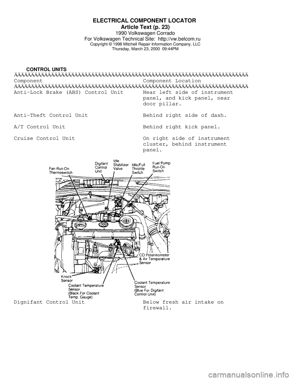
CONTROL UNITSÄÄÄÄÄÄÄÄÄÄÄÄÄÄÄÄÄÄÄÄÄÄÄÄÄÄÄÄÄÄÄÄÄÄÄÄÄÄÄÄÄÄÄÄÄÄÄÄÄÄÄÄÄÄÄÄÄÄÄÄÄÄÄÄÄÄÄÄÄÄComponent Component Location
ÄÄÄÄÄÄÄÄÄÄÄÄÄÄÄÄÄÄÄÄÄÄÄÄÄÄÄÄÄÄÄÄÄÄÄÄÄÄÄÄÄÄÄÄÄÄÄÄÄÄÄÄÄÄÄÄÄÄÄÄÄÄÄÄÄÄÄÄÄÄAnti-Lock Brake (ABS) Control Unit Near left side of instrument
panel, and kick panel, near
door pillar.
Anti-Theft Control Unit Behind right side of dash.
A/T Control Unit Behind right kick panel.
Cruise Control Unit On right side of instrument
cluster, behind instrument
panel.Dignifant Control Unit Below fresh air intake on
firewall.
Page 483 of 906

ELECTRICAL COMPONENT LOCATOR
Article Text (p. 24)
1990 Volkswagen Corrado
For Volkswagen Technical Site: http://vw.belcom.ru
Copyright © 1998 Mitchell Repair Information Company, LLC
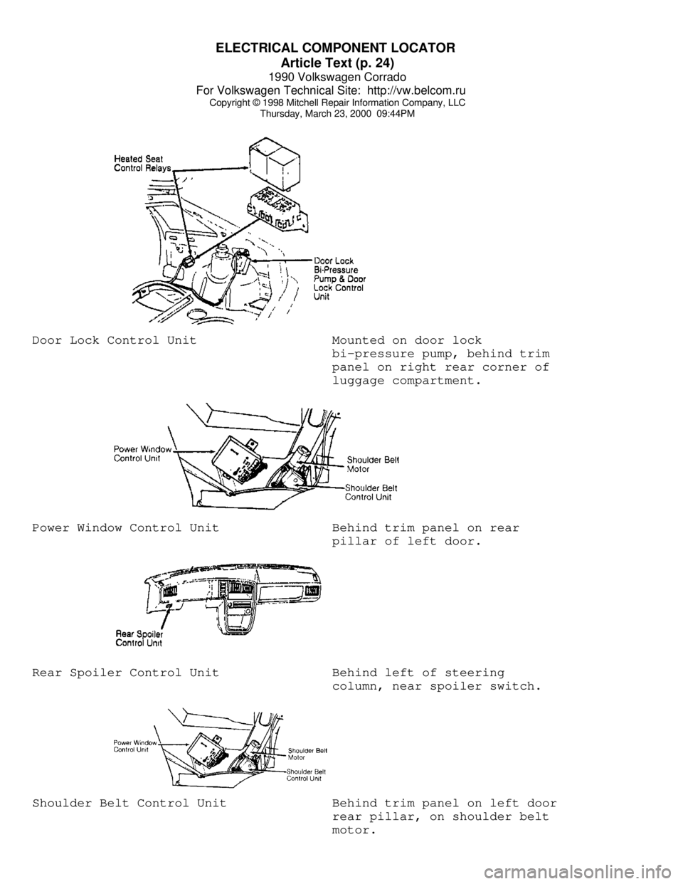
Thursday, March 23, 2000 09:44PMDoor Lock Control Unit Mounted on door lock
bi-pressure pump, behind trim
panel on right rear corner of
luggage compartment.Power Window Control Unit Behind trim panel on rear
pillar of left door.Rear Spoiler Control Unit Behind left of steering
column, near spoiler switch.Shoulder Belt Control Unit Behind trim panel on left door
rear pillar, on shoulder belt
motor.
Page 484 of 906

ELECTRICAL COMPONENT LOCATOR
Article Text (p. 25)
1990 Volkswagen Corrado
For Volkswagen Technical Site: http://vw.belcom.ru
Copyright © 1998 Mitchell Repair Information Company, LLC
Thursday, March 23, 2000 09:44PMÄÄÄÄÄÄÄÄÄÄÄÄÄÄÄÄÄÄÄÄÄÄÄÄÄÄÄÄÄÄÄÄÄÄÄÄÄÄÄÄÄÄÄÄÄÄÄÄÄÄÄÄÄÄÄÄÄÄÄÄÄÄÄÄÄÄÄÄÄÄ MOTORS
ÄÄÄÄÄÄÄÄÄÄÄÄÄÄÄÄÄÄÄÄÄÄÄÄÄÄÄÄÄÄÄÄÄÄÄÄÄÄÄÄÄÄÄÄÄÄÄÄÄÄÄÄÄÄÄÄÄÄÄÄÄÄÄÄÄÄÄÄÄÄComponent Component Location
ÄÄÄÄÄÄÄÄÄÄÄÄÄÄÄÄÄÄÄÄÄÄÄÄÄÄÄÄÄÄÄÄÄÄÄÄÄÄÄÄÄÄÄÄÄÄÄÄÄÄÄÄÄÄÄÄÄÄÄÄÄÄÄÄÄÄÄÄÄÄAnti-Lock Brake (ABS) Pump Motor Below master cylinder.
Blower Motor In bottom of lower air duct
on right side.
Fuel Transfer Pump Motor Mounted in fuel tank.
Rear Spoiler Motor Behind trim panel on rear
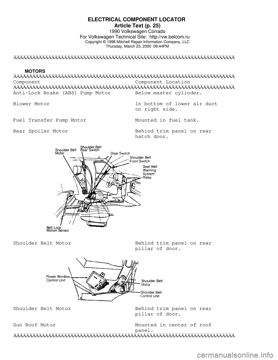
hatch door.Shoulder Belt Motor Behind trim panel on rear
pillar of door.Shoulder Belt Motor Behind trim panel on rear
pillar of door.
Sun Roof Motor Mounted in center of roof
panel.
ÄÄÄÄÄÄÄÄÄÄÄÄÄÄÄÄÄÄÄÄÄÄÄÄÄÄÄÄÄÄÄÄÄÄÄÄÄÄÄÄÄÄÄÄÄÄÄÄÄÄÄÄÄÄÄÄÄÄÄÄÄÄÄÄÄÄÄÄÄÄ
Page 492 of 906

ELECTRICAL COMPONENT LOCATOR
Article Text (p. 33)
1990 Volkswagen Corrado
For Volkswagen Technical Site: http://vw.belcom.ru
Copyright © 1998 Mitchell Repair Information Company, LLC
Thursday, March 23, 2000 09:44PMÄÄÄÄÄÄÄÄÄÄÄÄÄÄÄÄÄÄÄÄÄÄÄÄÄÄÄÄÄÄÄÄÄÄÄÄÄÄÄÄÄÄÄÄÄÄÄÄÄÄÄÄÄÄÄÄÄÄÄÄÄÄÄÄÄÄÄÄÄÄ MISCELLANEOUS
ÄÄÄÄÄÄÄÄÄÄÄÄÄÄÄÄÄÄÄÄÄÄÄÄÄÄÄÄÄÄÄÄÄÄÄÄÄÄÄÄÄÄÄÄÄÄÄÄÄÄÄÄÄÄÄÄÄÄÄÄÄÄÄÄÄÄÄÄÄÄComponent Component Location
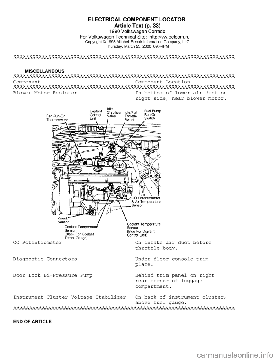
ÄÄÄÄÄÄÄÄÄÄÄÄÄÄÄÄÄÄÄÄÄÄÄÄÄÄÄÄÄÄÄÄÄÄÄÄÄÄÄÄÄÄÄÄÄÄÄÄÄÄÄÄÄÄÄÄÄÄÄÄÄÄÄÄÄÄÄÄÄÄBlower Motor Resistor In bottom of lower air duct on
right side, near blower motor.CO Potentiometer On intake air duct before
throttle body.
Diagnostic Connectors Under floor console trim
plate.
Door Lock Bi-Pressure Pump Behind trim panel on right
rear corner of luggage
compartment.
Instrument Cluster Voltage Stabilizer On back of instrument cluster,
above fuel gauge.
ÄÄÄÄÄÄÄÄÄÄÄÄÄÄÄÄÄÄÄÄÄÄÄÄÄÄÄÄÄÄÄÄÄÄÄÄÄÄÄÄÄÄÄÄÄÄÄÄÄÄÄÄÄÄÄÄÄÄÄÄÄÄÄÄÄÄÄÄÄÄEND OF ARTICLE
Page 671 of 906

MIRRORS - POWER
Article Text (p. 5)
1990 Volkswagen Corrado
For Volkswagen Technical Site: http://vw.belcom.ru
Copyright © 1998 Mitchell Repair Information Company, LLC
Thursday, March 23, 2000 09:49PM
from falling out.
Removal & Installation
1) Disconnect battery ground cable. Lower window. Remove
control knob and boot. Remove door trim, and loosen moisture barrier
in area of rearview mirror control. Remove lock nut. Unplug electrical
connector.
2) Pivot mirror inward, and remove mounting screw. Pivot
mirror outward, and remove second mounting screw. Remove mirror with
base and control. To install, reverse removal procedure.
POWER MIRROR ASSEMBLY (GOLF GL, GTI, JETTA & JETTA GLI)
CAUTION: Always wear protective gloves while handling mirror glass
in case of accidental breakage. Hold glass to prevent it
from falling out.
Removal & Installation
1) Disconnect battery ground cable. Remove mirror glass and
electrical wires. See MIRROR GLASS under REMOVAL & INSTALLATION.
Remove mirror adjustment motor securing screws and motor. Disconnect
electrical wires. Carefully pry mirror adjustment switch from door
panel. Unplug electrical connector.
2) Remove door trim panel and protective cover from door near
mirror wire connectors. Disconnect terminals. To install, connect
adjustment motor wires according to marked color identification.
Reverse removal procedure to complete installation.
POWER MIRROR ASSEMBLY (VANAGON)
CAUTION: Always wear protective gloves while handling mirror glass
in case of accidental breakage. Hold glass to prevent it
from falling out.
Removal & Installation
1) Disconnect battery ground strap. Pry out and disconnect
electric mirror switch from door trim panel. See Fig. 8. Remove door
trim panel, and carefully pull back plastic moisture barrier. Cut tie
wraps securing wiring harness to door. See Fig. 9. Open harness far
enough to expose and label individual wires. Remove labeled wires from
plug connector.
2) Pry off plastic cap at base of mirror bracket, and remove
3 bracket securing screws. See Fig. 10. Remove mirror assembly with
wiring harness. To install, reverse removal procedure, ensuring seal
is positioned for proper fit and wire harness is secured to door frame
with tie wraps. See Fig. 11. Check mirror for proper function.