1990 VOLKSWAGEN CORRADO wheel bolts
[x] Cancel search: wheel boltsPage 756 of 906
SUSPENSION - FRONT
Article Text (p. 4)
1990 Volkswagen Corrado
For Volkswagen Technical Site: http://vw.belcom.ru
Copyright © 1998 Mitchell Repair Information Company, LLC
Thursday, March 23, 2000 09:51PM
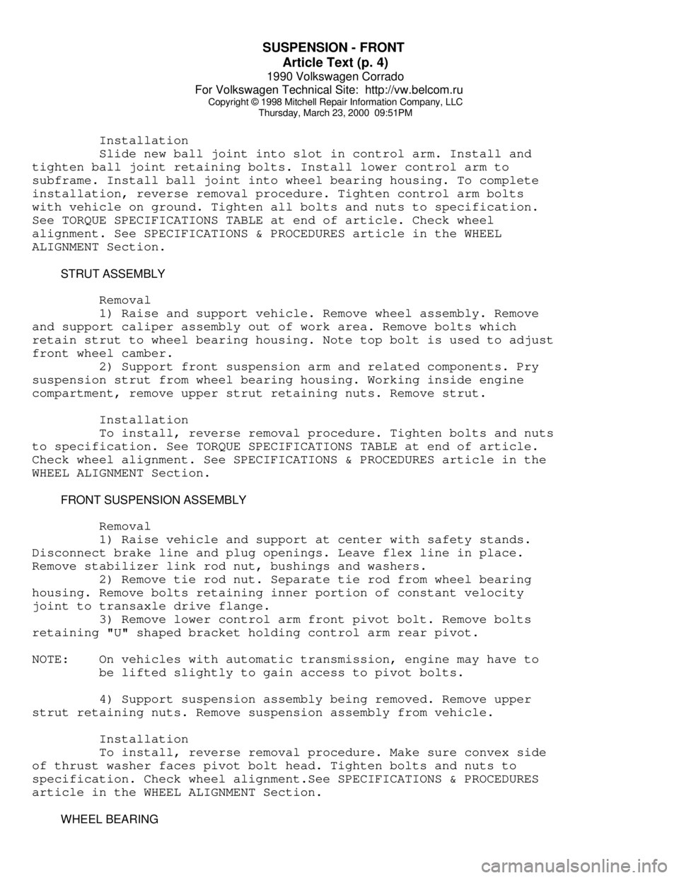
Installation
Slide new ball joint into slot in control arm. Install and
tighten ball joint retaining bolts. Install lower control arm to
subframe. Install ball joint into wheel bearing housing. To complete
installation, reverse removal procedure. Tighten control arm bolts
with vehicle on ground. Tighten all bolts and nuts to specification.
See TORQUE SPECIFICATIONS TABLE at end of article. Check wheel
alignment. See SPECIFICATIONS & PROCEDURES article in the WHEEL
ALIGNMENT Section.
STRUT ASSEMBLY
Removal
1) Raise and support vehicle. Remove wheel assembly. Remove
and support caliper assembly out of work area. Remove bolts which
retain strut to wheel bearing housing. Note top bolt is used to adjust
front wheel camber.
2) Support front suspension arm and related components. Pry
suspension strut from wheel bearing housing. Working inside engine
compartment, remove upper strut retaining nuts. Remove strut.
Installation
To install, reverse removal procedure. Tighten bolts and nuts
to specification. See TORQUE SPECIFICATIONS TABLE at end of article.
Check wheel alignment. See SPECIFICATIONS & PROCEDURES article in the
WHEEL ALIGNMENT Section.
FRONT SUSPENSION ASSEMBLY
Removal
1) Raise vehicle and support at center with safety stands.
Disconnect brake line and plug openings. Leave flex line in place.
Remove stabilizer link rod nut, bushings and washers.
2) Remove tie rod nut. Separate tie rod from wheel bearing
housing. Remove bolts retaining inner portion of constant velocity
joint to transaxle drive flange.
3) Remove lower control arm front pivot bolt. Remove bolts
retaining "U" shaped bracket holding control arm rear pivot.
NOTE: On vehicles with automatic transmission, engine may have to
be lifted slightly to gain access to pivot bolts.
4) Support suspension assembly being removed. Remove upper
strut retaining nuts. Remove suspension assembly from vehicle.
Installation
To install, reverse removal procedure. Make sure convex side
of thrust washer faces pivot bolt head. Tighten bolts and nuts to
specification. Check wheel alignment.See SPECIFICATIONS & PROCEDURES
article in the WHEEL ALIGNMENT Section.
WHEEL BEARING
Page 757 of 906
SUSPENSION - FRONT
Article Text (p. 5)
1990 Volkswagen Corrado
For Volkswagen Technical Site: http://vw.belcom.ru
Copyright © 1998 Mitchell Repair Information Company, LLC
Thursday, March 23, 2000 09:51PM
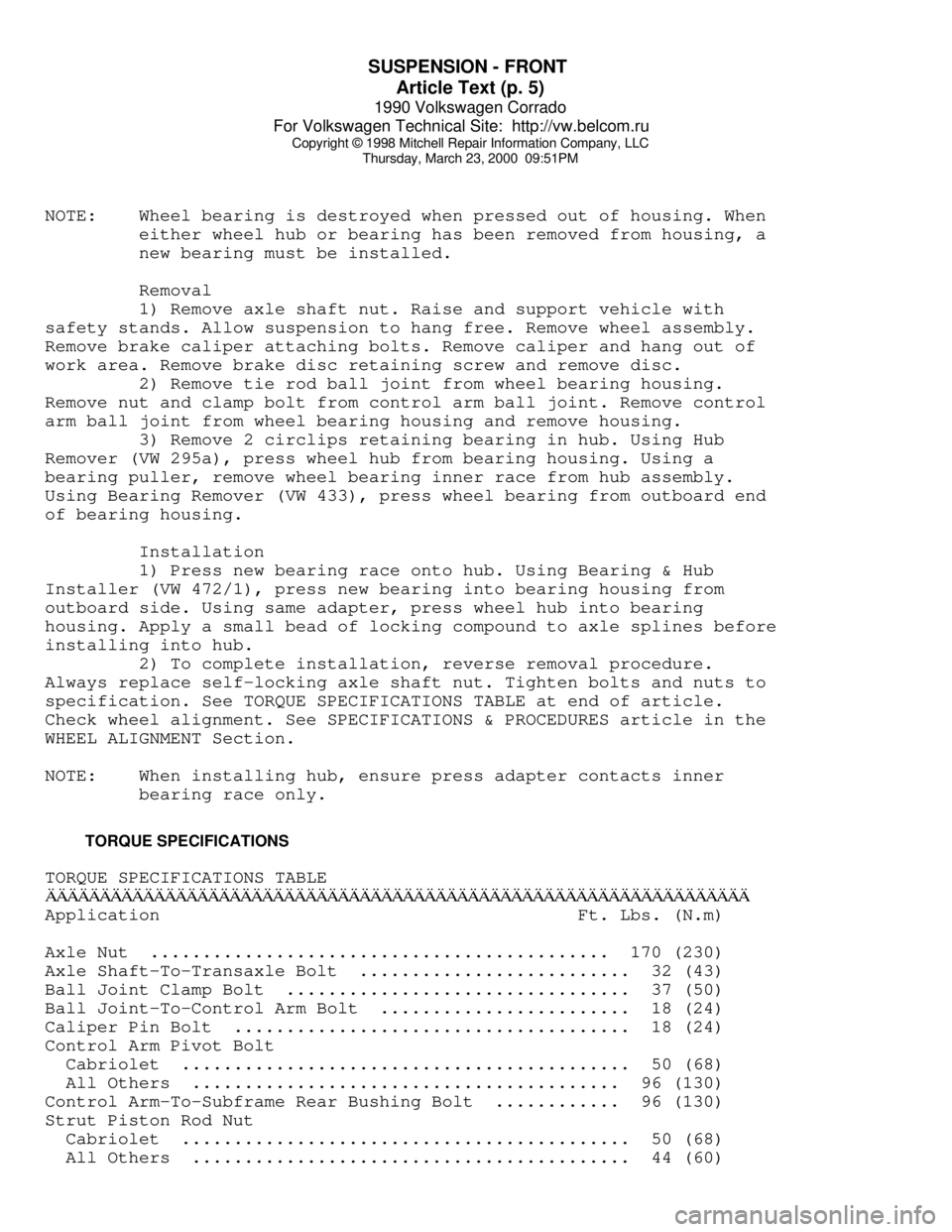
NOTE: Wheel bearing is destroyed when pressed out of housing. When
either wheel hub or bearing has been removed from housing, a
new bearing must be installed.
Removal
1) Remove axle shaft nut. Raise and support vehicle with
safety stands. Allow suspension to hang free. Remove wheel assembly.
Remove brake caliper attaching bolts. Remove caliper and hang out of
work area. Remove brake disc retaining screw and remove disc.
2) Remove tie rod ball joint from wheel bearing housing.
Remove nut and clamp bolt from control arm ball joint. Remove control
arm ball joint from wheel bearing housing and remove housing.
3) Remove 2 circlips retaining bearing in hub. Using Hub
Remover (VW 295a), press wheel hub from bearing housing. Using a
bearing puller, remove wheel bearing inner race from hub assembly.
Using Bearing Remover (VW 433), press wheel bearing from outboard end
of bearing housing.
Installation
1) Press new bearing race onto hub. Using Bearing & Hub
Installer (VW 472/1), press new bearing into bearing housing from
outboard side. Using same adapter, press wheel hub into bearing
housing. Apply a small bead of locking compound to axle splines before
installing into hub.
2) To complete installation, reverse removal procedure.
Always replace self-locking axle shaft nut. Tighten bolts and nuts to
specification. See TORQUE SPECIFICATIONS TABLE at end of article.
Check wheel alignment. See SPECIFICATIONS & PROCEDURES article in the
WHEEL ALIGNMENT Section.
NOTE: When installing hub, ensure press adapter contacts inner
bearing race only.
TORQUE SPECIFICATIONS
TORQUE SPECIFICATIONS TABLEÄÄÄÄÄÄÄÄÄÄÄÄÄÄÄÄÄÄÄÄÄÄÄÄÄÄÄÄÄÄÄÄÄÄÄÄÄÄÄÄÄÄÄÄÄÄÄÄÄÄÄÄÄÄÄÄÄÄÄÄÄÄÄÄÄApplication Ft. Lbs. (N.m)
Axle Nut ............................................ 170 (230)
Axle Shaft-To-Transaxle Bolt .......................... 32 (43)
Ball Joint Clamp Bolt ................................. 37 (50)
Ball Joint-To-Control Arm Bolt ........................ 18 (24)
Caliper Pin Bolt ...................................... 18 (24)
Control Arm Pivot Bolt
Cabriolet ........................................... 50 (68)
All Others ......................................... 96 (130)
Control Arm-To-Subframe Rear Bushing Bolt ............ 96 (130)
Strut Piston Rod Nut
Cabriolet ........................................... 50 (68)
All Others .......................................... 44 (60)
Page 761 of 906
SUSPENSION - REAR
Article Text (p. 3)
1990 Volkswagen Corrado
For Volkswagen Technical Site: http://vw.belcom.ru
Copyright © 1998 Mitchell Repair Information Company, LLC
Thursday, March 23, 2000 09:51PM
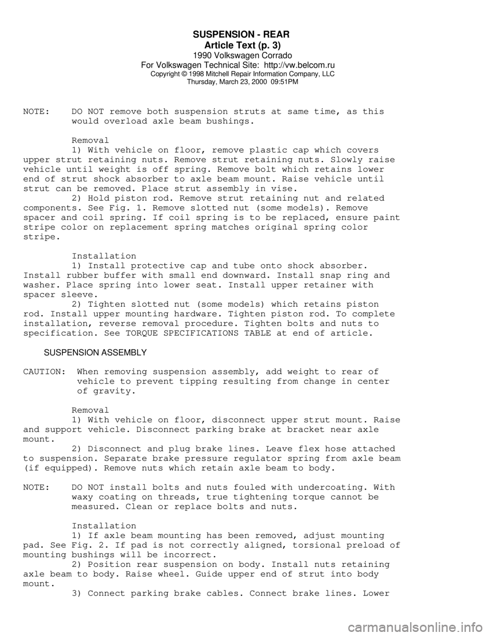
NOTE: DO NOT remove both suspension struts at same time, as this
would overload axle beam bushings.
Removal
1) With vehicle on floor, remove plastic cap which covers
upper strut retaining nuts. Remove strut retaining nuts. Slowly raise
vehicle until weight is off spring. Remove bolt which retains lower
end of strut shock absorber to axle beam mount. Raise vehicle until
strut can be removed. Place strut assembly in vise.
2) Hold piston rod. Remove strut retaining nut and related
components. See Fig. 1. Remove slotted nut (some models). Remove
spacer and coil spring. If coil spring is to be replaced, ensure paint
stripe color on replacement spring matches original spring color
stripe.
Installation
1) Install protective cap and tube onto shock absorber.
Install rubber buffer with small end downward. Install snap ring and
washer. Place spring into lower seat. Install upper retainer with
spacer sleeve.
2) Tighten slotted nut (some models) which retains piston
rod. Install upper mounting hardware. Tighten piston rod. To complete
installation, reverse removal procedure. Tighten bolts and nuts to
specification. See TORQUE SPECIFICATIONS TABLE at end of article.
SUSPENSION ASSEMBLY
CAUTION: When removing suspension assembly, add weight to rear of
vehicle to prevent tipping resulting from change in center
of gravity.
Removal
1) With vehicle on floor, disconnect upper strut mount. Raise
and support vehicle. Disconnect parking brake at bracket near axle
mount.
2) Disconnect and plug brake lines. Leave flex hose attached
to suspension. Separate brake pressure regulator spring from axle beam
(if equipped). Remove nuts which retain axle beam to body.
NOTE: DO NOT install bolts and nuts fouled with undercoating. With
waxy coating on threads, true tightening torque cannot be
measured. Clean or replace bolts and nuts.
Installation
1) If axle beam mounting has been removed, adjust mounting
pad. See Fig. 2. If pad is not correctly aligned, torsional preload of
mounting bushings will be incorrect.
2) Position rear suspension on body. Install nuts retaining
axle beam to body. Raise wheel. Guide upper end of strut into body
mount.
3) Connect parking brake cables. Connect brake lines. Lower
Page 762 of 906
SUSPENSION - REAR
Article Text (p. 4)
1990 Volkswagen Corrado
For Volkswagen Technical Site: http://vw.belcom.ru
Copyright © 1998 Mitchell Repair Information Company, LLC
Thursday, March 23, 2000 09:51PM
vehicle. Tighten upper strut retaining nuts. Tighten all bolts and
nuts to specification. Bleed brake system.
WHEEL BEARING
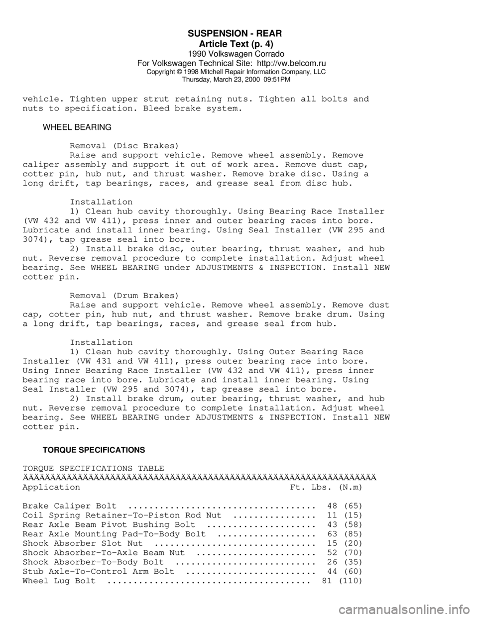
Removal (Disc Brakes)
Raise and support vehicle. Remove wheel assembly. Remove
caliper assembly and support it out of work area. Remove dust cap,
cotter pin, hub nut, and thrust washer. Remove brake disc. Using a
long drift, tap bearings, races, and grease seal from disc hub.
Installation
1) Clean hub cavity thoroughly. Using Bearing Race Installer
(VW 432 and VW 411), press inner and outer bearing races into bore.
Lubricate and install inner bearing. Using Seal Installer (VW 295 and
3074), tap grease seal into bore.
2) Install brake disc, outer bearing, thrust washer, and hub
nut. Reverse removal procedure to complete installation. Adjust wheel
bearing. See WHEEL BEARING under ADJUSTMENTS & INSPECTION. Install NEW
cotter pin.
Removal (Drum Brakes)
Raise and support vehicle. Remove wheel assembly. Remove dust
cap, cotter pin, hub nut, and thrust washer. Remove brake drum. Using
a long drift, tap bearings, races, and grease seal from hub.
Installation
1) Clean hub cavity thoroughly. Using Outer Bearing Race
Installer (VW 431 and VW 411), press outer bearing race into bore.
Using Inner Bearing Race Installer (VW 432 and VW 411), press inner
bearing race into bore. Lubricate and install inner bearing. Using
Seal Installer (VW 295 and 3074), tap grease seal into bore.
2) Install brake drum, outer bearing, thrust washer, and hub
nut. Reverse removal procedure to complete installation. Adjust wheel
bearing. See WHEEL BEARING under ADJUSTMENTS & INSPECTION. Install NEW
cotter pin.
TORQUE SPECIFICATIONS
TORQUE SPECIFICATIONS TABLEÄÄÄÄÄÄÄÄÄÄÄÄÄÄÄÄÄÄÄÄÄÄÄÄÄÄÄÄÄÄÄÄÄÄÄÄÄÄÄÄÄÄÄÄÄÄÄÄÄÄÄÄÄÄÄÄÄÄÄÄÄÄÄÄÄApplication Ft. Lbs. (N.m)
Brake Caliper Bolt .................................... 48 (65)
Coil Spring Retainer-To-Piston Rod Nut ................ 11 (15)
Rear Axle Beam Pivot Bushing Bolt ..................... 43 (58)
Rear Axle Mounting Pad-To-Body Bolt ................... 63 (85)
Shock Absorber Slot Nut ............................... 15 (20)
Shock Absorber-To-Axle Beam Nut ....................... 52 (70)
Shock Absorber-To-Body Bolt ........................... 26 (35)
Stub Axle-To-Control Arm Bolt ......................... 44 (60)
Wheel Lug Bolt ....................................... 81 (110)
Page 764 of 906
TRANSMISSION REMOVAL & INSTALLATION - A/T
Article Text
1990 Volkswagen Corrado
For Volkswagen Technical Site: http://vw.belcom.ru
Copyright © 1998 Mitchell Repair Information Company, LLC
Thursday, March 23, 2000 09:51PM
ARTICLE BEGINNING
1990-91 TRANSMISSION SERVICING
Automatic Transmission Removal & Installation
Cabriolet, Corrado, Fox, Golf GTI, Jetta, Passat
CABRIOLET, GOLF, GTI & JETTA
NOTE: For manual transaxle replacement procedures, see appropriate
CLUTCH article in the CLUTCHES Section.
REMOVAL & INSTALLATION
1) Disconnect battery ground cable. Disconnect speedometer
cable from transaxle. Raise and support vehicle. Remove left front
wheel.
2) Support engine from above. Remove left rear transaxle
mount and support. Remove upper transaxle-to-engine bolts. Remove
upper bolts from front engine/transaxle mount.
3) Remove lower bolts on front mount and remove mount. Remove
protective plate from transaxle. Remove torque converter-to-drive
plate bolts.
4) Disconnect accelerator and selector cables from transaxle.
Place mating marks on drive axle flanges and remove left and right
axle shaft flange bolts.
NOTE: If clearance is needed to remove transaxle, separate ball
joint from left side steering knuckle and move axle shaft
away from transaxle.
5) Remove left rear engine mount. Remove starter. Remove
subframe mounting bolts and allow subframe to hang free. Support
transaxle with jack. Remove lower mounting bolt. Lower transaxle. To
install, reverse removal procedure. Adjust accelerator and selector
cables.
CORRADO & PASSAT
NOTE: For manual transaxle replacement procedures, see appropriate
CLUTCH article in the CLUTCHES Section.
REMOVAL & INSTALLATION
1) Disconnect battery ground cable. Remove air ducts to brake
caliper and engine air intake. Disconnect speedometer cable from
transaxle. Remove upper transaxle-to-engine bolts.
2) Disconnect and plug transaxle cooler lines. Support engine
from above. Remove starter. Disconnect accelerator and selector cables
from transaxle. Remove left transaxle mount and support.
3) Remove electrical wiring from transaxle. Remove lower
Page 788 of 906
TROUBLE SHOOTING - BASIC PROCEDURES
Article Text (p. 12)
1990 Volkswagen Corrado
For Volkswagen Technical Site: http://vw.belcom.ru
Copyright © 1998 Mitchell Repair Information Company, LLC
Thursday, March 23, 2000 09:52PM
Incorrect transmission Realign transmission
alignment
Worn pressure plate, disc Replace damaged
or flywheel components
Broken or weak pressure Replace pressure
springs plate
Sticking clutch pedal Lubricate clutch pedal
& linkage
Incorrect clutch disc Replace clutch disc
facing
Engine loose in chassis Tighten all mounting
boltsÄÄÄÄÄÄÄÄÄÄÄÄÄÄÄÄÄÄÄÄÄÄÄÄÄÄÄÄÄÄÄÄÄÄÄÄÄÄÄÄÄÄÄÄÄÄÄÄÄÄÄÄÄÄÄÄÄÄÄÄÄÄÄÄÄÄÄÄÄÄFailure to Oil or grease on clutch Clean or replace clutch
Release facings clutch disc
Incorrect release lever or See CLUTCH article
pedal adjustment
Worn or broken clutch Replace clutch disc
facings
Bent clutch disc or Replace damaged
pressure plate components
Clutch disc hub binding on Clean or replace clutch
input shaft disc and/or input shaft
Binding pilot bearing Replace pilot bearing
Sticking release bearing Replace release bearing
sleeve and/or sleeve
Binding clutch cable See CLUTCH article
Defective clutch master Replace master cylinder
Defective clutch slave Replace slave cylinder
Air in hydraulic system Bleed hydraulic system
ÄÄÄÄÄÄÄÄÄÄÄÄÄÄÄÄÄÄÄÄÄÄÄÄÄÄÄÄÄÄÄÄÄÄÄÄÄÄÄÄÄÄÄÄÄÄÄÄÄÄÄÄÄÄÄÄÄÄÄÄÄÄÄÄÄÄÄÄÄÄRattling Weak or broken release Replace spring and
lever spring check alignment
Damaged pressure plate Replace pressure plate
Page 797 of 906
TROUBLE SHOOTING - BASIC PROCEDURES
Article Text (p. 21)
1990 Volkswagen Corrado
For Volkswagen Technical Site: http://vw.belcom.ru
Copyright © 1998 Mitchell Repair Information Company, LLC
Thursday, March 23, 2000 09:52PM
broken loose, the carrier and housing must be cleaned to remove
particles that could cause damage.
KNOCK
This is very similar to a chuckle, though it may be louder,
and occur on acceleration or deceleration. Knock can be caused by a
gear tooth that is damaged on the drive side of the ring and pinion
gears. Ring gear bolts that are hitting the carrier casting can cause
knock. Knock can also be due to excessive end play in the axle shafts.
CLUNK
Clunk is a metallic noise heard when an automatic
transmission is engaged in Reverse or Drive, or when throttle is
applied or released. It is caused by backlash somewhere in the
driveline, but not necessarily in the axle. To determine whether
driveline clunk is caused by the axle, check the total axle backlash
as follows:
1) Raise vehicle on a frame or twinpost hoist so that drive
wheels are free. Clamp a bar between axle companion flange and a part
of the frame or body so that flange cannot move.
2) On conventional drive axles, lock the left wheel to keep
it from turning. On all models, turn the right wheel slowly until it
is felt to be in Drive condition. Hold a chalk marker on side of tire
about 12" from center of wheel. Turn wheel in the opposite direction
until it is again felt to be in Drive condition.
3) Measure the length of the chalk mark, which is the total
axle backlash. If backlash is one inch or less, drive axle is not the
source of clunk noise.
BEARING WHINE
Bearing whine is a high-pitched sound similar to a whistle.
It is usually caused by malfunctioning pinion bearings. Pinion
bearings operate at drive shaft speed. Roller wheel bearings may whine
in a similar manner if they run completely dry of lubricant. Bearing
noise will occur at all driving speeds. This distinguishes it from
gear whine, which usually comes and goes as speed changes.
BEARING RUMBLE
Bearing rumble sounds like marbles being tumbled. It is
usually caused by a malfunctioning wheel bearing. The lower pitch is
because the wheel bearing turns at only about 1/3 of drive shaft
speed.
CHATTER ON TURNS
This is a condition where the entire front or rear of vehicle
vibrates when vehicle is moving. The vibration is plainly felt as well
Page 807 of 906
TROUBLE SHOOTING - BASIC PROCEDURES
Article Text (p. 31)
1990 Volkswagen Corrado
For Volkswagen Technical Site: http://vw.belcom.ru
Copyright © 1998 Mitchell Repair Information Company, LLC
Thursday, March 23, 2000 09:52PMÄÄÄÄÄÄÄÄÄÄÄÄÄÄÄÄÄÄÄÄÄÄÄÄÄÄÄÄÄÄÄÄÄÄÄÄÄÄÄÄÄÄÄÄÄÄÄÄÄÄÄÄÄÄÄÄÄÄÄÄÄÄÄÄÄÄÄÄÄÄNoisy Main Inadequate oil supply Check oil delivery to
Bearings main bearings
Excessive main bearing Replace main bearings,
clearance See ENGINES
Excessive crankshaft end Replace crankshaft, See
play ENGINES
Loose flywheel or torque Tighten attaching bolts
converter
Loose or damaged vibration Tighten or replace
damper vibration damper
Crankshaft journals Re-grind crankshaft
out-of-round journals
Excessive belt tension Loosen belt tension
ÄÄÄÄÄÄÄÄÄÄÄÄÄÄÄÄÄÄÄÄÄÄÄÄÄÄÄÄÄÄÄÄÄÄÄÄÄÄÄÄÄÄÄÄÄÄÄÄÄÄÄÄÄÄÄÄÄÄÄÄÄÄÄÄÄÄÄÄÄÄNoisy Connecting Excessive bearing clearance Replace bearing, See
Rods or missing bearing ENGINES
Crankshaft rod journal Re-grind crankshaft
out-of-round journal
Misaligned connecting rod Remove rod or cap and
or cap realign
Incorrectly tightened rod Remove and re-tighten
bolts rod bolts
ÄÄÄÄÄÄÄÄÄÄÄÄÄÄÄÄÄÄÄÄÄÄÄÄÄÄÄÄÄÄÄÄÄÄÄÄÄÄÄÄÄÄÄÄÄÄÄÄÄÄÄÄÄÄÄÄÄÄÄÄÄÄÄÄÄÄÄÄÄÄNoisy Pistons Excessive piston-to-bore Install larger pistons,
and Rings clearance See ENGINES
Bore tapered or out-of-round Rebore block
Piston ring broken Replace piston rings,
See ENGINES
Piston pin loose or seized Replace piston pin, See
ENGINES
Connecting rods misaligned Realign connecting rods
Ring side clearance too Replace with larger or
loose or tight smaller rings
Carbon build-up on piston Remove carbon
ÄÄÄÄÄÄÄÄÄÄÄÄÄÄÄÄÄÄÄÄÄÄÄÄÄÄÄÄÄÄÄÄÄÄÄÄÄÄÄÄÄÄÄÄÄÄÄÄÄÄÄÄÄÄÄÄÄÄÄÄÄÄÄÄÄÄÄÄÄÄNoisy Valve Worn or bent push rods Replace push rods, See
Train ENGINES
Worn rocker arms or bridged Replace push rods, See
pivots ENGINES
Dirt or chips in valve Remove lifters and
lifters remove dirt/chips
Excessive valve lifter Replace valve lifters,
leak-down See ENGINES
Valve lifter face worn Replace valve lifters,
See ENGINES
Broken or cocked valve replace or reposition
springs springs
Too much valve stem-to-guide Replace valve guides,
clearance See ENGINES
Valve bent Replace valve, See
ENGINES