1990 VOLKSWAGEN CORRADO check oil
[x] Cancel search: check oilPage 590 of 906

I - SYSTEM/COMPONENT TESTS
Article Text (p. 3)
1990 Volkswagen Corrado
For Volkswagen Technical Site: http://vw.belcom.ru
Copyright © 1998 Mitchell Repair Information Company, LLC
Thursday, March 23, 2000 09:46PM
circuits to ECU. The ECU engine ground is near ignition distributor.
Remove ECU connector. Check resistance to ground on terminal No. 35.
Resistance should be zero ohms. If resistance is not zero ohms, repair
open or short in wiring.
POWER CIRCUITS
Turn ignition off. Disconnect ECU connector. Using a
voltmeter, check terminals No. 12, 14, 19 and 34 for battery voltage.
If battery voltage is not present. Check fuses No. 15, 18 and 24. If
fuses are okay, check for open in wiring between ECU and fuse box. See
L - WIRING DIAGRAMS for terminal identification and wire colors.
ENGINE SENSORS & SWITCHES
AIRFLOW SENSOR (FOX & JETTA GLI)
1) Start engine to pressurized fuel system. Turn engine off
and remove intake boot from top of airflow sensor. Disconnect coil
secondary wire from coil and jumper to ground.
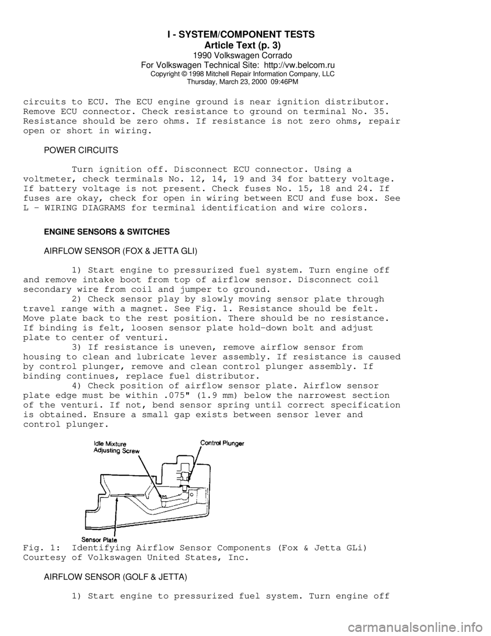
2) Check sensor play by slowly moving sensor plate through
travel range with a magnet. See Fig. 1. Resistance should be felt.
Move plate back to the rest position. There should be no resistance.
If binding is felt, loosen sensor plate hold-down bolt and adjust
plate to center of venturi.
3) If resistance is uneven, remove airflow sensor from
housing to clean and lubricate lever assembly. If resistance is caused
by control plunger, remove and clean control plunger assembly. If
binding continues, replace fuel distributor.
4) Check position of airflow sensor plate. Airflow sensor
plate edge must be within .075" (1.9 mm) below the narrowest section
of the venturi. If not, bend sensor spring until correct specification
is obtained. Ensure a small gap exists between sensor lever and
control plunger.Fig. 1: Identifying Airflow Sensor Components (Fox & Jetta GLi)
Courtesy of Volkswagen United States, Inc.
AIRFLOW SENSOR (GOLF & JETTA)
1) Start engine to pressurized fuel system. Turn engine off
Page 597 of 906

I - SYSTEM/COMPONENT TESTS
Article Text (p. 10)
1990 Volkswagen Corrado
For Volkswagen Technical Site: http://vw.belcom.ru
Copyright © 1998 Mitchell Repair Information Company, LLC
Thursday, March 23, 2000 09:46PM
FUEL CONTROL
COLD START VALVE (ALL MODELS EXCEPT VANAGON)
1) Engine temperature must be below 85øF (30øC). Disconnect
cold start valve attaching screws and remove valve with harness
connector and fuel line attached.
2) Remove ignition coil secondary wire and jumper to ground.
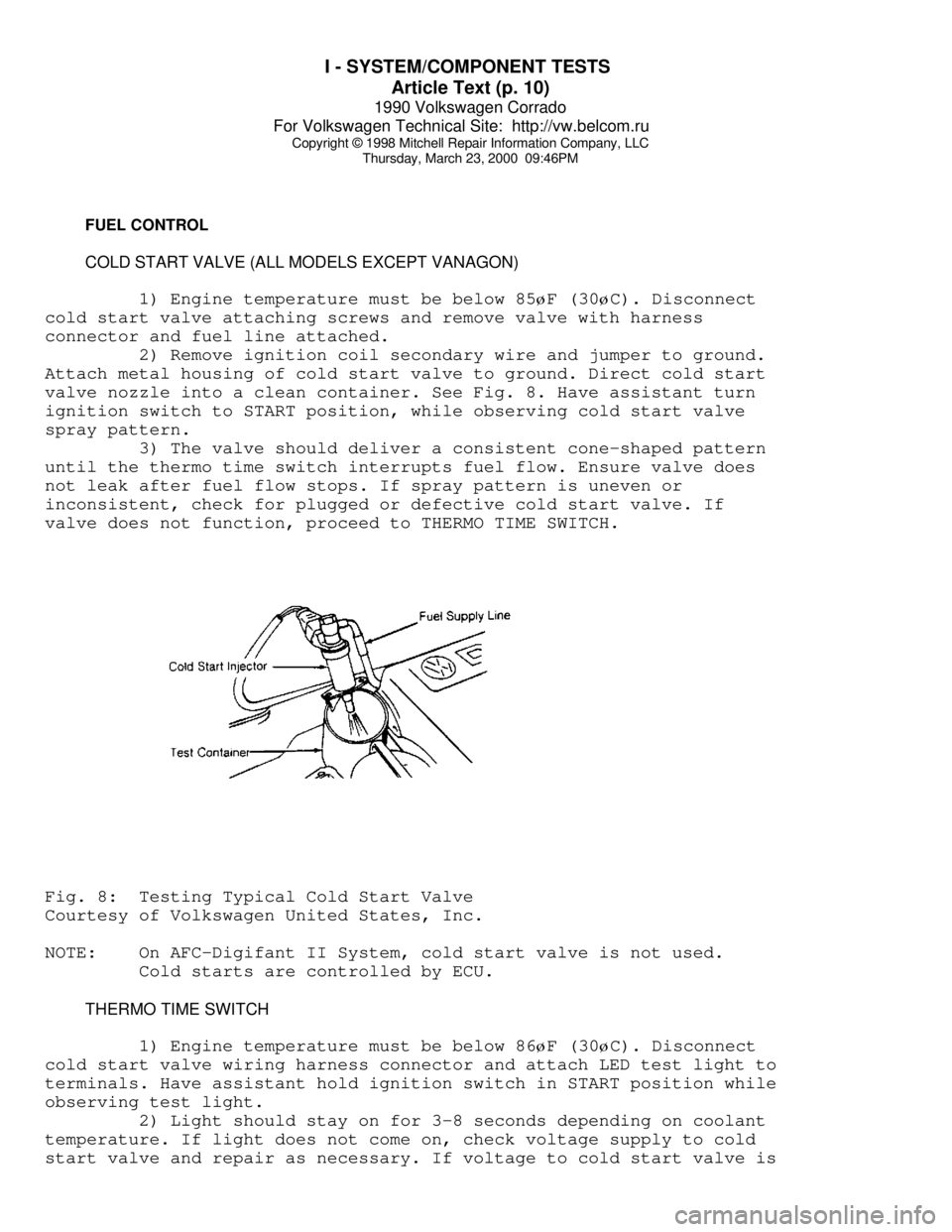
Attach metal housing of cold start valve to ground. Direct cold start
valve nozzle into a clean container. See Fig. 8. Have assistant turn
ignition switch to START position, while observing cold start valve
spray pattern.
3) The valve should deliver a consistent cone-shaped pattern
until the thermo time switch interrupts fuel flow. Ensure valve does
not leak after fuel flow stops. If spray pattern is uneven or
inconsistent, check for plugged or defective cold start valve. If
valve does not function, proceed to THERMO TIME SWITCH.Fig. 8: Testing Typical Cold Start Valve
Courtesy of Volkswagen United States, Inc.
NOTE: On AFC-Digifant II System, cold start valve is not used.
Cold starts are controlled by ECU.
THERMO TIME SWITCH
1) Engine temperature must be below 86
øF (30øC). Disconnect
cold start valve wiring harness connector and attach LED test light to
terminals. Have assistant hold ignition switch in START position while
observing test light.
2) Light should stay on for 3-8 seconds depending on coolant
temperature. If light does not come on, check voltage supply to cold
start valve and repair as necessary. If voltage to cold start valve is
Page 598 of 906

I - SYSTEM/COMPONENT TESTS
Article Text (p. 11)
1990 Volkswagen Corrado
For Volkswagen Technical Site: http://vw.belcom.ru
Copyright © 1998 Mitchell Repair Information Company, LLC
Thursday, March 23, 2000 09:46PM
okay, check ground circuit through thermo time switch. Replace thermo
time switch if contact to ground cannot be made.
IDLE CONTROL SYSTEM
NOTE: Knock control is integral in AFC-Digifant II ECU.
KNOCK SENSOR CONTROL UNIT (ALL MODELS EXCEPT VANAGON)
1) Check ignition coil and Hall Effect sender before checking
knock sensor control unit. Remove knock sensor control unit harness
connector. Turn ignition on. Using a voltmeter, check for battery
voltage between terminals No. 3 and No. 5 and terminals No. 6 and No.
3 of knock sensor control unit. Open throttle valve. Voltage should
drop to zero volts.
2) If voltage does not drop to zero volts, check throttle
valve switch (full throttle). Check voltage between terminals No. 8
and No. 3, while fully opening throttle valve. If battery voltage was
not present when throttle fully open, replace throttle valve switch.
See Fig. 13.
3) Remove Hall Effect sender connector and connect voltmeter
to outside terminals. Turn ignition on. There should be 5 volts
present. Turn ignition off. Connect voltmeter between terminals No. 1
(negative) and No. 15 (positive) of ignition coil. Turn ignition on
and touch center terminal of Hall Effect sender briefly to ground.
Voltage should jump momentarily to approximately 2 volts. If voltage
does not jump, replace knock sensor control unit.
KNOCK SENSOR(S)
Before replacing knock sensor, check knock sensor torque and
resistance. Remove knock sensor connector and check resistance between
terminals No. 13 and No. 14. See KNOCK SENSOR TORQUE & RESISTANCE
SPECIFICATION table. If resistance is incorrect, replace knock sensor.
NOTE: Knock sensor mounting bolt torque must be exact. DO NOT use
washers when mounting knock sensor.
KNOCK SENSOR RESISTANCE & TORQUE SPECIFICATIONÄÄÄÄÄÄÄÄÄÄÄÄÄÄÄÄÄÄÄÄÄÄÄÄÄÄÄÄÄÄÄÄÄÄÄÄÄÄÄÄÄÄÄÄÄÄÄÄÄÄÄÄÄÄÄÄÄÄÄÄÄÄÄÄÄÄÄÄÄÄApplication Resistance Ft. Lbs (N.m)
Type I ...................... 300,000 ................ 7-9 (10-12)
Type II .................... Infinite .............. 15-18 (20-25)
ÄÄÄÄÄÄÄÄÄÄÄÄÄÄÄÄÄÄÄÄÄÄÄÄÄÄÄÄÄÄÄÄÄÄÄÄÄÄÄÄÄÄÄÄÄÄÄÄÄÄÄÄÄÄÄÄÄÄÄÄÄÄÄÄÄÄÄÄÄÄ IDLE STABILIZATION SYSTEM (VANAGON)
1) Attach Test Meter (VW 1315/2) and Adapter (US 1119) to
idle stabilization valve. Set meter to milliampere scale. Start
engine. Observe test meter while turning A/C control switch to ON
position. If milliampere reading increases, system is okay.
Page 603 of 906

INSTRUMENT PANEL
Article Text
1990 Volkswagen Corrado
For Volkswagen Technical Site: http://vw.belcom.ru
Copyright © 1998 Mitchell Repair Information Company, LLC
Thursday, March 23, 2000 09:46PM
ARTICLE BEGINNING
1989-90 ACCESSORIES & EQUIPMENT
Volkswagen Instrument Panels
Cabriolet, Fox, Golt, GTI, Jetta, Jetta GLI, Vanagon
DESCRIPTION & OPERATION
Instrument cluster for most models includes speedometer, fuel
gauge and temperature gauge. Optional instruments include clock,
tachometer, voltmeter and oil temperature gauge.
Printed circuit provides voltage to gauges. A voltage
regulator attached to the printed circuit controls voltage to fuel and
temperature gauges. Light Emitting Diodes (LEDs) are used for most
warning lights. To replace diodes, pull from printed circuit sockets.
NOTE: Volkswagen Tester (1301) is required for resistance tests.
Tester settings are numerical. Settings do not indicate
resistance in ohms. Manufacturer does not supply resistance
value in ohms.
TESTING
FUEL & TEMPERATURE GAUGE
1) Disconnect wire from fuel tank or temperature sending
unit. Connect VW tester between wire and ground. Turn ignition on and
allow 2 minutes for gauge reading to stabilize. Use FUEL GAUGE TESTING
or TEMPERATURE GAUGE TESTING table to compare gauge reading. Gauge
should be within one pointer width of specification.
2) If gauge needle does not move, check continuity between
sender wire and gauge. If needle moves, but does not match
specifications, replace gauge. If gauge works correctly with tester,
but not sending unit, replace sending unit.
FUEL GAUGE TESTINGÄÄÄÄÄÄÄÄÄÄÄÄÄÄÄÄÄÄÄÄÄÄÄÄÄÄÄÄÄÄÄÄÄÄÄÄÄÄÄÄÄÄÄÄÄÄÄÄÄÄÄÄÄÄÄApplication Dial Setting Indicator
Cabriolet & Fox .......... 55 ................ Full
560 ................Empty
Golf, GTI, Jetta
& Jetta GLI .............. 52 ................ Full
550 ................Empty
Vanagon .................. 50 ................ Full
320 ................Empty
ÄÄÄÄÄÄÄÄÄÄÄÄÄÄÄÄÄÄÄÄÄÄÄÄÄÄÄÄÄÄÄÄÄÄÄÄÄÄÄÄÄÄÄÄÄÄÄÄÄÄÄÄÄÄÄTEMPERATURE GAUGE TESTING
ÄÄÄÄÄÄÄÄÄÄÄÄÄÄÄÄÄÄÄÄÄÄÄÄÄÄÄÄÄÄÄÄÄÄÄÄÄÄÄÄÄÄÄÄÄÄÄÄÄÄÄÄÄÄÄ
Page 607 of 906

INTERFERENCE VERIFICATION CHECK FOR OHC ENGINE
Article Text
1990 Volkswagen Corrado
For Volkswagen Technical Site: http://vw.belcom.ru
Copyright © 1998 Mitchell Repair Information Company, LLC
Thursday, March 23, 2000 09:46PM
ARTICLE BEGINNING
Maintenance & Service Information
1974-96 Volkswagen - Timing Belt Information
Cabrio, Cabriolet, Corrado, Dasher, Eurovan (Canadian), Fox,
Golf, Golf (Canadian), GTI, GTI (Canadian), Jetta, Jetta GLI,
Passat, Passat (Canadian), Pickup, Quantum, Rabbit, Scirocco,
Scirocco (Canadian), Transporter (Canadian), Vanagon
TIMING BELT INTERFERENCE VERIFICATION INFORMATION
TIMING BELT INTERFERENCE CAUTION
NOTE: CAMSHAFT DRIVE BELTS OR TIMING BELTS - The condition of
camshaft drive belts should always be checked on vehicles
which have more than 50,000 miles. Although some
manufacturers do not recommend replacement at a specified
mileage, others require it at 60,000-100,000 miles. A
camshaft drive belt failure may cause extensive damage to
internal engine components on most engines, although some
designs do not allow piston-to-valve contact. These designs
are often called "Free Wheeling". Many manufacturers changed
their maintenance and warranty schedules in the mid-1980's to
reflect timing belt inspection and/or replacement at
50,000-60,000 miles. Most service interval schedules shown in
this section reflect these changes. Belts or components
should be inspected and replaced if any of the following
conditions exist:
* Crack Or Tears In Belt Surface
* Missing, Damaged, Cracked Or Rounded Teeth
* Oil Contamination
* Damaged Or Faulty Tensioners
* Incorrect Tension Adjustment
TIMING BELT INTERFERENCE CHECK MENU
TIMING BELT INTERFERENCE VERIF. TABLE - PASSENGER CARS (1)ÄÄÄÄÄÄÄÄÄÄÄÄÄÄÄÄÄÄÄÄÄÄÄÄÄÄÄÄÄÄÄÄÄÄÄÄÄÄÄÄÄÄÄÄÄÄÄÄÄÄÄÄÄÄÄÄÄÄÄÄ Replacement Interval
Application Engine (Miles)
Cabrio
1995-96 .......... 2.0L 4-Cyl. ............ (3) 60,000
Cabriolet
1985-89 ....... 1.8L 4-Cyl. (DOHC) ........ (3) 60,000
1.8L 4-Cyl. (SOHC) ........ (3) 60,000
1990-93 .......... 1.8L 4-Cyl. ............ (3) 60,000
Corrado
1990-92 .......... 1.8L 4-Cyl. ............ (3) 60,000
Dasher
Page 638 of 906

MAINTENANCE INFORMATION
Article Text (p. 3)
1990 Volkswagen Corrado
For Volkswagen Technical Site: http://vw.belcom.ru
Copyright © 1998 Mitchell Repair Information Company, LLC
Thursday, March 23, 2000 09:48PM
Severe Service (Unique Driving Conditions)
* Short Trips In Freezing Temperatures
* Towing Or Heavily Loaded
* Severe Dust Conditions
* Hot Weather, Stop-And-Go Driving
* Extensive Idling
CAMSHAFT TIMING BELT
CAUTION: Failure to replace a faulty camshaft timing belt may result
in serious engine damage.
The condition of camshaft drive belts should always be
checked on vehicles which have more than 50,000 miles. Although some
manufacturers do not recommend belt replacement at a specified
mileage, others require it at 60,000-100,000 miles. A camshaft drive
belt failure may cause extensive damage to internal engine components
on most engines, although some designs do not allow piston-to-valve
contact. These designs are often called "Free Wheeling".
Many manufacturers changed their maintenance and warranty
schedules in the mid-1980's to reflect timing belt inspection and/or
replacement at 50,000-60,000 miles. Most service interval schedules in
this manual reflect these changes.
Belts or components should be inspected and replaced if any
of the following conditions exist:
* Cracks Or Tears In Belt Surface
* Missing, Damaged, Cracked Or Rounded Teeth
* Oil Contamination
* Damaged Or Faulty Tensioners
* Incorrect Tension Adjustment
Inspect camshaft timing belt condition every 20,000 miles.
Replace belt as necessary.
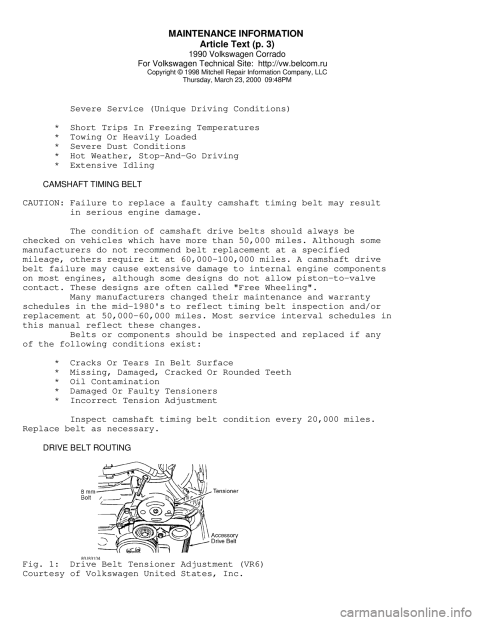
DRIVE BELT ROUTINGFig. 1: Drive Belt Tensioner Adjustment (VR6)
Courtesy of Volkswagen United States, Inc.
Page 674 of 906

N - REMOVE/INSTALL/OVERHAUL
Article Text
1990 Volkswagen Corrado
For Volkswagen Technical Site: http://vw.belcom.ru
Copyright © 1998 Mitchell Repair Information Company, LLC
Thursday, March 23, 2000 09:49PM
ARTICLE BEGINNING
1990 ENGINE PERFORMANCE
Removal, Overhaul & Installation
Volkswagen; Cabriolet, Corrado, Fox, Golf GL/GTI,
Jetta, Vanagon
INTRODUCTION
Removal, overhaul and installation procedures are covered in
this article. If component removal and installation is primarily an
unbolt and bolt-on procedure, only a torque specification may be
furnished. See TORQUE SPECIFICATIONS at the end of this article.
REMOVAL & INSTALLATION
DISTRIBUTOR (DIGIFANT)
Removal (AFC-Digifant II)
Turn engine crankshaft to TDC. Remove distributor cap. Rotor
should point to No. 1 cylinder mark on edge of distributor housing.
Index mark the distributor housing to the crankcase relation. Remove
distributor hold-down clamp and bolt. Remove distributor assembly.
Installation
Align rotor with No. 1 cylinder mark on edge of distributor
housing. Install distributor and align housing to index mark made on
crankcase. Install distributor hold-down clamp and bolt. Install
distributor cap. Check timing. Tighten hold-down bolt to
specification. See TORQUE SPECIFICATIONS.
DISTRIBUTOR (CIS SYSTEMS)
Removal (CIS-E & CIS-E Motronic)
1) Turn engine crankshaft to TDC. Marking on vibration
dampener pulley must align with drive belt guard pointer. Marking on
cam shaft gear sprocket must align with cylinder head cover.
2) Remove distributor cap and mark position of rotor. Rotor
should be pointing to No. 1 cylinder in distributor firing sequence.
Mark position of distributor housing for installation reference.
Remove distributor hold-down clamp and bolt. Remove distributor
assembly, noting position of rotor when distributor shaft gear is
disengaged from driving gear.
Installation
1) Align oil pump drive pinion lug parallel to crankshaft.
Set rotor pointing toward mark made when distributor was disengaged
from drive gear.
2) Install distributor. Rotor should now point to mark made
for No. 1 cylinder in distributor firing sequence. Align mark for
Page 692 of 906

SCHEDULED SERVICES
Article Text (p. 9)
1990 Volkswagen Corrado
For Volkswagen Technical Site: http://vw.belcom.ru
Copyright © 1998 Mitchell Repair Information Company, LLC
Thursday, March 23, 2000 09:49PM
CAMSHAFT TIMING BELT REPLACEMENT INFORMATION
CAUTION: Failure to replace a faulty camshaft timing belt may result
in serious engine damage.
The condition of camshaft drive belts should always be
checked on vehicles which have more than 50,000 miles. Although some
manufacturers do not recommend belt replacement at a specified
mileage, others require it at 60,000-100,000 miles. A camshaft drive
belt failure may cause extensive damage to internal engine components
on most engines, although some designs do not allow piston-to-valve
contact. These designs are often called "Free Wheeling".
Many manufacturers changed their maintenance and warranty
schedules in the mid-1980's to reflect timing belt inspection and/or
replacement at 50,000-60,000 miles. Most service interval schedules in
this manual reflect these changes.
Belts or components should be inspected and replaced if any
of the following conditions exist:
* Cracks Or Tears In Belt Surface
* Missing, Damaged, Cracked Or Rounded Teeth
* Oil Contamination
* Damaged Or Faulty Tensioners
* Incorrect Tension Adjustment
Inspect camshaft timing belt condition every 20,000 miles.
Replace belt as necessary.
SEVERE & NORMAL SERVICE DEFINITIONS
NOTE: Use the Severe Service schedule if the vehicle to be serviced
is operated under ANY (one or more) of these conditions:
Service is recommended at mileage intervals based on vehicle
operation. Service schedules are based on the following primary
operating conditions:
Normal Service
* Driven More Than 10 Miles Daily
* No Operating Conditions From Severe Service Schedule
Severe Service (Unique Driving Conditions)
* Short Trips In Freezing Temperatures
* Towing Or Heavily Loaded
* Severe Dust Conditions
* Hot Weather, Stop-And-Go Driving
* Extensive Idling
SEVERE SERVICE REQUIREMENTS (PERFORM W/SERVICE SCHEDULES)