1990 VOLKSWAGEN CORRADO instrument cluster
[x] Cancel search: instrument clusterPage 383 of 906

ABBREVIATIONS
Article Text (p. 6)
1990 Volkswagen Corrado
For Volkswagen Technical Site: http://vw.belcom.ru
Copyright © 1998 Mitchell Repair Information Company, LLC
Thursday, March 23, 2000 09:42PMÚÄÄÄÄÄÄÄÄÄÄÄÄÄÄÄÄÄÂÄÄÄÄÄÄÄÄÄÄÄÄÄÄÄÄÄÄÄÄÄÄÄÄÄÄÄÄÄÄÄÄÄÄÄÄÄÄÄÄÄÄÄÄÄÄÄÄÄÄ¿
³ABBREVIATION
³DEFINITION ³
ÃÄÄÄÄÄÄÄÄÄÄÄÄÄÄÄÄÄÅÄÄÄÄÄÄÄÄÄÄÄÄÄÄÄÄÄÄÄÄÄÄÄÄÄÄÄÄÄÄÄÄÄÄÄÄÄÄÄÄÄÄÄÄÄÄÄÄÄÄ´
³H/D
³Heavy Duty ³
³HAC
³High Altitude Compensation ³
³HC
³Hydrocarbons ³
³HEDF
³High Speed Electro Drive Fan relay or circuit ³
³HEGO
³Heated Exhaust Gas Oxygen Sensor ³
³HEGOG
³HEGO Ground circuit ³
³HEI
³High Energy Ignition ³
³HLDT
³Headlight ³
³HO
³High Output ³
³HP
³High Performance ³
³HSC
³High Swirl Combustion ³
³HSO
³High Specific Output ³
³HTR
³Heater ³
³HVAC
³Heating ³
³Headlt.
³Headlight ³
³Hg
³Mercury ³
³Hgt.
³Height ³
³Htr.
³Heater ³
³Hz
³Hertz (Cycles Per Second) ³
ÀÄÄÄÄÄÄÄÄÄÄÄÄÄÄÄÄÄÁÄÄÄÄÄÄÄÄÄÄÄÄÄÄÄÄÄÄÄÄÄÄÄÄÄÄÄÄÄÄÄÄÄÄÄÄÄÄÄÄÄÄÄÄÄÄÄÄÄÄÙ "I" ABBREVIATION TABLE
"I" ABBREVIATION TABLE
ÚÄÄÄÄÄÄÄÄÄÄÄÄÄÄÄÄÄÂÄÄÄÄÄÄÄÄÄÄÄÄÄÄÄÄÄÄÄÄÄÄÄÄÄÄÄÄÄÄÄÄÄÄÄÄÄÄÄÄÄÄÄÄÄÄÄÄÄÄ¿
³ABBREVIATION
³DEFINITION ³
ÃÄÄÄÄÄÄÄÄÄÄÄÄÄÄÄÄÄÅÄÄÄÄÄÄÄÄÄÄÄÄÄÄÄÄÄÄÄÄÄÄÄÄÄÄÄÄÄÄÄÄÄÄÄÄÄÄÄÄÄÄÄÄÄÄÄÄÄÄ´
³I.D.
³Inside Diameter ³
³IAC
³Idle Air Control ³
³IACV
³Idle Air Control Valve ³
³IC
³Integrated Circuit ³
³ID
³Identification ³
³IDM
³Ignition Diagnostic Module ³
³IGN
³Ignition system or circuit ³
³ILC
³Idle Load Compensator ³
³In. Hg
³Inches of Mercury ³
³INCH Lbs.
³Inch Pounds ³
³INFL REST
³Inflatable Restraint ³
³INJ
³Injector or Injection ³
³IP
³Instrument Panel ³
³IPC
³Instrument Panel Cluster ³
³ISA
³Idle Speed Actuator ³
³ISC
³Idle Speed Control ³
³ISS
³Idle Stop Solenoid ³
³ITS
³Idle Tracking Switch ³
³IVSV
³Idle Vacuum Switching Valve ³
³Ign.
³Ignition ³
³In.
³Inches ³
³Inj.
³Injector ³
Page 395 of 906

ABBREVIATIONS
Article Text (p. 6)
1990 Volkswagen Corrado
For Volkswagen Technical Site: http://vw.belcom.ru
Copyright © 1998 Mitchell Repair Information Company, LLC
Thursday, March 23, 2000 09:42PM
"H" ABBREVIATION TABLEÚÄÄÄÄÄÄÄÄÄÄÄÄÄÄÄÄÄÂÄÄÄÄÄÄÄÄÄÄÄÄÄÄÄÄÄÄÄÄÄÄÄÄÄÄÄÄÄÄÄÄÄÄÄÄÄÄÄÄÄÄÄÄÄÄÄÄÄÄ¿
³ABBREVIATION
³DEFINITION ³
ÃÄÄÄÄÄÄÄÄÄÄÄÄÄÄÄÄÄÅÄÄÄÄÄÄÄÄÄÄÄÄÄÄÄÄÄÄÄÄÄÄÄÄÄÄÄÄÄÄÄÄÄÄÄÄÄÄÄÄÄÄÄÄÄÄÄÄÄÄ´
³H/D
³Heavy Duty ³
³HAC
³High Altitude Compensation ³
³HC
³Hydrocarbons ³
³HEDF
³High Speed Electro Drive Fan relay or circuit ³
³HEGO
³Heated Exhaust Gas Oxygen Sensor ³
³HEGOG
³HEGO Ground circuit ³
³HEI
³High Energy Ignition ³
³HLDT
³Headlight ³
³HO
³High Output ³
³HP
³High Performance ³
³HSC
³High Swirl Combustion ³
³HSO
³High Specific Output ³
³HTR
³Heater ³
³HVAC
³Heating ³
³Headlt.
³Headlight ³
³Hg
³Mercury ³
³Hgt.
³Height ³
³Htr.
³Heater ³
³Hz
³Hertz (Cycles Per Second) ³
ÀÄÄÄÄÄÄÄÄÄÄÄÄÄÄÄÄÄÁÄÄÄÄÄÄÄÄÄÄÄÄÄÄÄÄÄÄÄÄÄÄÄÄÄÄÄÄÄÄÄÄÄÄÄÄÄÄÄÄÄÄÄÄÄÄÄÄÄÄÙ "I" ABBREVIATION TABLE
"I" ABBREVIATION TABLE
ÚÄÄÄÄÄÄÄÄÄÄÄÄÄÄÄÄÄÂÄÄÄÄÄÄÄÄÄÄÄÄÄÄÄÄÄÄÄÄÄÄÄÄÄÄÄÄÄÄÄÄÄÄÄÄÄÄÄÄÄÄÄÄÄÄÄÄÄÄ¿
³ABBREVIATION
³DEFINITION ³
ÃÄÄÄÄÄÄÄÄÄÄÄÄÄÄÄÄÄÅÄÄÄÄÄÄÄÄÄÄÄÄÄÄÄÄÄÄÄÄÄÄÄÄÄÄÄÄÄÄÄÄÄÄÄÄÄÄÄÄÄÄÄÄÄÄÄÄÄÄ´
³I.D.
³Inside Diameter ³
³IAC
³Idle Air Control ³
³IACV
³Idle Air Control Valve ³
³IC
³Integrated Circuit ³
³ID
³Identification ³
³IDM
³Ignition Diagnostic Monitor ³
³IGN
³Ignition system or circuit ³
³ILC
³Idle Load Compensator ³
³In. Hg
³Inches of Mercury ³
³INCH Lbs.
³Inch Pounds ³
³INFL REST
³Inflatable Restraint ³
³INJ
³Injector or Injection ³
³IP
³Instrument Panel ³
³IPC
³Instrument Panel Cluster ³
³ISA
³Idle Speed Actuator ³
³ISC
³Idle Speed Control ³
³ISS
³Idle Stop Solenoid ³
³ITS
³Idle Tracking Switch ³
³IVSV
³Idle Vacuum Switching Valve ³
³Ign.
³Ignition ³
³In.
³Inches ³
Page 482 of 906
ELECTRICAL COMPONENT LOCATOR
Article Text (p. 23)
1990 Volkswagen Corrado
For Volkswagen Technical Site: http://vw.belcom.ru
Copyright © 1998 Mitchell Repair Information Company, LLC
Thursday, March 23, 2000 09:44PM
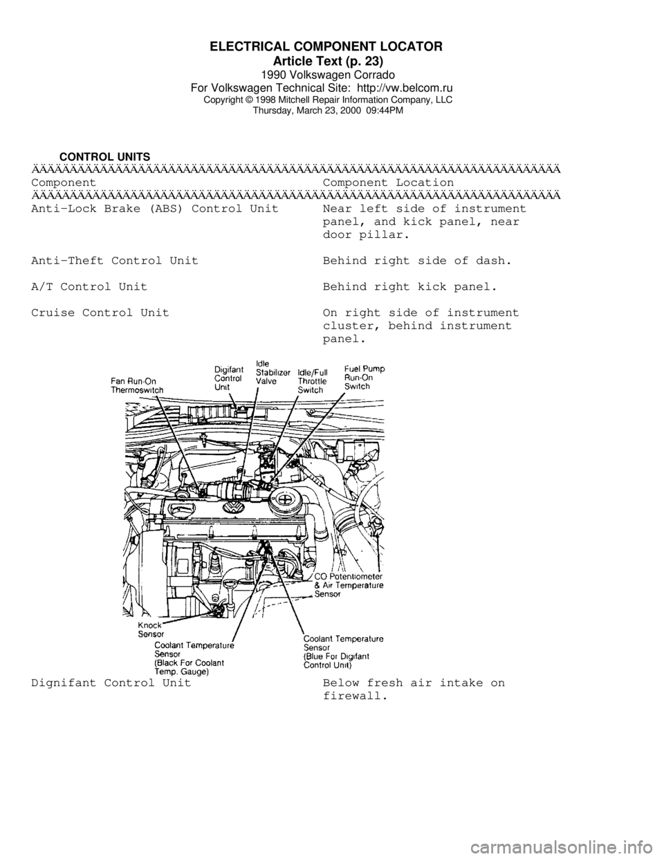
CONTROL UNITSÄÄÄÄÄÄÄÄÄÄÄÄÄÄÄÄÄÄÄÄÄÄÄÄÄÄÄÄÄÄÄÄÄÄÄÄÄÄÄÄÄÄÄÄÄÄÄÄÄÄÄÄÄÄÄÄÄÄÄÄÄÄÄÄÄÄÄÄÄÄComponent Component Location
ÄÄÄÄÄÄÄÄÄÄÄÄÄÄÄÄÄÄÄÄÄÄÄÄÄÄÄÄÄÄÄÄÄÄÄÄÄÄÄÄÄÄÄÄÄÄÄÄÄÄÄÄÄÄÄÄÄÄÄÄÄÄÄÄÄÄÄÄÄÄAnti-Lock Brake (ABS) Control Unit Near left side of instrument
panel, and kick panel, near
door pillar.
Anti-Theft Control Unit Behind right side of dash.
A/T Control Unit Behind right kick panel.
Cruise Control Unit On right side of instrument
cluster, behind instrument
panel.Dignifant Control Unit Below fresh air intake on
firewall.
Page 487 of 906

ELECTRICAL COMPONENT LOCATOR
Article Text (p. 28)
1990 Volkswagen Corrado
For Volkswagen Technical Site: http://vw.belcom.ru
Copyright © 1998 Mitchell Repair Information Company, LLC
Thursday, March 23, 2000 09:44PM
Fuel Gauge Sending Unit Mounted in top of fuel tank.
Hall Speed Sensor Rear of instrument cluster.
Heated Seat Temperature Sensor Below lower cushion of each
seat.Knock Sensor Mounted on cylinder block,
near dipstick.
Manifold Pressure Sensor In Digifant control unit,
below fresh air intake on
firewall.
Multi-Function Indicator
Vacuum Sensor Round sensor mounted on rear
of instrument cluster.
Oil Temperature Sending Unit Small sending unit above oil
filter (Green/Black wire
connector).
Oxygen Sensor In exhaust pipe, near
catalytic converter.
Vehicle Speed Sensor On transaxle.
Page 492 of 906
ELECTRICAL COMPONENT LOCATOR
Article Text (p. 33)
1990 Volkswagen Corrado
For Volkswagen Technical Site: http://vw.belcom.ru
Copyright © 1998 Mitchell Repair Information Company, LLC
Thursday, March 23, 2000 09:44PMÄÄÄÄÄÄÄÄÄÄÄÄÄÄÄÄÄÄÄÄÄÄÄÄÄÄÄÄÄÄÄÄÄÄÄÄÄÄÄÄÄÄÄÄÄÄÄÄÄÄÄÄÄÄÄÄÄÄÄÄÄÄÄÄÄÄÄÄÄÄ MISCELLANEOUS
ÄÄÄÄÄÄÄÄÄÄÄÄÄÄÄÄÄÄÄÄÄÄÄÄÄÄÄÄÄÄÄÄÄÄÄÄÄÄÄÄÄÄÄÄÄÄÄÄÄÄÄÄÄÄÄÄÄÄÄÄÄÄÄÄÄÄÄÄÄÄComponent Component Location
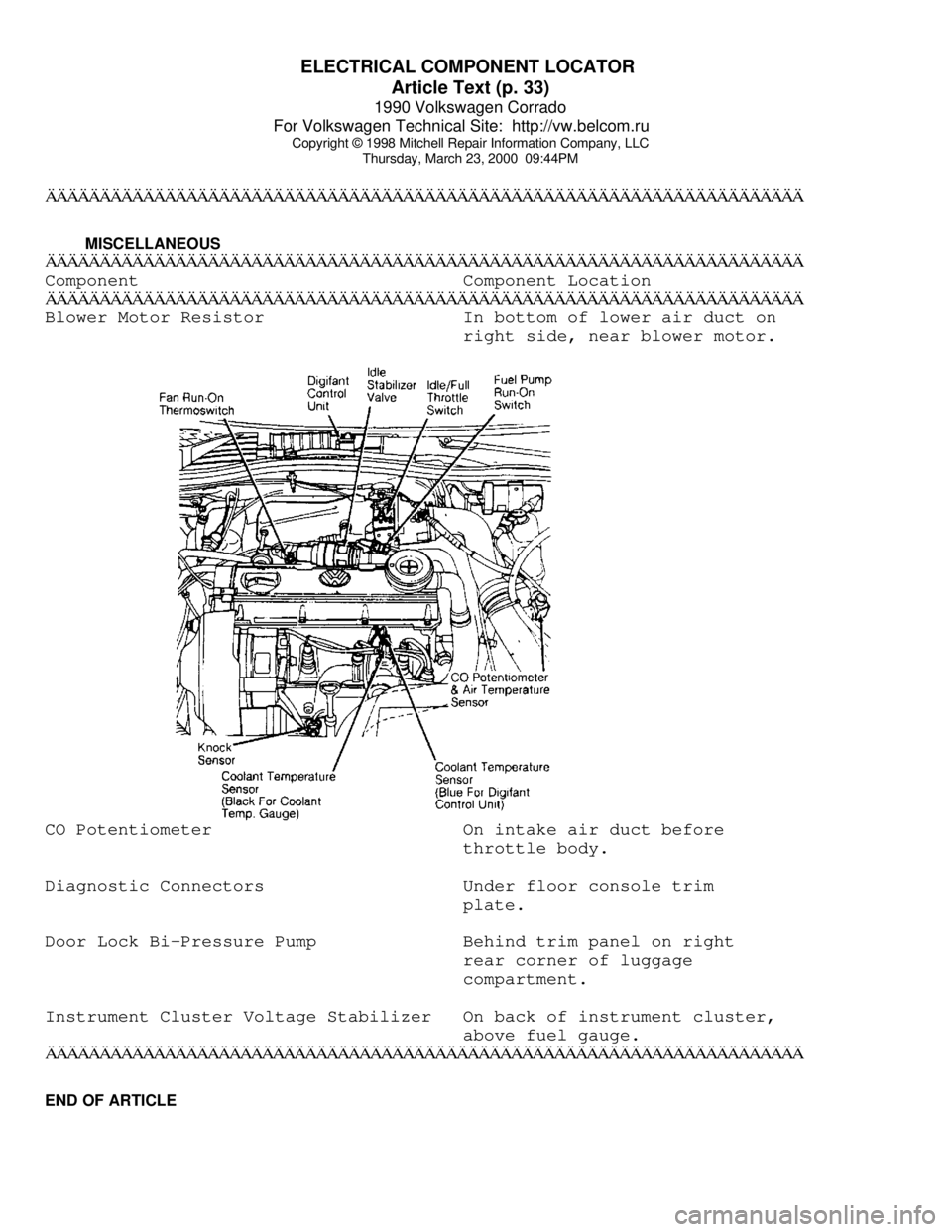
ÄÄÄÄÄÄÄÄÄÄÄÄÄÄÄÄÄÄÄÄÄÄÄÄÄÄÄÄÄÄÄÄÄÄÄÄÄÄÄÄÄÄÄÄÄÄÄÄÄÄÄÄÄÄÄÄÄÄÄÄÄÄÄÄÄÄÄÄÄÄBlower Motor Resistor In bottom of lower air duct on
right side, near blower motor.CO Potentiometer On intake air duct before
throttle body.
Diagnostic Connectors Under floor console trim
plate.
Door Lock Bi-Pressure Pump Behind trim panel on right
rear corner of luggage
compartment.
Instrument Cluster Voltage Stabilizer On back of instrument cluster,
above fuel gauge.
ÄÄÄÄÄÄÄÄÄÄÄÄÄÄÄÄÄÄÄÄÄÄÄÄÄÄÄÄÄÄÄÄÄÄÄÄÄÄÄÄÄÄÄÄÄÄÄÄÄÄÄÄÄÄÄÄÄÄÄÄÄÄÄÄÄÄÄÄÄÄEND OF ARTICLE
Page 585 of 906
HEATER SYSTEM
Article Text (p. 5)
1990 Volkswagen Corrado
For Volkswagen Technical Site: http://vw.belcom.ru
Copyright © 1998 Mitchell Repair Information Company, LLC
Thursday, March 23, 2000 09:45PM
retaining screws. Remove lower left instrument panel. Remove lower
right instrument panel tray retaining screws.
2) Remove lower right instrument panel. Remove gearshift
lever knob. Remove gearshift lever boot. Remove center console
retaining screws. Slide center console rearward. Disconnect electrical
connectors attached to center console. Remove center console.
3) Remove temperature control knobs. Remove trim plate.
Remove radio. Remove switches from instrument panel. Remove instrument
panel trim plate retaining screws. Remove instrument panel trim plate.
Remove instrument cluster retaining screws. Remove instrument cluster.
4) Disconnect speedometer cable, electrical connectors and
vacuum hoses from instrument cluster. Remove speaker grilles. Remove
air outlet grilles from housings. Remove housing retaining screws.
Remove air outlet housings. Remove instrument panel mounting nuts and
screws.
5) Remove instrument panel. Disconnect heater hoses from
heater core. Remove heater assembly mounting bolts and nuts. Remove
all attaching ducts. Disconnect cables from heater assembly. Remove
heater assembly.
INSTALLATION
Reverse removal procedure for installation. Fill radiator
with coolant and start engine. Ensure heater control is in warm
position to purge air from heater core.
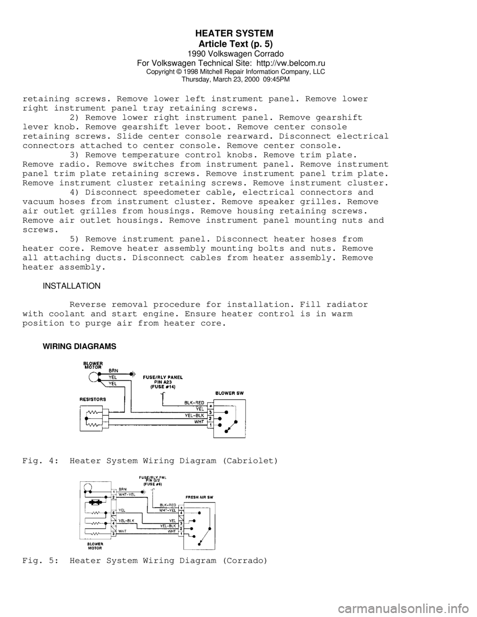
WIRING DIAGRAMSFig. 4: Heater System Wiring Diagram (Cabriolet)Fig. 5: Heater System Wiring Diagram (Corrado)
Page 603 of 906

INSTRUMENT PANEL
Article Text
1990 Volkswagen Corrado
For Volkswagen Technical Site: http://vw.belcom.ru
Copyright © 1998 Mitchell Repair Information Company, LLC
Thursday, March 23, 2000 09:46PM
ARTICLE BEGINNING
1989-90 ACCESSORIES & EQUIPMENT
Volkswagen Instrument Panels
Cabriolet, Fox, Golt, GTI, Jetta, Jetta GLI, Vanagon
DESCRIPTION & OPERATION
Instrument cluster for most models includes speedometer, fuel
gauge and temperature gauge. Optional instruments include clock,
tachometer, voltmeter and oil temperature gauge.
Printed circuit provides voltage to gauges. A voltage
regulator attached to the printed circuit controls voltage to fuel and
temperature gauges. Light Emitting Diodes (LEDs) are used for most
warning lights. To replace diodes, pull from printed circuit sockets.
NOTE: Volkswagen Tester (1301) is required for resistance tests.
Tester settings are numerical. Settings do not indicate
resistance in ohms. Manufacturer does not supply resistance
value in ohms.
TESTING
FUEL & TEMPERATURE GAUGE
1) Disconnect wire from fuel tank or temperature sending
unit. Connect VW tester between wire and ground. Turn ignition on and
allow 2 minutes for gauge reading to stabilize. Use FUEL GAUGE TESTING
or TEMPERATURE GAUGE TESTING table to compare gauge reading. Gauge
should be within one pointer width of specification.
2) If gauge needle does not move, check continuity between
sender wire and gauge. If needle moves, but does not match
specifications, replace gauge. If gauge works correctly with tester,
but not sending unit, replace sending unit.
FUEL GAUGE TESTINGÄÄÄÄÄÄÄÄÄÄÄÄÄÄÄÄÄÄÄÄÄÄÄÄÄÄÄÄÄÄÄÄÄÄÄÄÄÄÄÄÄÄÄÄÄÄÄÄÄÄÄÄÄÄÄApplication Dial Setting Indicator
Cabriolet & Fox .......... 55 ................ Full
560 ................Empty
Golf, GTI, Jetta
& Jetta GLI .............. 52 ................ Full
550 ................Empty
Vanagon .................. 50 ................ Full
320 ................Empty
ÄÄÄÄÄÄÄÄÄÄÄÄÄÄÄÄÄÄÄÄÄÄÄÄÄÄÄÄÄÄÄÄÄÄÄÄÄÄÄÄÄÄÄÄÄÄÄÄÄÄÄÄÄÄÄTEMPERATURE GAUGE TESTING
ÄÄÄÄÄÄÄÄÄÄÄÄÄÄÄÄÄÄÄÄÄÄÄÄÄÄÄÄÄÄÄÄÄÄÄÄÄÄÄÄÄÄÄÄÄÄÄÄÄÄÄÄÄÄÄ
Page 604 of 906
INSTRUMENT PANEL
Article Text (p. 2)
1990 Volkswagen Corrado
For Volkswagen Technical Site: http://vw.belcom.ru
Copyright © 1998 Mitchell Repair Information Company, LLC
Thursday, March 23, 2000 09:46PM
Application Dial Setting Indicator
Cabriolet ................ 500 ............... Cold
62 ...................Hot
Golf, GTI, Jetta,
Jetta GLI & Vanagon .... 510 ............... Cold
50 ...................HotÄÄÄÄÄÄÄÄÄÄÄÄÄÄÄÄÄÄÄÄÄÄÄÄÄÄÄÄÄÄÄÄÄÄÄÄÄÄÄÄÄÄÄÄÄÄÄÄÄÄÄÄÄÄÄ VOLTAGE REGULATOR
1) If only one gauge is inoperative, regulator is not
defective. If both fuel and temperature gauges are inoperative,
voltage regulator may be faulty or have a bad ground connection.
2) Partially remove instrument cluster. Position cluster so
regulator can be reached with voltmeter probes. Leave chassis harness
connected. Ensure ground connection at regulator is tight.
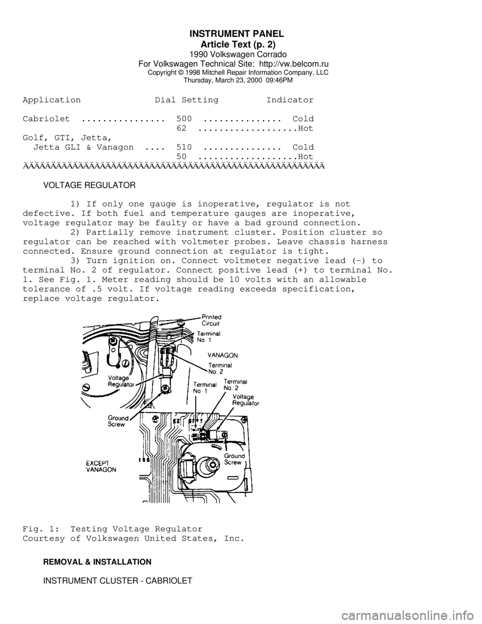
3) Turn ignition on. Connect voltmeter negative lead (-) to
terminal No. 2 of regulator. Connect positive lead (+) to terminal No.
1. See Fig. 1. Meter reading should be 10 volts with an allowable
tolerance of .5 volt. If voltage reading exceeds specification,
replace voltage regulator.Fig. 1: Testing Voltage Regulator
Courtesy of Volkswagen United States, Inc.
REMOVAL & INSTALLATION
INSTRUMENT CLUSTER - CABRIOLET