1990 MITSUBISHI SPYDER air condition
[x] Cancel search: air conditionPage 460 of 2103
![MITSUBISHI SPYDER 1990 Service Repair Manual ENGINE (NON-TURBO)>
Scan tool 160
Code General scan tool EVAP Leak Monitor
No.Detected
31
[Comment]
Background
l The PCM monitors that the fuel tank, purge lines, e tc. are MITSUBISHI SPYDER 1990 Service Repair Manual ENGINE (NON-TURBO)>
Scan tool 160
Code General scan tool EVAP Leak Monitor
No.Detected
31
[Comment]
Background
l The PCM monitors that the fuel tank, purge lines, e tc. are](/manual-img/19/57345/w960_57345-459.png)
ENGINE (NON-TURBO)>
Scan tool 160
Code General scan tool EVAP Leak Monitor
No.Detected
31
[Comment]
Background
l The PCM monitors that the fuel tank, purge lines, e tc. are well.
l
ventilation solenoid with the canister ventilation valve (incorporated in the lIf the fuel tank and purge lines are sealed the pressure will rise well by the solenoid specific timeslAfter the pressure rises well, the diaphragm inside the solenoid will not work any more.lIf the purge air leaks slightly, the solenoid will be activated more than specific times.
Range of Check, Set Condition
l The solenoid has been activated more than specific times.
‘ P r o b a b l e
I,
l Fuel tank cap screwed on l tank and purge lines, l Evaporative emission failed
l
l PCM failed’
NGCheck the evaporative Replace
(Refer to GROUP Emission Control System.)
OK
Check the evaporative emission purge solenoid.NG Replace
(Refer to GROUP 17 Emission Control System.)
OK
Check the fuel tank and purge line for leakage.
Scan tool 161
Code General scan tool EVAP Leak Monitor Large Leak
No. Detected
TSB Revision
[Comment]
l The PCM monitors that the fuel tank, purge lines, e tc. are well.
l
ventilation with the canister ventilation valve (incorporated in the solenoid) lIf the fuel tank and purge lines are sealed correct ly, the pressure will well by the solenoid specific times.lAfter the pressure rises well, the diaphragm inside the solenoid will not work any more.lIf the purge air leaks excessively, the solenoid should be activated much more than specific
times.
of Check. Set Condition
l been activated much more than specific times.
Probable cause
l Fuel tank filler cap screwed on lFuel tank and purge seated
l Evaporative solenoid
failed
l
l PCM ,
Check the evaporative emission ventilation solenoid .
(Refer to GROUP 17 Emission Control System.) Replace
NGCheck the evaporative emission purge solenoid. Replace
(Refer to GROUP 17 Emission Control System.)
OK
Check the fuel tank and line for I
Page 461 of 2103
![MITSUBISHI SPYDER 1990 Service Repair Manual ENGINE (NON-TURBO)>
Scan tool 183
Code General scan tool Evaporative Emission
No.tion Solenoid Circuit
31
[Comment]l Open or short control drcuitBackgroundl Open fused ignition MITSUBISHI SPYDER 1990 Service Repair Manual ENGINE (NON-TURBO)>
Scan tool 183
Code General scan tool Evaporative Emission
No.tion Solenoid Circuit
31
[Comment]l Open or short control drcuitBackgroundl Open fused ignition](/manual-img/19/57345/w960_57345-460.png)
ENGINE (NON-TURBO)>
Scan tool 183
Code General scan tool Evaporative Emission
No.tion Solenoid Circuit
31
[Comment]l Open or short control drcuitBackgroundl Open fused ignition l The PCM provides a switched ground path to the sole noid. Open or shorted solenoid lThis DTC indicates an open or short-circuit condition in the evaporative emission l PCM failed
solenoid control circuit.
Range of Check
l Battery voltage:
or more
l Ignition switch: ON
ConditionlOpen or short circuit is detected in the evaporativ e emission ventilation solenoid for 3seconds.
N GMeasure at the evaporative emission ventilation sol enoid connectorCheck the following connectors:
lDisconnect the connector and measure at the harness side.
l Voltage between 2 and ground
(Ignition switch: ON)
OK: Battery positive voltage
OKCheck the harness wire between ignition switch and emission ventilation solenoid connector. Repair,if
NGMeasure at the PCM connector Check the following connectors: lDisconnect the connector and measure at the harness side.
l Voltage between 77 and ground
(Ignition switch: ON)
OK: Battery positive voltage
OKCheck the harness wire between PCM and emissionventilation solenoid connector. Repair, if necessar y.
Check the following connector: Repair
Check trouble symptom.
N G
Replace the PCM.
TSB Revision
Page 462 of 2103
E N G I N E ( N O N - T U R B O ) > .
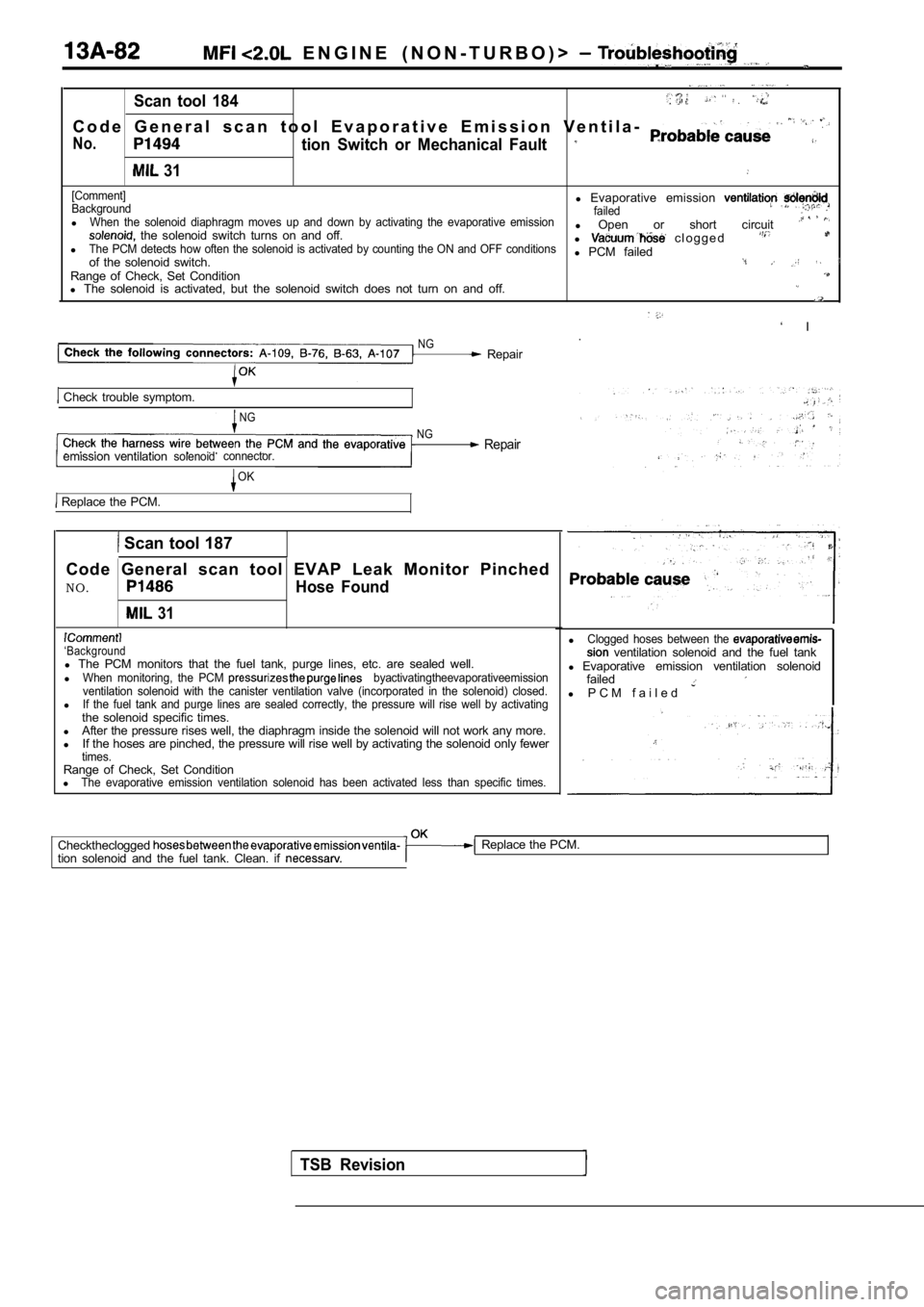
Scan tool 184. .
C o d e G e n e r a l s c a n t o o l E v a p o r a t i v e E m i s s i o n V e n t i l a-
No.tion Switch or Mechanical Fault
31
[Comment]
Backgroundl Evaporative emission failedlWhen the solenoid diaphragm moves up and down by ac tivating the evaporative emission the solenoid switch turns on and off. l
Open or short circuit lThe PCM detects how often the solenoid is activated by counting the ON and OFF conditionsl c l o g g e d
l PCM failed
of the solenoid switch.Range of Check, Set Conditionl The solenoid is activated, but the solenoid switch does not turn on and off.
‘ I
NG.
Repair
Check trouble symptom.
NG
NG
emission ventilation Repairsolenoidconnector.
OK
Replace the PCM.
Scan tool 187
Code General scan tool EVAP Leak Monitor Pinched
NO.
Hose Found
31
‘Backgroundl The PCM monitors that the fuel tank, purge lines, e tc. are sealed well.
lWhen monitoring, the PCM byactivatingtheevaporativeemission
ventilation solenoid with the canister ventilation valve (incorporated in the solenoid) closed.
lIf the fuel tank and purge lines are sealed correct ly, the pressure will rise well by activatingthe solenoid specific times.
l After the pressure rises well, the diaphragm inside the solenoid will not work any more.
l If the hoses are pinched, the pressure will rise we ll by activating the solenoid only fewer
times.Range of Check, Set Condition
lThe evaporative emission ventilation solenoid has b een activated less than specific times.
TSB Revision
lClogged hoses between the ventilation solenoid and the fuel tank
l Evaporative emission ventilation solenoid
failed
l P C M f a i l e d
Checktheclogged
tion solenoid and the fuel tank. Clean. if Replace the PCM.
Page 479 of 2103
![MITSUBISHI SPYDER 1990 Service Repair Manual ENGINE ( N O N - T U R B O ) >
INSPECTION PROCEDURE 25
Transaxle range sensor circuit
[Comment]The transaxle range sensor inputs the condition of the selector lever, i.e. whether it MITSUBISHI SPYDER 1990 Service Repair Manual ENGINE ( N O N - T U R B O ) >
INSPECTION PROCEDURE 25
Transaxle range sensor circuit
[Comment]The transaxle range sensor inputs the condition of the selector lever, i.e. whether it](/manual-img/19/57345/w960_57345-478.png)
ENGINE ( N O N - T U R B O ) >
INSPECTION PROCEDURE 25
Transaxle range sensor circuit
[Comment]The transaxle range sensor inputs the condition of the selector lever, i.e. whether it is in or range or in some other range, to the PCM.
The PCM controls the idle air control motor based o n this input.Improper connector contact, open circuit
Check the transaxle range sensor. (Refer to GROUP On-vehicle Service.) Replace.
lDisconnect the connector,and measure atthe harness
A-l
OK
Check trouble symptom.
OK
Replace the PCM.
Check harness wire betweenN G
PCM transaxle rangesensor connector.
O K
Replace the PCM.
,
INSPECTION PROCEDURE 26
A/C switch and A/C compressor clutch relay system
motor, and also operates the A/C compressor magneti c clutch.Probable cause
l Malfunction of A/C control l Malfunction of A/C switch Improper connector open short-circuited harness wire
l Malfunction of PCM
NG
OKCheck the A/C compressor clutch relay.
Measure at the PCM
l
(Refer to GROUP 55 On-vehicle Service.)
Disconnect the connector, and measure at the harnes s
Replace
Check the
system. (Refer to GROUP 55
side.lVoltage between 64 and ground, and 38 and ground(Ignition switch: ON)
(A/C switch: ON)
OK: Battery positive voltage
l Connect a jumper wire between 64 and ground.
(Ignition switch: ON)
(A/C switch: ON)
OK: A/C compressor clutch turns ON.
OK1NG RepairA-l 06,A-l 07
OK
Check trouble symptom.
Replace the PCM.
NG
TSB Revision
Page 492 of 2103
ENGINE (NON-TURBO)> Troubleshooting
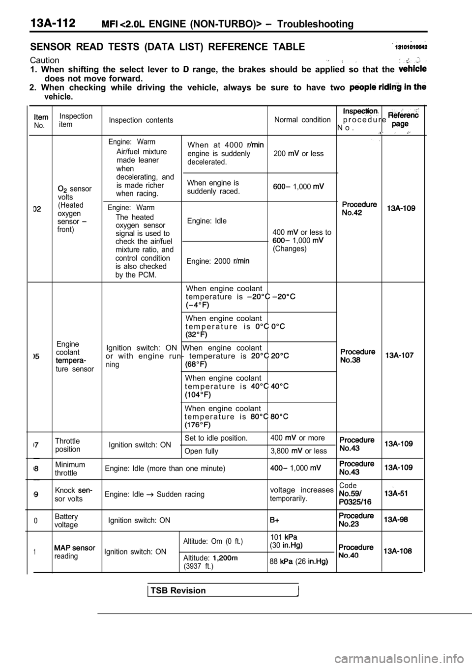
SENSOR READ TESTS (DATA LIST) REFERENCE TABLE
Caution
1. When shifting the select lever to range, the brakes should be applied so that the
does not move forward.
2. When checking while driving the vehicle, always be sure to have two
vehicle.
Inspection
No.itemInspection contents
Normal conditionp r o c e d u r e
N o .
Engine: WarmWhen at 4000 Air/fuel mixture
engine is suddenly 200 or less
made leaner
decelerated.when
decelerating, and
sensor is made richer
When engine is 1,000
voltswhen racing.
suddenly raced.
(Heated
oxygenEngine: Warm
The heatedsensoroxygen sensor Engine: Idlefront)signal is used to
400 or less to
check the air/fuel
1,000
mixture ratio, and (Changes)
control condition is also checked Engine: 2000
by the PCM.
When engine coolant
t e m p e r a t u r e i s
When engine coolant
t e m p e r a t u r e i s
Engine
coolantIgnition switch: ON When engine coolant
or with engine run- temperature is
ture sensorning
When engine coolant
t e m p e r a t u r e i s
When engine coolant
t e m p e r a t u r e i s
Throttle Set to idle position.
400 or more
position Ignition switch: ON
Open fully 3,800
or less
Minimum
throttle Engine: Idle (more than one minute) 1,000
KnockCode
sor voltsEngine: Idle Sudden racingvoltage increases
temporarily.
0Battery
voltage Ignition switch: ON
101
1
Altitude: Om (0 ft.)
reading
Ignition switch: ON (30Altitude:
(3937 ft.)88 (26
TSB Revision
Page 493 of 2103
ENGINE (NON-TURBO)>
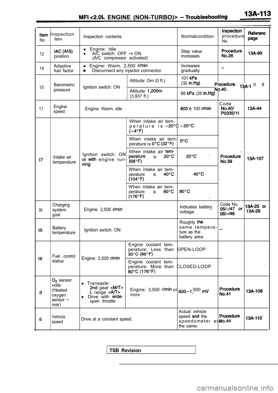
I n s p e c t i o n
itemNo.Inspection contentsNormalconditionp r o c e d u r e
No.
12position
l Engine: IdlelA/C switch: OFF ON(A/C compressor activated) Step value
increases.
14
15
17
Adaptivel Engine: Warm, 2,500 Increases
fuel factor
Disconnect any injector connector. gradually
Altitude: Om (0 ft.) 101Barometric
Ignition switch: ON (30
pressureAltitude:
0 8
(3,937 ft.)
88 (26
C o d eEngine
speedEngine: Warm, idle 100
When intake air tem-
p e r a t u r e i s
When intake air tern-
perature is
When intake air
Intake airIgnition switch: ON
e n g i n e r u n - is
temperature
When intake air tem-
peratureis
36
Charging
system
goal
When intake air tem-
peratureis
Code No.
Engine: 2,500 Indicates battery
voltage
Roughly
Batterys a m e t e m p e r a -
temperature Ignition switch: ON
ture as the
battery area
Engine coolant tem-
perature: Less than OPEN-LOOP
Fuel control
status Engine: 2,500 Engine coolant tem-
.
perature: More than CLOSED-LOOP
sensor
volts
(Heated
oxygen
sensor
rear)
l Transaxle: gear Engine: 3,500 or 000 range l Drive with more
open throttle
Actual vehicle
Vehicle
speedDrive at a constant speed. speed the
s p e e d o m e t e r a r e .
the same.
TSB Revision
Page 494 of 2103
ENGINE (NON-TURBO)> Troubleshooting
,
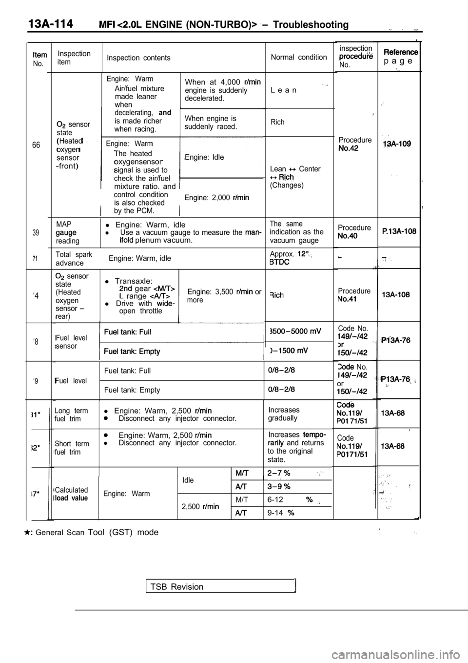
p a g eNo.
66
39
71
inspection
No.
Procedure
Inspection
itemInspection contentsNormal condition
Engine: Warm
Air/fuel mixture
made leaner
whenWhen at 4,000
engine is suddenly
decelerated.L e a n
sensor
state
(Heated
oxygen
sensor
-front)
decelerating,and
is made richer When engine is
when racing. suddenly raced.
Engine: Warm
The heated
oxygensensorEngine: Idle
signal is used to
check the air/fuel
Rich
Lean Center
(Changes)mixture ratio. and
control condition is also checked Engine: 2,000
by the PCM.
MAPl
Engine: Warm, idleThe same
lUse a vacuum gauge to measure the indication as the
reading plenum vacuum.vacuum gauge Procedure
Procedure
Total spark
advance
Engine: Warm, idle
Approx.
sensor
state
(Heated
oxygen
sensor
rear)
l Transaxle: gear range l Drive with open throttle Engine: 3,500
or‘4more
Code No.
No.
or
Fuel level
sensor‘8
Fuel level
Fuel tank: Full
Fuel tank: Empty
‘9
Code
Long terml
Engine: Warm, 2,500 Increases
fuel trimDisconnect any injector connector. gradually
Engine: Warm, 2,500
Short termlDisconnect any injector connector. Increases and returns
fuel trimto the original
state.
Idle
Calculated
load valueEngine: Warm M/T
2,5006-12
9-14
General Scan Tool (GST) mode
TSB Revision
Page 518 of 2103
ENGINE
AND ENGINE> G e n e r a l
ENGINE (TURBO) AND ENGINE>13199910319
GENERAL INFORMATIONThe
Fuel Injection System consists
of sensors which detect the engine conditions,
the ENGINE CONTROL MODULE (ECM) which
controls the system based on signals from these
sensors, and actuators which operate under
the control of the ECM.
FUEL INJECTION CONTROL
The injector drive times and injector timing are
controlled so that the optimum air/fuel mixture
is supplied to the engine to correspond to the
continually-changing engine operation condi-
tions.
A single injector is mounted at the intake port
of each cylinder. Fuel is sent under pressure
from the fuel tank by the fuel pump, with the
pressure regulated by the fuel pressure regula-
tor. The regulated fuel is distributed to each
of the injectors.
Fuel injection is normally carried out once for
each cylinder for every two rotations of the
IDLE AIR CONTROL The idle speed is kept at the optimum speed
by controlling the amount of air that bypasses
the throttle valve in accordance with changes
in idling conditions and engine load during id-
ling.
The ECM drives the idle air control (IAC) motor
to keep the engine running at the pre-set idle
target speed in accordance with the engine
IGNITION TIMING CONTROL
The ignition power transistor located in the igni-
tion primary circuit turns ON and OFF to control
the primary current flow to the ignition coil.
This controls the ignition timing in order to pro-
vide the optimum ignition timing with respect The ECM carries out activities such as fuel
injection control, idle air control and ignition
timing control.
In addition, the ECM is equipped with several
diagnostic test modes which simplify trouble-
shooting when a problem develops.
. .
crankshaft. The firing is This
is called
The provides a richer
air/fuel mixture by carrying out “open-loop” con-
trol when the engine is cold or operating under high load
in order to maintain engine
performance. In addition, when the engine is warm or operat-
ing under normal conditions, the ECM controls
the air/fuel mixture by using the heated oxygen
sensor signal to carry out “closed-loop” control
in order to obtain the theoretical air/fuel mixture
ratio that provides the maximum cleaning per-
formance from the three way catalyst.
coolant temperature and air conditioning load.
In addition, when the air’ conditioning switch
is turned off and on while the
is
the motor operates to adjust the throttle
valve bypass air amount in accordance with
the engine load conditions in order to avoid
fluctuations in the engine speed.
to the engine operating conditions. The ignition
timing is determined by the ECM from the en-
gine speed, intake air volume, engine coolant
temperature and atmospheric pressure.
TSB Revision