Page 725 of 2103
INTAKE AND EXHAUST Intake Manifold Engine
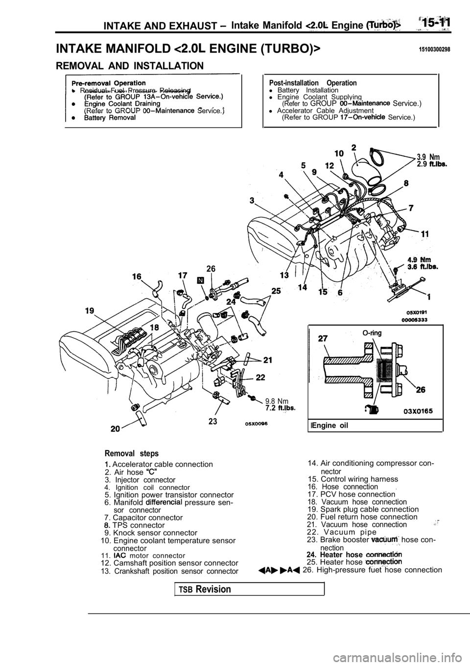
INTAKE MANIFOLD ENGINE (TURBO)>15100300298
REMOVAL AND INSTALLATION
l Residual Fuel Pressure Releasing
(Refer to GROUP
Service.)
26
Post-installation Operationl Battery Installation
l Engine Coolant Supplying
(Refer to GROUP Service.)l Accelerator Cable Adjustment
(Refer to GROUP Service.)
3.9 Nm2.9
9.8 Nm7.2
23
Removal steps
Accelerator cable connection
2. Air hose
3. Injector connector4. Ignition coil connector 5. Ignition power transistor connector
6. Manifold
pressure sen-sor connector
14. Air conditioning compressor con-
7. Capacitor connector
TPS connector
9. Knock sensor connector
10. Engine coolant temperature sensor
connector11. motor connector
12. Camshaft position sensor connector
13. Crankshaft position sensor connector nector
15. Control wiring harness16. Hose connection.17. PCV hose connection18. Vacuum hose connection19. Spark plug cable connection
20. Fuel return hose connection
21. Vacuum hose connection2 2 . V a c u u m p i p e
23. Brake booster hose con-
nection24. Heater hose 25. Heater hose 26. High-pressure fuet hose connection
IEngine oil
TSBRevision
Page 728 of 2103
INTAKE AND EXHAUST Intake Manifold
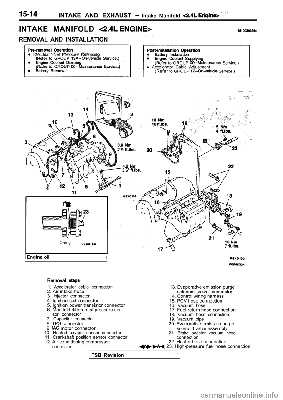
INTAKE MANIFOLD
REMOVAL AND INSTALLATION
l Residual Fuel Pressure Releasing
(Refer to GROUP
Service.) (Refer to GROUP Service.)
l Accelerator Cable Adjustment
(Refer to GROUP
Service.)
2.9
4.9 Nm 3.6’ 15
O-ring
Engine oilI
18
10 Nm7
Removal
1. Accelerator cable connection2. Air intake hose3. Injector connector4. Ignition coil connector
5. Ignition power transistor connector
6. Manifold differential pressure sen-
sor connector
7. Capacitor connector
8. TPS connector
9. motor connector
10. Heated oxygen sensor connector
11. Crankshaft position sensor connector12. Air conditioning compressor
connector
13. Evaporative emission purge
solenoid valve connector .
14. Control wiring harness
15. PCV hose connection
16. Vacuum hose17. Fuel return hose connection18. Vacuum hose connection
19. Vacuum pipe
20. Evaporative emission purge solenoid valve assembly
21. Brake booster vacuum hose
connection22. Heater hose connection 23. High-pressure fuel hose connection
TSB Revision
Page 753 of 2103
ENGINE AND EMISSION CONTROL Auto-cruise
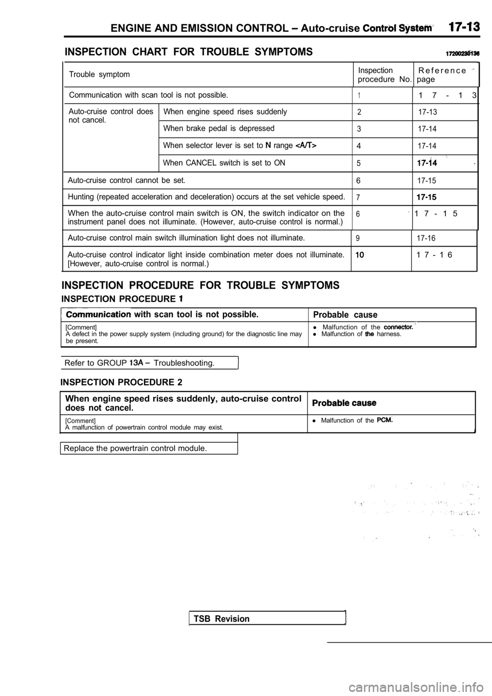
INSPECTION CHART FOR TROUBLE SYMPTOMS
Trouble symptomInspectionR e f e r e n c e
procedure No. page
Communication with scan tool is not possible.11 7 - 1 3
Auto-cruise control doesWhen engine speed rises suddenly217-13not cancel.
When brake pedal is depressed
3 17-14
When selector lever is set to range 417-14
When CANCEL switch is set to ON5.
Auto-cruise control cannot be set. 617-15
Hunting (repeated acceleration and deceleration) occurs at the set vehicle speed.7
When the auto-cruise control main switch is ON, the switch indicator on the6 1 7 - 1 5instrument panel does not illuminate. (However, aut o-cruise control is normal.)
Auto-cruise control main switch illumination light does not illuminate.
917-16
Auto-cruise control indicator light inside combinat ion meter does not illuminate.1 7 - 1 6
[However, auto-cruise control is normal.)
INSPECTION PROCEDURE FOR TROUBLE SYMPTOMS
INSPECTION PROCEDURE
with scan tool is not possible.
Probable cause
[Comment] l
Malfunction of the A defect in the power supply system (including grou nd) for the diagnostic line mayl Malfunction of harness.
be present.
Refer to GROUP
Troubleshooting.
INSPECTION PROCEDURE 2 When engine speed rises suddenly, auto-cruise contr ol
does not cancel.
[Comment]A malfunction of powertrain control module may exist.
Replace the powertrain control module. l
Malfunction of the
TSB Revision
Page 754 of 2103
![MITSUBISHI SPYDER 1990 Service Repair Manual ENGINE AND EMISSION CONTROL Auto-cruise Control System
INSPECTION PROCEDURE 3
When brake pedal is depressed,, auto-cruise control does not
cancel.
[Comment]A malfunction of the stop li MITSUBISHI SPYDER 1990 Service Repair Manual ENGINE AND EMISSION CONTROL Auto-cruise Control System
INSPECTION PROCEDURE 3
When brake pedal is depressed,, auto-cruise control does not
cancel.
[Comment]A malfunction of the stop li](/manual-img/19/57345/w960_57345-753.png)
ENGINE AND EMISSION CONTROL Auto-cruise Control System
INSPECTION PROCEDURE 3
When brake pedal is depressed,, auto-cruise control does not
cancel.
[Comment]A malfunction of the stop light switch or stop ligh t circuit may exist.
Probable cause
l Malfunction of the stop light switch.
l Malfunction of the connector.
l Malfunction of the
l Malfunction of the PCM.
Stop light switch check.
(Refer to
OK
Measure at stop
switch connector
lDisconnect the connector and mea-sure at the harness side.
l Voltage between terminal (1) and
ground positive voltage
following connectors:
NG
63 and
NG
Check troubleNGsymp Check the l i g h t a n d P C M . R e p a i r ,
OK Check trouble symptom.
Replace the PCM.
light switch and the
ground.
,
INSPECTION PROCEDURE 4
When selector lever is set to range, auto-cruise control does
not cancel.
[Comment]An open-circuit in the output signal circuit in IN range may be present.
OK
and.
TSB Revision
Inspect thebetween the NG
transaxle range switch and PCM.
OK
the PCM.
INSPECTION PROCEDURE 5
When auto-cruise control CANCEL switch is set to ON ,
auto-cruise control does not cancel. Probable cause
[Comment]An open-circuit inside the CANCEL switch may be pre
sent.l
Malfunction of the auto-cruise control switch.
Replace the auto-cruise control
Page 759 of 2103
AND CONTROL
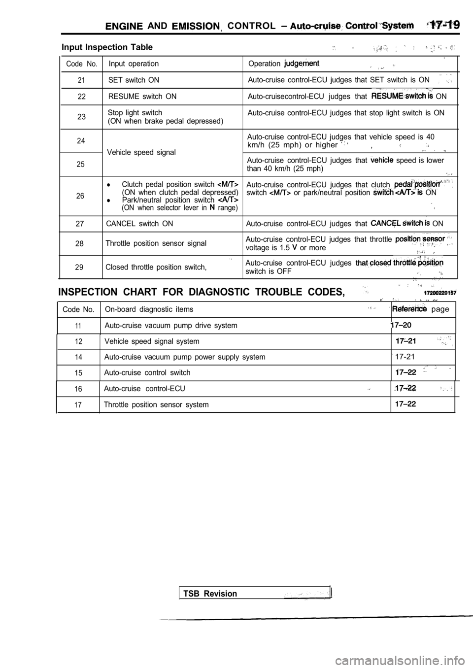
Input Inspection Table
.
Code No.Input operation Operation
21SET switch ONAuto-cruise control-ECU judges that SET switch is O
N
22RESUME switch ON Auto-cruisecontrol-ECU judges that ON
23 Stop light switch
(ON when brake pedal depressed) Auto-cruise control-ECU judges that stop light swit
ch is ON
24
25
26Auto-cruise control-ECU judges that vehicle speed i s 40
km/h (25 mph) or higher ,Vehicle speed signal
Auto-cruise control-ECU judges that speed is lower
than 40 km/h (25 mph)
lClutch pedal position switch Auto-cruise control-ECU judges that clutch (ON when clutch pedal depressed) Park/neutral position switch switch or park/neutral position ONl(ON when selector lever in range)
27 CANCEL switch ON Auto-cruise control-ECU judges that
ON
28 Throttle position sensor signal Auto-cruise control-ECU judges that throttle
voltage is 1.5 or more
29Closed throttle position switch,Auto-cruise control-ECU judges
switch is OFF
INSPECTION CHART FOR DIAGNOSTIC TROUBLE CODES,
Code No.
On-board diagnostic items page
11Auto-cruise vacuum pump drive system
12
14
15
Vehicle speed signal system
Auto-cruise vacuum pump power supply system
Auto-cruise control switch
17-21
.
16
17
Auto-cruise control-ECU
Throttle position sensor system
TSB Revision
Page 763 of 2103
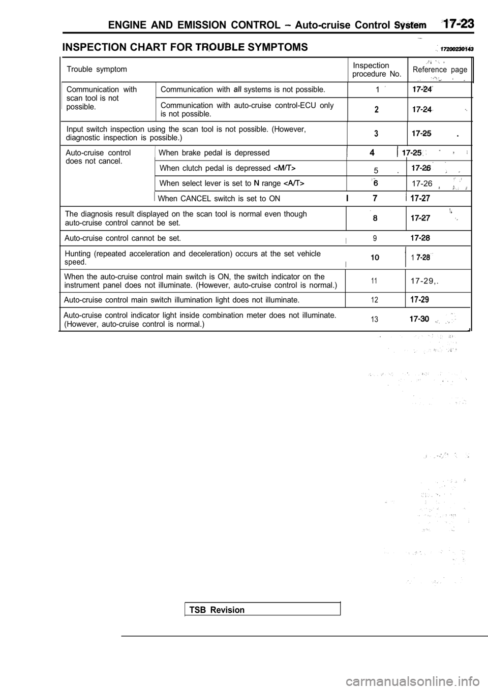
ENGINE AND EMISSION CONTROL Auto-cruise Control
INSPECTION CHART FOR SYMPTOMS
Communication with
scan tool is not
possible. Communication with systems is not possible.
Communication with auto-cruise control-ECU only
is not possible.1
2
Input switch inspection using the scan tool is not possible. (However,
diagnostic inspection is possible.)3 .
Auto-cruise control When brake pedal is depressed 4 does not cancel. When clutch pedal is depressed
When select lever is set to range
When CANCEL switch is set to ON
5
17-26
I 7 17-27
Trouble symptomInspection
procedure No.Reference page
The diagnosis result displayed on the scan tool is normal even though
auto-cruise control cannot be set.
Auto-cruise control cannot be set.I9
Hunting (repeated acceleration and deceleration) oc curs at the set vehicle
speed.I1
When the auto-cruise control main switch is ON, the switch indicator on the
instrument panel does not illuminate. (However, aut o-cruise control is normal.)
Auto-cruise control main switch illumination light does not illuminate.111 7 - 2 9 , .
1217-29
Auto-cruise control indicator light inside combinat ion meter does not illuminate.
(However, auto-cruise control is normal.)13
TSB Revision
Page 765 of 2103
![MITSUBISHI SPYDER 1990 Service Repair Manual ENGINE AND EMISSION System
.,
INSPECTION PROCEDURE 3
Input switch inspection using the scan tool is pdssible.
(However, diagnostic inspection is possible.)
I
[Comment]A malfunction MITSUBISHI SPYDER 1990 Service Repair Manual ENGINE AND EMISSION System
.,
INSPECTION PROCEDURE 3
Input switch inspection using the scan tool is pdssible.
(However, diagnostic inspection is possible.)
I
[Comment]A malfunction](/manual-img/19/57345/w960_57345-764.png)
ENGINE AND EMISSION System
.,
INSPECTION PROCEDURE 3
Input switch inspection using the scan tool is pdssible.
(However, diagnostic inspection is possible.)
I
[Comment]A malfunction of auto-cruise control switch circuit system may be present.l
Malfunction of the auto-cruise control l Malfunction of the clock spring .
l of the connector.
l Malfunction of the harness.
.
NG
(Refer to
Measure at clock spring connector
l sure at the harness side
l Voltage between terminal (2) and
groundOK: Battery positive voltage
OK
Check trouble symptom.
C h e c k t r o u b l e spring and auto-cruise
INSPECTION PROCEDURE 4
When brake pedal is depressed, auto-cruise control does not
cancel.Probable , ,
[Comment]A malfunction of stop light switch or a malfunction of stop light circuit may be present.l
Malfunction of the stop light switch.
l Malfunction of the connector.
l Malfunction of. the
l Malfunction of the auto-cruise control-ECU.
Does stop
illuminate?
No
Replace the auto-cruise control-ECU.
lDisconnect the connector and mea-sure at the harness side.
Check trouble symptom.Check the following connectors:
TSB Revision
Page 772 of 2103
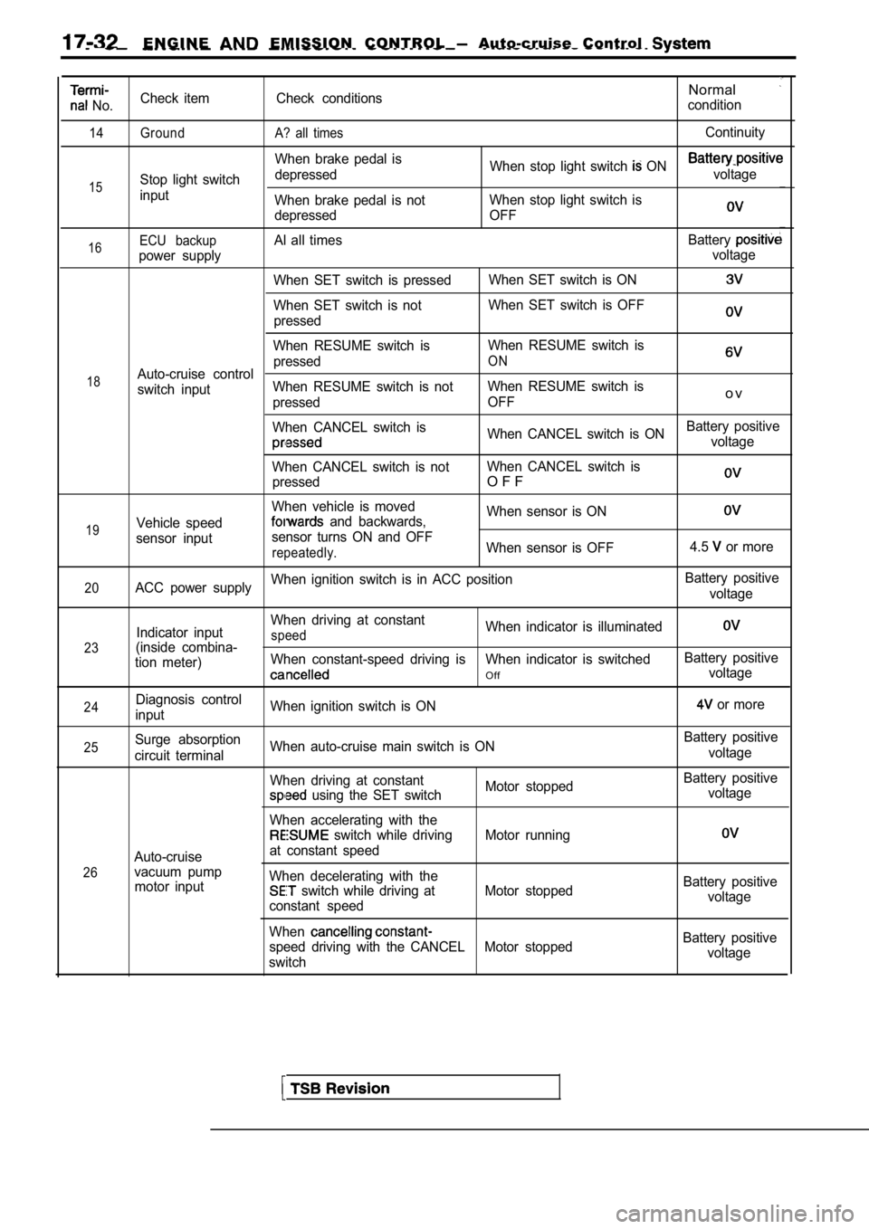
E N G I N E EMISSION CONTROL Auto-cruise Control
No.
14
15
Check item
Ground
Stop light switch
inputCheck conditions
A? all times
When brake pedal is
depressed
When brake pedal is not
depressed
Normal
condition
Continuity
When stop light switch ON voltage
When stop light switch is
OFF
16
18
19ECU backupAl all times Battery
power supply voltage
When SET switch is pressed When SET switch is ON
When SET switch is notWhen SET switch is OFF
pressed
When RESUME switch is When RESUME switch is
pressed
ONAuto-cruise control
switch input When RESUME switch is not
When RESUME switch is
pressed OFF
o v
When CANCEL switch is
When CANCEL switch is ONBattery positivevoltage
When CANCEL switch is not When CANCEL switch is
pressed
O F F
When vehicle is moved When sensor is ON
Vehicle speed and backwards,
sensor input sensor turns ON and OFF
repeatedly.When sensor is OFF
4.5 or more
20ACC power supplyWhen ignition switch is in ACC position
Battery positive
voltage
23
24
Indicator input
(inside combina-
tion meter)
Diagnosis control
input When driving at constantspeedWhen indicator is illuminated
When constant-speed driving is When indicator is swi
tchedBattery positive
Offvoltage
When ignition switch is ON
or more
25
26Surge absorption
circuit terminal
Auto-cruise
vacuum pump motor input When auto-cruise main switch is ON
When driving at constant
Motor stopped
using the SET switch
When accelerating with the
switch while driving Motor running
at constant speed
When decelerating with the
switch while driving at Motor stopped
constant speed
When
speed driving with the CANCEL Motor stopped
switch Battery positive
voltage
Battery positive voltage
Battery positivevoltage
Battery positive voltage