Page 776 of 2103

17-36ENGINE AND EMISSION CONTROL Auto-cruise Control System
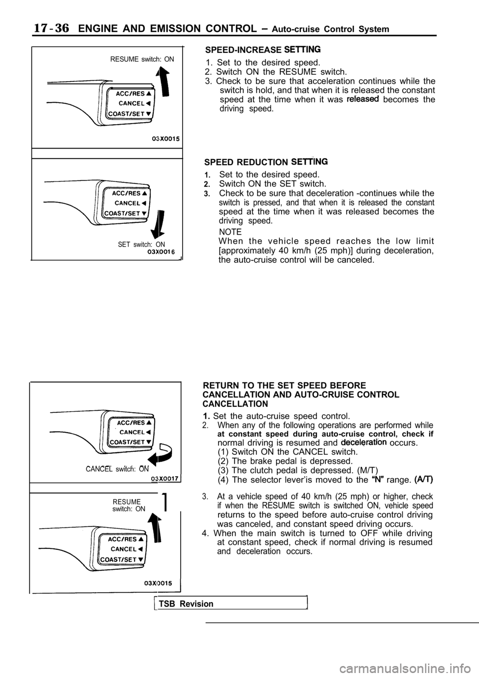
RESUME switch: ON
SET switch: ON 6
CANCEL switch: ON
RESUMEswitch: ON1
SPEED-INCREASE
1. Set to the desired speed.
2. Switch ON the RESUME switch. 3. Check to be sure that acceleration continues whi le the
switch is hold, and that when it is released the co nstant
speed at the time when it was
becomes the
driving speed.
SPEED REDUCTION
1.
2.
3.
Set to the desired speed.
Switch ON the SET switch.
Check to be sure that deceleration -continues while the
switch is pressed, and that when it is released the constant
speed at the time when it was released becomes the
driving speed.
NOTE
W h e n t h e v e h i c l e s p e e d r e a c h e s t h e l o w l i m i t[approximately 40 km/h (25 mph)] during deceleratio n,
the auto-cruise control will be canceled.
RETURN TO THE SET SPEED BEFORE
CANCELLATION AND AUTO-CRUISE CONTROL
CANCELLATION
1. Set the auto-cruise speed control.
2.When any of the following operations are performed while
at constant speed during auto-cruise control, check if
normal driving is resumed and
occurs.
(1) Switch ON the CANCEL switch.
(2) The brake pedal is depressed.
(3) The clutch pedal is depressed. (M/T)
(4) The selector lever’is moved to the
range.
3.At a vehicle speed of 40 km/h (25 mph) or higher, c heck
if when the RESUME switch is switched ON, vehicle s peed
returns to the speed before auto-cruise control driving
was canceled, and constant speed driving occurs.
4. When the main switch is turned to OFF while driv ing
at constant speed, check if normal driving is resum ed
and deceleration occurs.
TSB Revision
Page 777 of 2103
ENGINE AND EMISSION CONTROL Auto-cruise Control System
CONTROL COMPONENT
STOP LIGHT SWITCH
MeasurementFor stop lightFor
conditionscircuitcontrol circuit
terminal No.
terminal
2314
When brake pedal
depressed.0
When brake pedal notdepressed.0 0
CLUTCH PEDAL POSITION SWITCH
Engine (Turbo) and Engine
Measurement conditions
When clutch pedal depressed.Terminal No.
12
0
When clutch pedal not depressed.
PARK/NEUTRAL POSITION SWITCH POSITION)
Engine (Turbo) and Engine>
Measurement Terminal No.Iconditions Engine (Turbo)7 8I
Engine
Selector lever is not at position
Selector lever is at
position 5
8
0
AUTO-CRUISE VACUUM PUMP (Turbo)
and
Engine>
1. Disconnect the vacuum hose from
vacuum
pump and connect a vacuum the vacuum pump.
2. Disconnect the electric vacuum pump connector.
TSB Revision
Page 833 of 2103
CLUTCH Service Specifications/Lubricants
SERVICE SPECIFICATIONS
Clutch pedal height mm (in.)
Clutch pedal
pin play mm (in.)
Clutch pedal free play mm (in.) Distance between the clutch pedal and
the
when the clutch is disengaged mm (in.)
LUBRICANTS
Standard value
6-13
70 (2.76) or more
Items
Clutch fluid
Push rod assembly
Boot
Specified lubricants
Brake Fluid DOT 3 or DOT 4
Rubber grease
Q u a n t i t y
A s r e q u i r e d
As required
Release cylinder push rod MITSUBISHI genuine grease
Part No. 0101011 or equivalentAs required
Clutch pedal shaft, bushings and end of the Brake grease SAE
No. 1As required
pedal
Clutch master cylinder push rod, pin
and washer
Clutch release cylinder
pin
Revision
Page 836 of 2103

CLUTCH On-vehicle Service
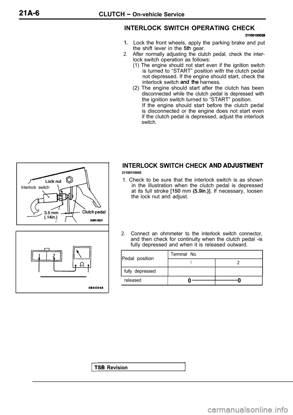
Interlock switch
Revision
INTERLOCK SWITCH OPERATING CHECK
1.
2.
Lock the front wheels, apply the parking brake and put
the shift lever in the
gear.
After normally adjusting the clutch pedal, check th e inter-
lock switch operation as follows:
(1) The engine should not start even if the ignition switch
is turned to “START” position with the clutch pedal
not depressed. If the engine should start, check th e
interlock switch
harness.
(2) The engine should start after the clutch has be en
disconnected while the clutch pedal is depressed with
the ignition switch turned to “START” position.
If the engine should start before the clutch pedal
is disconnected or the engine does not start even
if the clutch pedal is depressed, adjust the interl ock
switch.
INTERLOCK SWITCH CHECK
21100110045
1. Check to be sure that the interlock switch is as shown
in the illustration when the clutch pedal is depres sed
at its full stroke
mm If necessary, loosen
the lock nut and adjust.
2.Connect an ohmmeter to the interlock switch connect or,
and then check for continuity when the clutch pedal -is
fully depressed and when it is released outward.
Terminal No.Pedal position12
fully depressed
released0I0
Page 837 of 2103
CLUTCH On-vehicle Service
Engine (Non-turbo)>
Engine (Turbo) and
BLEEDING
Whenever the clutch tube, the clutch clutch
master cylinder have or the clutch pedal
is spongy, bleed the system.
Specified brake fluid: DOT 3 or 4
Caution
Use only the specified brake fluid. Do not mix with
fluid.
TSB Revision
Page 843 of 2103
CLUTCHClutch Master Cylinder. . .
CLUTCH MASTER CYLINDER
DISASSEMBLY AND REASSEMBLY
Piston repair kitBrake fluid DOT 3 or
DOT 4Grease:Rubber
(Non-turbo)
Engine (Turbo)>
Disassembly steps
1. Piston stopper ring rod assembly
Piston assembly
5. Return spring
6.Reservoir hose
121 mm (4.8 in.)
7.Reservoir cap8. Reservoir tank
9. Reservoir band
10. Nipple11. Clutch master cylinder body
INSTALLATION SERVICE POINT
PUSH ROD ASSEMBLY INSTALLATION
NOTE
Set the length of the push rod assembly to the shown
dimension to make the adjustment of the clutch peda l easier.
0 8 2 0 0 0 4
INSPECTION
lCheck the inside cylinder body for rust or scars.
lCheck the piston cup for wear or deformation.
lCheck the piston rust or scars.
lCheck the clutch pipe connection for clogging.
TSB Revision
Page 847 of 2103
CLUTCH OVERHAUL Specifications
LUBRICANTS
Engine (Turbo) and Engine>
ISpecified lubricants
Clutch release cylinder inner surface
Piston and cup of surface
Release fork fulcrum Brake Fluid or
Mitsubishi genuine grease
No. 0101011 or equivalent
Clutch release fork to release cylinder contact sur face
Clutch release bearing inside
Clutch disc spline
Clutch release bearing to release fork contact surf ace
Engine (Non-turbo)>
Items
Clutch flywheel assembly splineSpecified lubricantsMitsubishi genuine grease Part
No. or equivalent
Clutch release release cylinder contact surface
Clutch release lever to release bearing contact su rface
As required
As required
TSB Revision
Page 854 of 2103
(Turbo)
CLUTCH RELEASE CYLINDER Engine (Turbo) and
Engine>
DISASSEMBLY AND REASSEMBLY
21200150057
Brake fluid or
8.0
TSB Revision
Disassembly steps
1. Push rod
2. Boot
3. Piston cup
4. Piston
4
q31
2
5Piston
IBrake fluid or
5. Conical spring6. Cap
7. Bleeder plug
8. Release cylinder