Page 1567 of 2103

REAR AXLE Differential
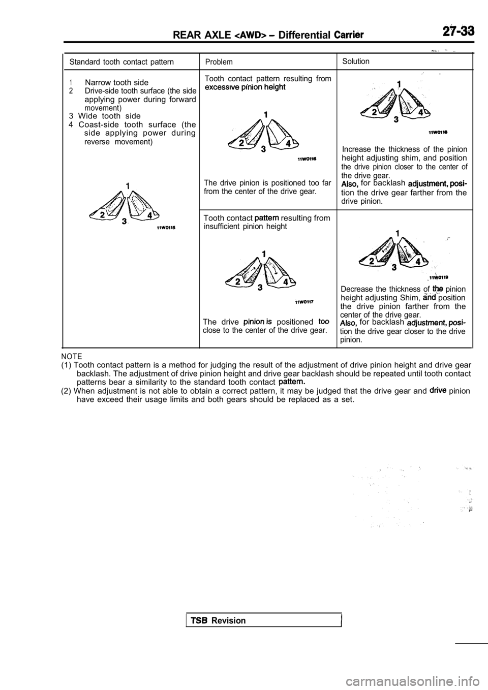
Standard tooth contact patternProblemSolution
.
1Narrow tooth sideTooth contact pattern resulting from. .
2Drive-side tooth surface (the side
applying power during forward
movement)3 Wide tooth side
4 Coast-side tooth surface (the side applying power during
reverse movement)Increase the thickness of the pinion
height adjusting shim, and position
the drive pinion closer to the center of
4
The drive pinion is positioned too far the drive gear.
from the center of the drive gear. for backlash
tion the drive gear farther from the
drive pinion.
Tooth contact resulting from
insufficient pinion height
Decrease the thickness of pinion
height adjusting Shim, position
the drive pinion farther from the
The drive
positioned center of the drive gear.
close to the center of the drive gear. for backlash
tion the drive gear closer to the drive pinion.
NOTE
(1) Tooth contact pattern is a method for judging t he result of the adjustment of drive pinion height and drive gear
backlash. The adjustment of drive pinion height and drive gear backlash should be repeated until tooth contact
patterns bear a similarity to the standard tooth co ntact
(2) When adjustment is not able to obtain a correct pattern, it may be judged that the drive gear and pinion
have exceed their usage limits and both gears shoul d be replaced as a set.
Revision
Page 1568 of 2103
27-34REAR AXLE. Differential
DISASSEMBLY
Drive Gear Tooth Contact Check (Refer to
1820 27 2831
Disassembly steps
l Inspection before disassembly
(Refer to
Differential cover assembly2. Vent plug3. Bearing cap
4. Differential case assembly
5. Side bearing spacer
6. Side bearing outer race
7. Side bearing inner race
Drive gear
9. Lock pin
10. Pinion shaft
11. Pinion gear
12. Pinion washer
13. Side gear differentials
14. Side gear spacer
Differential case16. Limited slip differential case assem-
bly (Refer to
17. Self-locking nut
18. Washer
19. Drive pinion assembly20. Companion flange21. Drive pinion front shim (for preload
adjustment)22. Drive pinion spacer
23. Drive pinion rear bearing inner race
24. Drive pinion rear shim (for pinion
height adjustment)25. Drive pinion
26. Oil seal
27. Drive pinion front bearing inner race
28. Drive pinion front bearing outer race
29. Drive pinion rear bearing outer race
30. Oil seal 31. Gear carrier
.
Page 1569 of 2103
REAR AXLE Differential ‘Carrier
DISASSEMBLY SERVICE POINTS
DIFFERENTIAL CASE ASSEMBLY
Caution
the differential case slowly
fully so that the side bearing race is not
NOTE
Keep the right and left side bearings separate, so that they
do not become mixed at the time of reassembly.
BEARING INNER RACE REMOVAL
Place the nut on top of the differential case, and then use
the special tool to remove the side bearing inner r ace.
NOTE
Attach the prongs of the special tool to the inner ‘race of
the side bearing through the openings in the differential case.
DRIVE GEAR REMOVAL
(1) Make the mating marks to the differential case and the
drive gear.
(2) Loosen the drive gear attaching bolts in diagon al se-
quence to remove the drive gear.
LOCK PIN REMOVAL differential>
NUT REMOVAL
Revision
Page 1570 of 2103
REAR AXLE Differential Carrier
Mating marks
I
(1) Make the mating marks to the drive pinion and companion
.
Caution
Mating marks should not be sur-
faces of companion shaft.“‘
(2) Drive out the drive pinion
spacer and drive pinion ,
. .
PINION REAR BEARING
REMOVAL
O I L
RACE/DRIVE PINION FRONT
OUTER RACE REMOVAL
TSB Revision
REAR BEARING
REMOVAL
INSPECTION
lCheck the companion flange for wear or damage.
lCheck the bearings for wear discoloration.
lCheck the gear carrier for cracks.
lCheck the drive pinion and drive gear or
lCheck the side gears, pinion gears and shaft for
wear or damage.
l Check the side gear
for damage
Page 1571 of 2103

AXLE Differential’
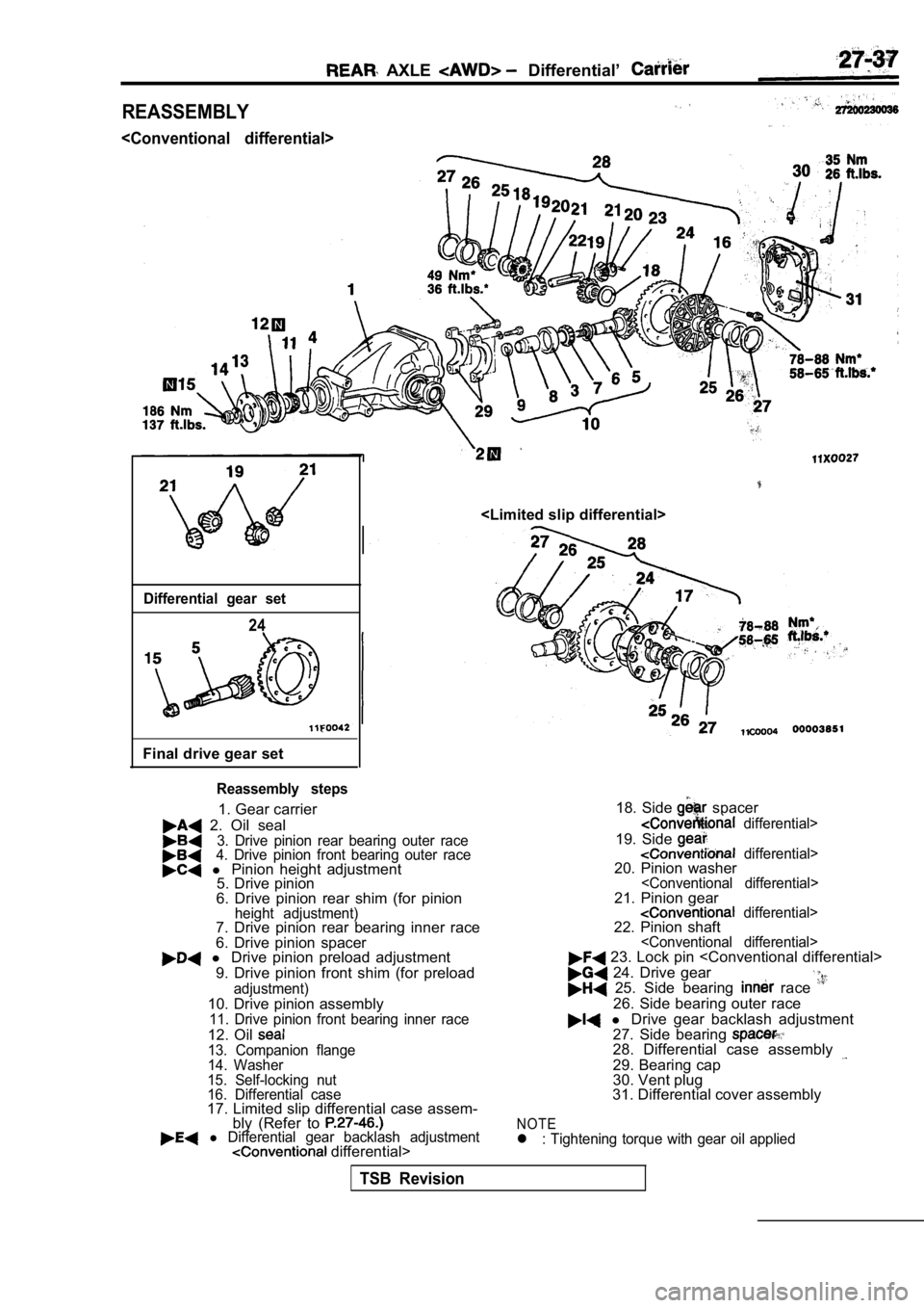
REASSEMBLY
Differential gear set
24
Final drive gear set
Reassembly steps
1. Gear carrier
2. Oil seal3. Drive pinion rear bearing outer race4. Drive pinion front bearing outer race l Pinion height adjustment
5. Drive pinion
6. Drive pinion rear shim (for pinion
height adjustment)7. Drive pinion rear bearing inner race
6. Drive pinion spacer
l Drive pinion preload adjustment
9. Drive pinion front shim (for preload
adjustment)10. Drive pinion assembly11. Drive pinion front bearing inner race
12. Oil 13. Companion flange
14. Washer
15. Self-locking nut
16. Differential case
17. Limited slip differential case assem- bly (Refer to
l Differential gear backlash adjustment differential> 18. Side
spacer
differential>
19. Side differential>20. Pinion washer21. Pinion gear differential>22. Pinion shaft 23. Lock pin
24. Drive gear 25. Side bearing race
26. Side bearing outer race
l
Drive gear backlash adjustment
27. Side bearing
28. Differential case assembly
29. Bearing cap
30. Vent plug
31. Differential cover assembly
NOTEl : Tightening torque with gear oil applied
TSB Revision
Page 1572 of 2103
2-3 mm in.)
Adhesive: Locking No.
or equivalent ,
TSB Revision
Page 1573 of 2103

REARAXLE Differential
Front bearingRear bearing1
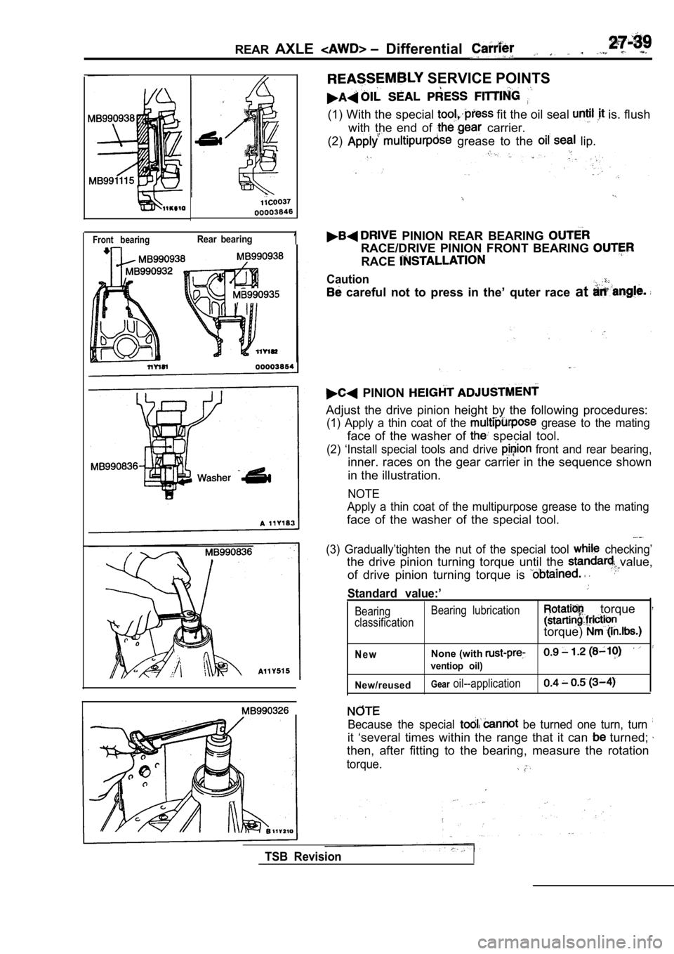
SERVICE POINTS
(1) With the special fit the oil seal is. flush
with the end of
carrier.
(2)
grease to the lip.
PINION REAR BEARING
RACE/DRIVE PINION FRONT BEARING
RACE
Caution
careful not to press in the’ quter race at
PINION
Adjust the drive pinion height by the following pro cedures:
(1) Apply a thin coat of the grease to the mating
face of the washer of special tool.
(2) ‘Install special tools and drive front and rear bearing,
inner. races on the gear carrier in the sequence sh own
in the illustration.
NOTE
Apply a thin coat of the multipurpose grease to the mating
face of the washer of the special tool.
(3) Gradually’tighten the nut of the special tool checking’
the drive pinion turning torque until the value,
of drive pinion turning torque is
Standard value:’
Bearing Bearing lubrication
classification torque
torque)
N e wNone (with
ventiop oil)
New/reused
Gearoil--application
TSB Revision
Because the special be turned one turn, turn
it ‘several times within the range that it can turned;
then, after fitting to the bearing, measure the rot ation
torque.
Page 1574 of 2103

REAR AXLE Differential Carrier
Fe gauge
Bearing cap
Al
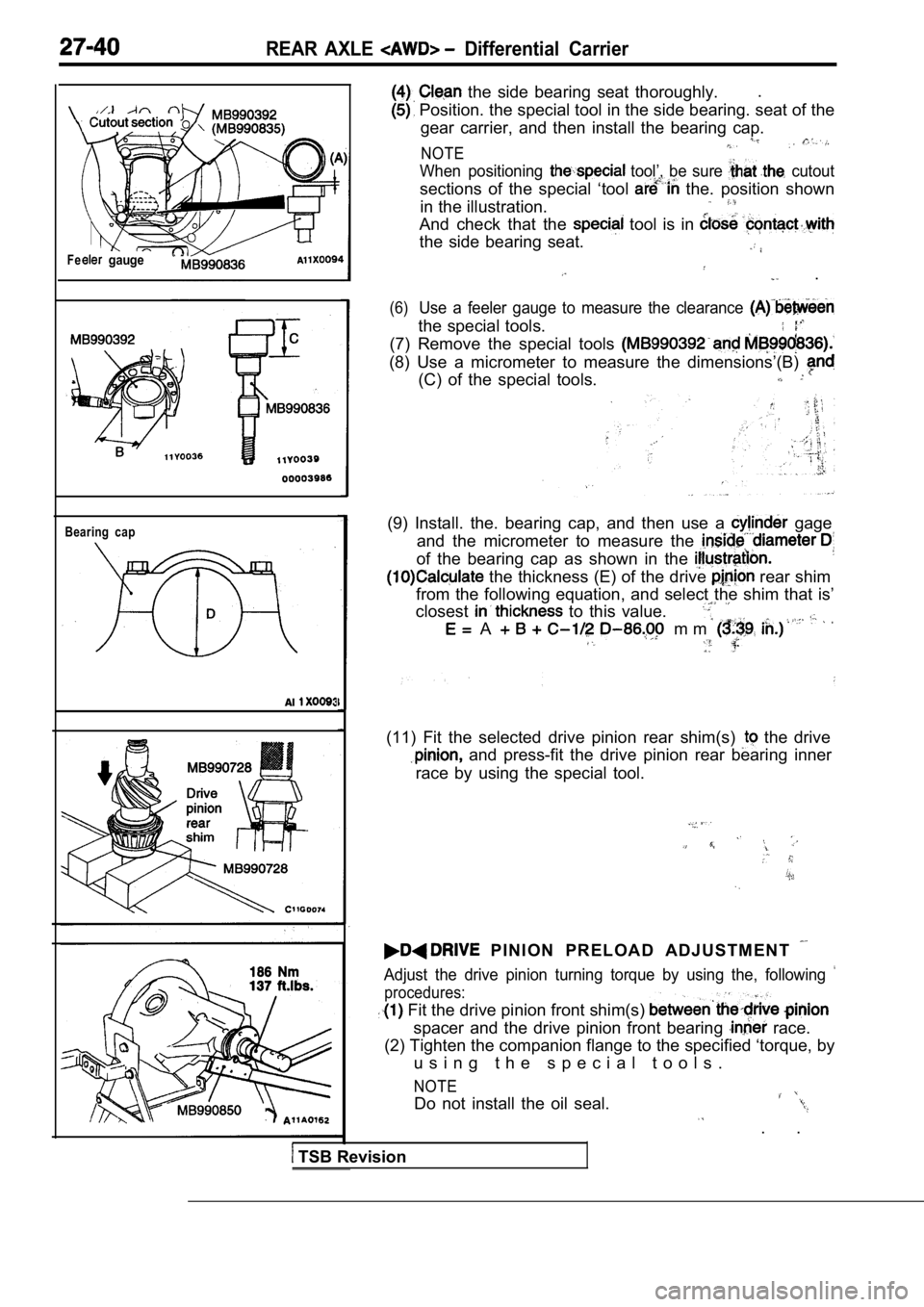
the side bearing seat thoroughly..
Position. the special tool in the side bearing. se
at of the
gear carrier, and then install the bearing cap.
NOTE
When positioning tool’, be sure cutout
sections of the special ‘tool the. position shown
in the illustration.
And check that the tool is in
the side bearing seat.
.
(6)Use a feeler gauge to measure the clearance
the special tools.
(7) Remove the special tools
(8) Use a micrometer to measure the dimensions’(B)
(C) of the special tools.
(9) Install. the. bearing cap, and then use a gage
and the micrometer to measure the
of the bearing cap as shown in the
the thickness (E) of the drive rear shim
from the following equation, and select the shim th at is’
closest
to this value.
A m m
(11) Fit the selected drive pinion rear shim(s) the drive
and press-fit the drive pinion rear bearing inner
race by using the special tool.
P I N I O N P R E L O A D A D J U S T M E N T
Adjust the drive pinion turning torque by using the , following
procedures:
Fit the drive pinion front shim(s)
spacer and the drive pinion front bearing race.
(2) Tighten the companion flange to the specified ‘ torque, by
u s i n g t h e s p e c i a l t o o l s .
NOTE
Do not install the oil seal.
. .
TSB Revision