Page 1575 of 2103

REAR AXLE Differential Carrier
or
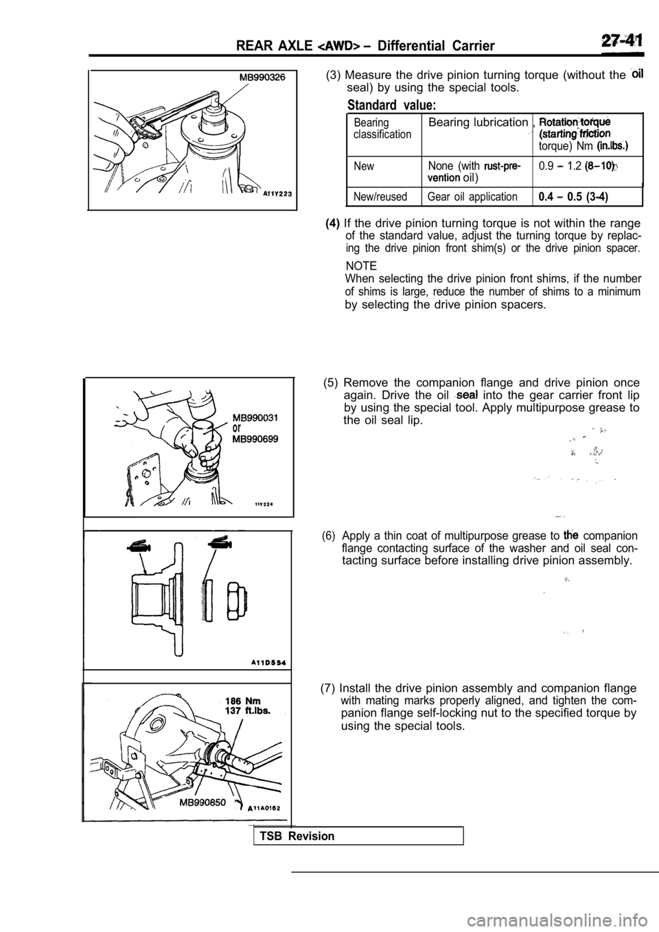
(3) Measure the drive pinion turning torque (without the
seal) by using the special tools.
Standard value:
BearingBearing lubrication ,
classification
torque) Nm
NewNone (with 0.9 1.2
oil)
New/reused Gear oil application0.4 0.5 (3-4)
(4)If the drive pinion turning torque is not within th e range
of the standard value, adjust the turning torque by replac-
ing the drive pinion front shim(s) or the drive pinion spacer.
NOTE
When selecting the drive pinion front shims, if the number
of shims is large, reduce the number of shims to a minimum
by selecting the drive pinion spacers.
(5) Remove the companion flange and drive pinion on ce
again. Drive the oil
into the gear carrier front lip
by using the special tool. Apply multipurpose greas e to
the oil seal lip.
(6)Apply a thin coat of multipurpose grease to companion
flange contacting surface of the washer and oil sea l con-
tacting surface before installing drive pinion assembly.
(7) Install the drive pinion assembly and companion flange
with mating marks properly aligned, and tighten the com-
panion flange self-locking nut to the specified torque by
using the special tools.
TSB Revision
Page 1576 of 2103

REAR AXLE Differential Carrier
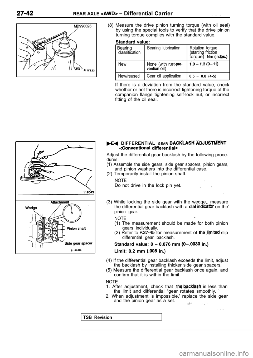
(8) Measure the drive pinion turning torque (with oil seal)
by using the special tools to verify that the drive pinion
turning torque complies with the standard value.
Standard value:
BearingBearing lubrication Rotation torque
classification (starting friction
torque)
NewNone (with
oil)
New/reusedGear oil application0.5 0.8 (4-5)
there is a deviation from the standard value, chec
k
whether or not there is incorrect tightening torque of the
companion flange tightening self-lock nut, or incor rect
fitting of the oil seal.
DIFFERENTIAL GEAR
differential>
Adjust the differential gear backlash by the follow ing proce-
dures:
(1) Assemble the side gears, side gear spacers, pin ion gears,
and pinion washers into the differential case.
(2) Temporarily install the pinion shaft.
NOTE,
Do not drive in the lock pin yet.,
(3) While locking the side gear with the wedge,. me asure
the differential gear backlash with a
on the’
pinion gear.
NOTE
(1) The measurement should be made for both pinion
gears individually.
(2) Refer to for measurement of slip
differential gear backlash.
Standard value: 0 0.076 mm in.)
Limit: 0.2 mm
in.)
(4) If the differential gear backlash exceeds the l imit, adjust
the backlash by installing thicker side gear spacer s.
(5) Measure the differential gear backlash once aga in, and
confirm that it is within the limit.
NOTE
1. After adjustment, check that is less than
the limit and differential “gear rotates smoothly.
2. When adjustment is impossible,’ replace the side gear
and the pinion gear as a set.
TSB Revision
Page 1577 of 2103

REAR AXLE Differential Carrier
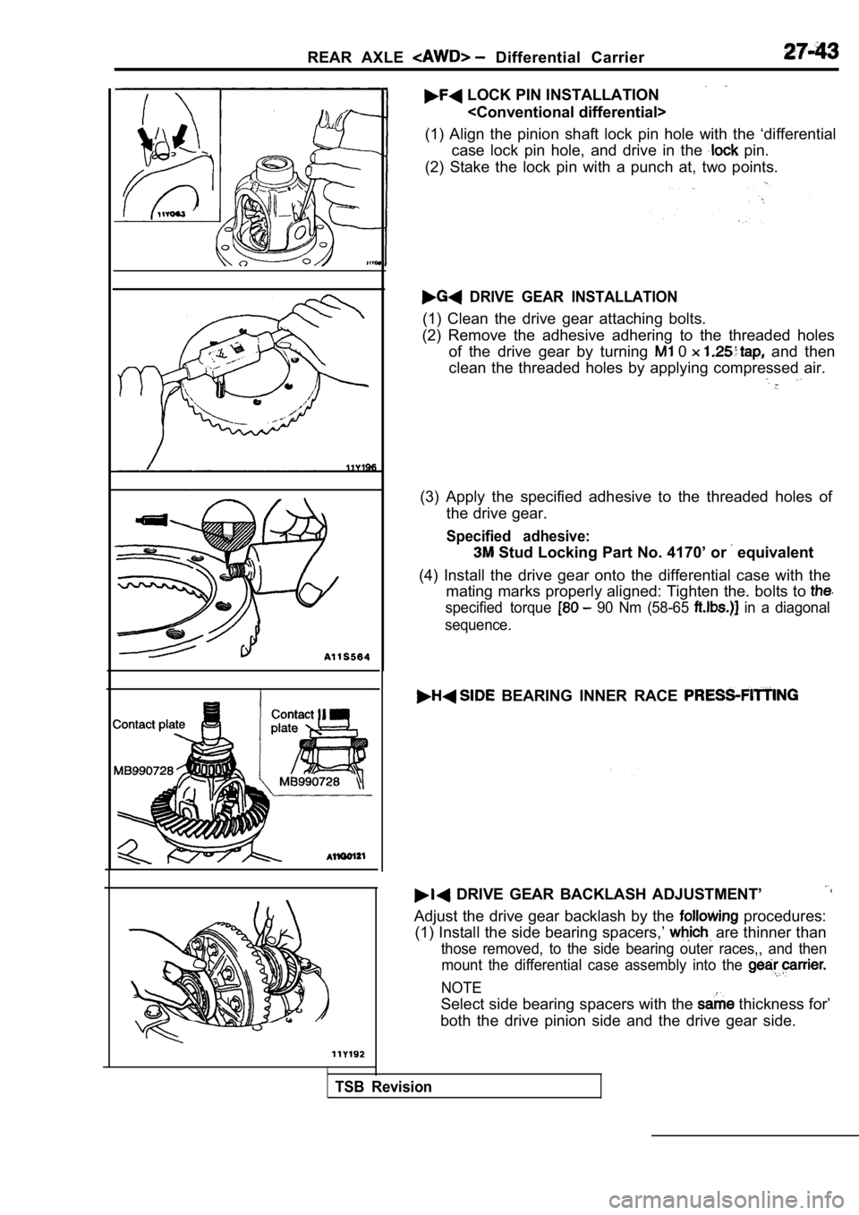
LOCK PIN INSTALLATION
(1) Align the pinion shaft lock pin hole with the ‘ differential
case lock pin hole, and drive in the
pin.
(2) Stake the lock pin with a punch at, two points.
DRIVE GEAR INSTALLATION
(1) Clean the drive gear attaching bolts.
(2) Remove the adhesive adhering to the threaded ho les
of the drive gear by turning
0 and then
clean the threaded holes by applying compressed air .
(3) Apply the specified adhesive to the threaded holes of
the drive gear.
Specified adhesive:
Stud Locking Part No. 4170’ or equivalent
(4) Install the drive gear onto the differential ca se with the
mating marks properly aligned: Tighten the. bolts t o
specified torque 90 Nm (58-65 in a diagonal
sequence.
BEARING INNER RACE .
DRIVE GEAR BACKLASH ADJUSTMENT’
Adjust the drive gear backlash by the procedures:
(1) Install the side bearing spacers,’
are thinner than
those removed, to the side bearing outer races,, an d then
mount the differential case assembly into the
NOTE
Select side bearing spacers with the thickness for’
both the drive pinion side and the drive gear side.
TSB Revision
Page 1578 of 2103
REAR AXLE Differential
2 0.05 mm in.) Thickness of the spacer on
one side
(2) Push the differential case to ‘one and measure the
clearance between the gear carrier and the bearing.
(3) Measure the thickness the side bearing on
one side, select two pairs of spacers which corresp ond
to that thickness plus one half of the clearance pl us 0.05
mm, and then install one pair each to the drive pin ion
side and the drive gear side.
(4) Install side bearing spacers and differential case as-
sembly, as shown in the illustration;’
the
, .
,.
(5) Tap the side bearing spacers with a brass bar t o fit them
to the side bearing outer race.
(6)Align the mating marks on the gear carrier and the bearing’:
cap, and then tighten the bearing cap.
TSB Revision
Page 1579 of 2103
REAR AXLE Differential
If backlash is too small
spacer spacer
If backlash is too large
With the drive in place, measure’ the
gear backlash with a dial the drive gear.
Measure at four points or more on
of the drive gear.Standard value: 0.11
0.16 mm In.)
(8) Change the side bearing spacers as illustrated, and then
adjust the drive gear backlash between the drive ge ar
and the drive pinion.
NOTE
When increasing the number of bearing spacers,
use the same number for each, and as few
(9) Check the drive gear and drive pinion for tooth contact;
If poor contact is evident, make adjustment. (Refer to
(lO)Measure the drive gear at the shoulder on the
reverse side of the drive gear.
L i m i t : 0 . 0 5 m m
(11) If the gear exceeds limit, reinstall by
changing the phase of the drive gear and differenti al case,
and remeasure.
TSB Revision
Page 1580 of 2103
REAR AXLE Assembly, . . .
Feeler
Feelergauge
gear (R.H.) washer .
A
INSPECTION BEFORE
DIFFERENTIAL
(1) Hold the limited a
the differential side
Caution
When the limited slip in
vice, do not tighten
(2)Install two 0.03 ih.)
between the differential case
Caution
Do not insert the feeler
i n t h e d i f f e r e n t i a l
.
. .
I the special in the splined of the
tial’ side gear (R.H.) and make the side gear
(R.H.) turns.
the feeler gauges with in.) feeler:
“gauges..
the special tool in the
gear (R.H.) and make gear’
(R.H.) does not turn.,,
Standard value:
mm in.)
NOTE
The differential gear backlash is normal if the side gear
clearance in the direction of thrust is within the standard
value.
(6) If the side gear clearance in the direction of thrust
not within the standard value, remove the differential case
(A) and adjust by means of thrust washer (L.H.).
Thrust washer (L.H.)
Part No.Thickness mm (in.)
0.8
0.9
1
1.1
1.15
1.2
1.25
1.3
I1.35
1.4
1.5
Revision
Page 1581 of 2103
REAR AXLE LSD Case Assembly
Thrust washer (R.H.) [Reference]
Part No.Thickness mm (in.)
0.8
NOTE
The thrust washers (L.H.) are a
one appropriate thrust washer from 11 wash-,ers.
DISASSEMBLY AND REASSEMBLY27300140011
Disassembly steps
l Inspection before disassembly, t o
Differential case (A) 3. Thrust washer (L.H.)
4. Viscous coupling (with differential
side gear: L.H.)
5. Pinion mate washer
6. Differential pinion mate
7. Differential pinion shaft
8. Differential side gear
9. Thrust washer (R.H.) 10. Differential case (B)
NOTELSD: Limited slip differential
DISASSEMBLY SERVICE POINT
WASHER (R.H.)
The thrust washer (L.H.) differs from the thrustwasher (R.H.)
in thickness.
Keep them separately from each other for reference in assem-
bly.
TSBRevision
Page 1582 of 2103

REAR AXLE LSD Case Assembly
l - - c a s e ( B )
Pinion mate
washer
TSB
REASSEMBLY SERVICE POINTS
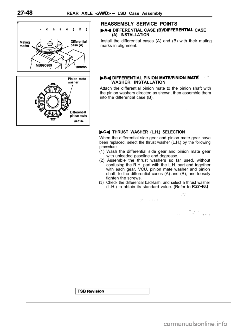
DIFFERENTIAL CASE CASE
(A) INSTALLATION
Install the differential cases (A) and (B) with the ir mating
marks in alignment.
DIFFERENTIAL PINION
WASHER INSTALLATION
Attach the differential pinion mate to the pinion s haft with
the pinion washers directed as shown, then assemble them
into the differential case (B).
THRUST WASHER (L.H.) SELECTION
When the differential side gear and pinion mate gea r have
been replaced, select the thrust washer (L.H.) by the following
procedure.
(1) Wash the differential side gear and pinion mate gear
with unleaded gasoline and degrease.
(2) Assemble the thrust washers so far used, withou t
confusing the R.H. part with the L.H. part and toge ther
with each gear, VCU, pinion mate washer and pinion
shaft, to the differential cases (A) and (B), and l oosely
tighten the screws.
(3)Check the differential backlash, and select a thrus t washer
(L.H.) to obtain its standard value. (Refer to