1990 MITSUBISHI SPYDER oil temperature
[x] Cancel search: oil temperaturePage 1782 of 2103
STEERING On-vehicle Service
S T E E R I N G
1. the vehicle stopped on a paved surface, turn
the steering wheel to the straight ahead ‘position.
2.Start the engine and set to 1,000
Caution
After checking the engine rpm., there
a
to the standard idling rpm.
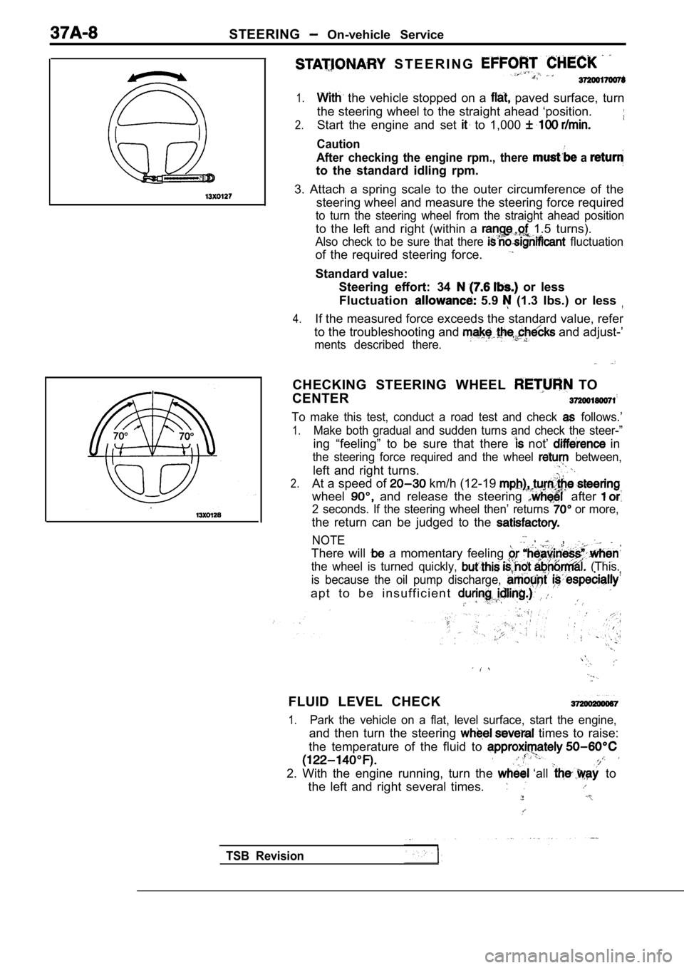
3. Attach a spring scale to the outer circumference of the
steering wheel and measure the steering force requi red
to turn the steering wheel from the straight ahead position
to the left and right (within a 1.5 turns).
Also check to be sure that there fluctuation
of the required steering force.
Standard value:
Steering effort: 34
or less
Fluctuation
5.9 (1.3 Ibs.) or less
4.If the measured force exceeds the standard value, r efer
to the troubleshooting and
and adjust-’
ments described there.
CHECKING STEERING WHEEL TO
CENTER
To make this test, conduct a road test and check follows.’
1.Make both gradual and sudden turns and check the st eer-”
ing “feeling” to be sure that there not’ in
the steering force required and the wheel between,
left and right turns.
2.At a speed of km/h (12-19
wheel and release the steering after
2 seconds. If the steering wheel then’ returns or more,
the return can be judged to the
NOTE ,
There will a momentary feeling
the wheel is turned quickly, (This.
is because the oil pump discharge,
a p t t o b e i n s u f f i c i e n t
FLUID LEVEL CHECK
1.Park the vehicle on a flat, level surface, start th e engine,
and then turn the steering times to raise:
the temperature of the fluid to
2. With the engine running, turn the ‘all to
the left and right several times.
TSB Revision
Page 2030 of 2103
SRS Air Bag Modules and Clock Spring
AIR BAG MODULES AND CLOCK SPRING52400240022
Caution
1.Never attempt to disassemble or repair the
air bag module or clock spring. If faulty,
replace it.
2. Do not drop the air bag module or clockspring or allow contact with water, grease
or oil. Replace it if a dent, cracks,
deformation or rust are detected.
3. The air bag modules should be stored on
a flat surface and placed so that the pad
surface is facing upward. Do not place anything on top of
bag
modules.
4.
Do not expose the air module to
temperature over
5.After deployment of an air bag, replace the
clock spring.
6. Wear gloves and safety goggles
handling an air bag that has
7.An undeployed air bag module should only
be disposed of in accordance with the
specified procedures. (Refer to
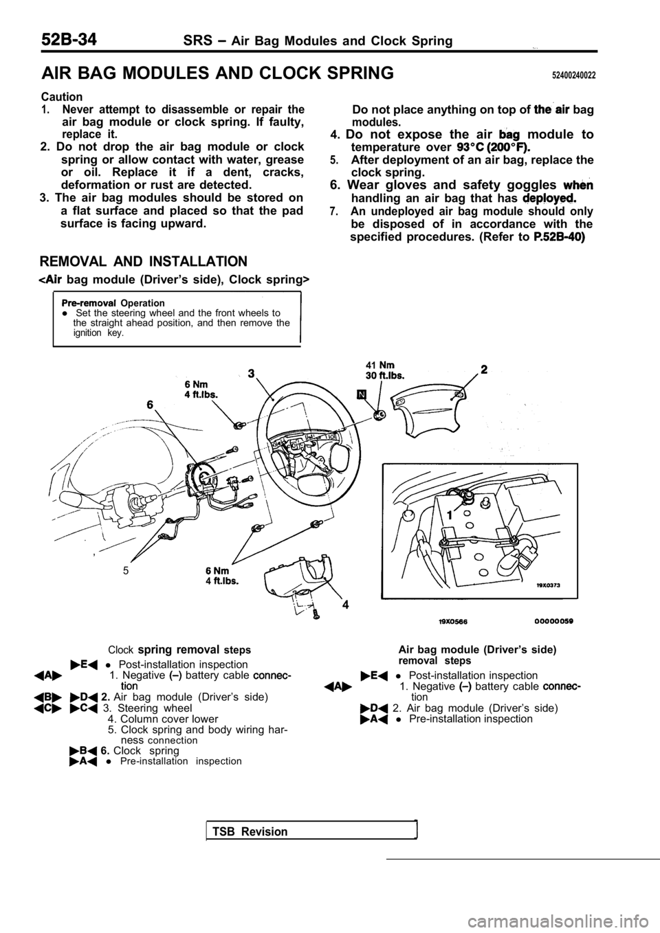
REMOVAL AND INSTALLATION
bag module (Driver’s side), Clock spring>
Operationl Set the steering wheel and the front wheels to
the straight ahead position, and then remove the
ignition key.
41
1. Negative battery cable l Post-installation inspection
2. Air bag module (Driver’s side) 1. Negative battery cable tion
3. Steering wheel
4. Column cover lower 2. Air bag module (Driver’s side)
5. Clock spring and body wiring har- l Pre-installation inspection
ness connection
6. Clock spring l Pre-installation inspection
TSB Revision
,
54
4
Clockspring removal steps
l Post-installation inspection Air bag module (Driver’s side)removal steps
Page 2044 of 2103
55-4HEATER, AIR
AND VENTILATION General Information
SAFETY PRECAUTIONS
Because R-l refrigerant is a, hydrofluorocarbon
(HFC) which contains hydrogen atoms in place of
chlorine atoms, it will not cause damage to the
ozone layer.
Ozone filters out harmful radiation from the sun.
To assist in protecting the ozone layer, Chrysler
Corporation recommends an R-l refrigerant re-
cycling device.
Refrigerant R-l is transparent and colorless
in both the liquid and vapor state. Since it has
a boiling point of at atmospher-
ic pressure, it will be a vapor at all normal tempe ra-
tures and pressures. The vapor is heavier than
air, non-flammable, and nonexplosive. The follow-
ing precautions must be observed when handling
R-l
Caution
Wear safety goggles when servicing the refrig-
eration system.
R-l evaporates so rapidly at normal atmospher-
ic pressures and temperatures that it tends to free ze
anything it contacts. For this reason, extreme care
must be taken to prevent any liquid refrigerant fro m
contacting the skin and especially the eyes. Always
wear safety goggles when servicing the refrigeratio n
part of the A/C system. Keep a bottle of sterile
mineral oil handy when working on the refrigeration
system. Should any liquid refrigerant get into the
eyes, use a few drops of mineral oil to wash them
out. is rapidly absorbed by the oil. Next
splash the eyes with plenty of cool water. Call your
doctor immediately even though irritation has
ceased after treatment.
Caution
Do not heat above
In most instances, moderate heat is required to
bring the pressure of the refrigerant inits
above the pressure of the system when charging
or adding refrigerant.
A bucket or large pan of hot water
over
is all the heat required for this purpose.
Do not heat the refrigerant container with a blow
torch or any other means that would raise tempera-
ture and pressure above this temperature. Do not
weld or steam clean on or near the system compo-
nents or refrigerant lines.
Caution
Keep
containers upright when charging
the system.
When adding into the refrigeration system
keep the supply tank or cans in an upright
position.
If the refrigerant container is on its or upside
down, liquid refrigerant will enter the
damage the compressor.
Caution
1.A leak detector designed
be used to check refrigerant gas
2.Do not allow liquid refrigerant to
metal.
Refrigerant will tarnish bright metal and chrome
surfaces, and in combination with moisture can
severely corrode all metal surfaces.
TSB Revision
Page 2045 of 2103

HEATER, AIR Service
AND VENTILATION Special Tools
SERVICE SPECIFICATIONS
IStandard value ‘I
speed E n g i n e ( T u r b o ) a n d
EngineII
Engine (Non-turbo)I
up speed
Resistor (for blower motor) LO
100 in Neutral
1.83
MHI 0.31
Revolution pick up sensor standard resistance
Engine (Non-turbo)>
185
[when ambient temperature is
Refrigerant temperature switch ON (continuity) tempe rature
Engine (Turbo) and
Engine>OFF (no continuity) temperature
Approx. or less
Approx. or more
(until the temperature drops to approx.
when OFF)
Air gap (Magnetic clutch) mm (in.)
Engine (Turbo) and
Engine
Engine (Non-turbo)I
LUBRICANTS
ItemsSpecified lubricants Quantity
Each connection of refrigerant line ND-OIL 8 Engine (Non-turbo)>, SUN PAG 56 As required
Engine (Turbo) and Engine>
Lip seal of the compressor ND-OIL 8
Engine (Non-turbo)>As required
Compressor refrigerant unit lubricant SUN PAG 56
lubricant
Engine (Turbo) and Engine>
ND-OIL 8
Engine (Non-turbo)>
SPECIAL TOOLS
ToolTool number and nameSupersession Application
367Armature mounting nut of com-
e S p e c i a l s p a n n e r removal and installation
Engine (Turbo) and
Engine>
386
Pin
TSB Revision
Page 2046 of 2103

HEATER, AIR
AND VENTILATION Troubleshooting
TROUBLESHOOTING
PROCEDURES
Trouble
symptom
When the ignitior
switch is “ON”,
the
does not
operate.
conditioning
does not
when
he air outlet
knob is
noved to the
or
position. Problem cause
compressor clutch relay
is defective
Magnetic clutch is defective
Refrigerant leak or overfilling
of refrigerant
Dual pressure switch is defec-
tive
A/C switch is defective Blower switch is defective
Fin
sensor is defective
Refrigerant temperature switch
is defective
Engine (Tur-
bo) and
Engine>
Automatic compressor-ECM
is defective
Revolution pick up sensor is
defective
Engine (Non-turbo)>
A/C compressor relay is de-
fective
1
Dual pressure switch is defec-
tive
Defroster switch is defective
TSB Revision
Magnetic clutch is defective
Refrigerant leak or overfilling
of refrigerant Remedy
Reference ReferencepagepageEngine
Engine(Non-turbo) (Turbo) Engine
Replace A/C compressor clutch 55-1855-18
relay
Replace the armature plate, rotor55-34
or clutch coil
Replenish the refrigerant, repair
0
the leak or take out some of therefrigerant
Replace the dual pressure switch 55-45
Replace the A/C switch 55-2355-23
Replace the blower switch55-22 55-22
Replace the fin sensor
Replace the refrigerant tempera-
ture switch
Replace the automatic
Replace the revolution pick up
sensor
55-26
Replace A/C compressor clutch55-18
relay
Replace the armature plate, rotor55-34
or clutch coil
Replenish the refrigerant, repair
the leak or take out some of the
refrigerant
Replace the dual pressure switch55-45
the defroster switch55-22 55-22
the blower switch55-225 5 - 2 2
temperature Replace the refrigerant tempera-
is defective
ture switch
compressor-ECU isReplace the automatic 55-26
sor-ECU
pick up sensor is
Replace the revolution pick up
sensor Engine
Page 2053 of 2103
HEATER, AIR
AND VENTILATION On-vehicle Service
USING REFRIGERANT RECOVERY
RECYCLING UNIT
the refrigerant recovery and recycling refill the
refrigerant.
NOTE
Refer to that Refrigerant Recovery and Recycling Unit Instruc-
tion Manual for operation of the unit.
DISCHARGING SYSTEM
Use the refrigerant recovery unit to discharge refrigerant gas
from the system.
NOTE
Refer to that Refrigerant Recovery and Recycling Un it Instruc-
tion Manual for operation of the unit.
REFILLING OFOIL IN THE A/C SYSTEM
Too little oil will provide inadequate compressor l ubrication
and cause a compressor failure. Too much oil will i ncrease
discharge air temperature.
When a compressor is installed at the factory, it c ontains
170
(5.7 Engine (Turbo) and
100 (3.4 Engine (Non-turbo)> of refrigerant
oil.
the A/C is in operation, the oil is carried
through the entire system by the refrigerant. Some of this
oil will be trapped and retained in various parts of the system.
When the following system components are changed, i t is
necessary to add oil to the system to replace the o il being
removed with the component.
Engine (Turbo) and Engine>
Compressor oil: SUN PAG 56
Quantity
Evaporator: 60 (2.03
Condenser: 15
Suction hose: 10
Receiver: 10
Engine (Non-turbo)>
Compressor oil: ND-OIL 8
Q u a n t i t y Evaporator: 40
(1.35
Condenser: 40 (1.35
Suction hose: 10
Receiver: 16
Revision
Page 2056 of 2103
6HEATER, AIR
AND VENTILATION On-vehicle Service
COMPRESSOR NOISE CHECK
You must first know the conditions when the noise occurs. These conditions are: weather, vehicle speed,
in gear or neutral, engine temperature or any other special conditions.
Noises that develop during A/C operation can often be misleading. For example: what sounds like a
failed front bearing or connecting rod, may be caus ed by loose bolts, nuts, mounting brackets, or a
loose clutch assembly. Verify accessory drive belt tension (power steering or generator).
Improper accessory drive belt tension can cause a m isleading noise when the compressor is engaged
and little or no noise when the compressor is disen gaged.
Drive belts are speed-sensitive. That is, at differ ent engine speeds, and depending upon belt tension,
belts can develop unusual noises that are often mis taken for mechanical problems within the compressor .
ADJUSTMENT
1. Select a quiet area for testing. Duplicate conditions as much as possible. Switch compressor on
and off several times to clearly identify compresso r noise. To duplicate high ambient
head pressure), restrict air flow through condenser . Install manifold gauge set sure discharge
pressure doesn’t exceed 2,070 (300 psi).
2. Tighten all compressor mounting bolts, clutch mo unting bolt, and compressor drive belt. Check to
assure clutch coil is tight (no rotation or wobble) .
3. Check refrigerant hoses for rubbing or interfere nce that can cause unusual noises.
4. Check refrigerant charge. (Refer to
5. Recheck compressor noise as in Step 1.
6. If noise still exists, loosen compressor mountin g bolts and retorque. Repeat Step 1.
7. If noise continues, replace compressor and repea t Step 1.
Revision
Page 2070 of 2103
HEATER, AIR
AND VENTILATION Cooling Unit
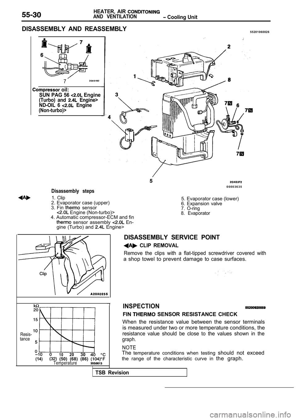
DISASSEMBLY AND REASSEMBLY5 5 2 0 1 0 6 0 0 2 6
7
oil:
SUN PAG 56
Engine
(Turbo) and Engine>
ND-OIL 6
Engine
(Non-turbo)>
0 0 0 0 3 6 3 5
Disassembly steps
1. Clip
2. Evaporator case (upper)
3. Fin sensor Engine (Non-turbo)>
4. Automatic compressor-ECM and fin
sensor assembly En-
gine (Turbo) and Engine> 5. Evaporator case (lower)
6. Expansion valve
7. O-ring
8. Evaporator
Resis-
tance
1 02030 40(14) (50) (68) (86) Temperature
INSPECTION
FIN SENSOR RESISTANCE CHECK
When the resistance value between the sensor termin als
is measured under two or more temperature condition s, the
resistance value should be close to the values show n in the
graph.
NOTE
Thetemperature conditions when testing should not exceed
the range of the characteristic curve in the graph.
TSB Revision
DISASSEMBLY SERVICE POINT
CLIP REMOVAL
Remove the clips with a flat-tipped screwdriver cov ered with
a shop towel to prevent damage to case surfaces.