Page 1177 of 2103

AUTOMATIC TRANSAXLE
ENGINE (NON-TURBO)> On-vehicle .
FLUID LEAKAGE-TORQUE CONVERTER
HOUSING AREA CHECK
(1) Check for source of leakage.Since fluid leakage at or around the torque convert er
area may originate from an engine oil leak, the area should
be examined closely, Factory fill fluid is dyed red and,
therefore, can be distinguished from engine oil.
(2) Before removing the transaxle, perform the foll owing
checks:
When leakage is determined to originate from the tr ans-
axle, check fluid level before removal of the transaxle
and torque converter.
High oil level can result in oil leakage out the vent in
the manual shaft. If the fluid level is high, adjust to
proper level.
After fluid is at the proper level, check for leakage. If
a leak
perform the following operation on the
to determine if it is the torque converter or tran saxle
that is, leaking.
TORQUE CONVERTER LEAKAGE
Possible sources of torque converter leakage are:
(2) Torque converter weld leaks at the out side (pe ripheral)
weld. Torque converter hub weld.
(3) Hub
inside and not visible. Do not attempt to
repair.
Replace torque converter.
If the torque converter must be replaced, refer to Torque
Converter Clutch Break-in Procedure in this section . This
procedure’ will reset the transaxle control module break-in
status. Failure to perform this procedure may cause transaxle
shutter.
Clutch
HYDRAULIC PRESSURE TESTS
Pressure testing is a very important step in the diagnostic
procedure. These tests usually reveal the cause of most
transaxle problems.
Before performing pressure tests, be certain that fluid level
and condition, and shift cable adjustments have bee n checked
and approved.Fluid must be at operating temperature
(150 to
1. Install an engine tachometer.
2.Raise vehicle on hoist which allows front wheels to
turn,
and position tachometer so it can be read.
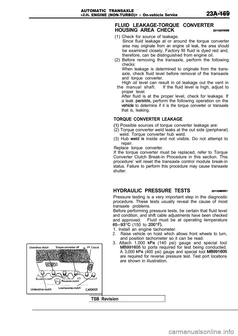
3. Attach 1,000
(140 psi) gauge and special tool
to ports required for test being conducted.
A 3,000 (400 psi) gauge and special tool
are required for reverse pressure test. Test port l ocations
are shown in illustration.
TSB Revision
Page 1221 of 2103
39.
40.
41.
44:
45.
46.
47.
50.
51.
52. 53.
Pulse generatorSpring washerControl lever
ClampPark/neutral position switch
Oil temperature sensor
End clutch cover
O-ring
BearingEnd clutch
Thrust washer
End clutch hub
Thrust bearing
End clutch shaftBearing retainer
Snap ring Lock plate
54. Idler gear shaft55. Bearing inner race’
56. Idler gear
57. Bearing inner race
58. Spacer
59. Snap ring .60. servo switch
61. servo piston
62. Spring
63. Anchor rod64. flange
65. Transfer shaft
66. Outer race
67. Gasket . .
,
68. O-ring
6 9 . V a l v e b o d y
TSB Revision
Page 1223 of 2103
A U T O M A T I C T R A N S A X L EOVERHAUL Transaxle
the snap ring and remove
switch.
(8) Remove the oil pan and oil gasket.
(9) Remove the oil filter.
the oil temperature sensor bracket. mounting
bolts’and remove the oil temperature sensor from brack-
et. Using a screwdriver, push out the rubber plug,
from inside the case, and remove the oil temperatur e
sensor from the case..
(11) With their catches pressed down, force the har
ness grom-
met and connector into the transaxle case:,
TSB Revision
Page 1304 of 2103
AUTOMATIC TRANSAXLE
OVERHAUL,
(8) Remove the oil filter from the valve body.
.
,
(9) Remove the 10 valvebody mounting
the oil temperature sensor holder and
oil temperature sensor clamp,
,
the finger of the solenoid valve harness grommet,,
push the grommet into and remove the valve
body assembly.
out the oil temperature sensor.
the parking roller
I-
*
the set screw of the manual shaft and’
remove the manual control shaft
the detent plate.
--. .
TSB Revision
Page 1325 of 2103
AUTOMATIC
OVERHAUL Transaxle
A
the oil temperature sensor into the
,
an O-ring in the O-ring groove at the top of ‘the
valve body assembly.
the solenoid valve harness grommet with
valve connector transaxle
case hole from the inside,
the solenoid valve harness the case
hole.
the knock pin of the valve body
keeping the detent plate pin in the manual groove.
Temporarily install the valve body,
the oil tempera-
ture sensor and holder; then tighten the
to the specified torque.
A 1 8
bolt: 40 mm (1.58 in.)
body assembly mounting 11
Caution
Firmly fasten the and temperature
sensor harness at the shown positions.
Especially, be sure to route the pressure
(PCSV) harness, which is separated from
other harness, as shown in the diagram and
the harness. Failure to fasten it may result in con tact
with the detent plate or parking rod.
TSB Revision
Page 1330 of 2103
AUTOMATIC TRANSAXLE
OVERHAUL
Transaxle
3218
38 78
Nm
9 Nm 7
41
24 Nm
46
11 Nm8I
- -
42 during reassembly.
44. Oil temperature 45. Oil filter”
46: Valve body assembly
47. Manual control lever
48.
position switch (PNPswitch) End clutch’ shaft 50. Bearing retainer
51. Thrust bearing 52. End clutch 53. Thrust washer
54. End clutch assembly:
55. O-ring
31.Oil dipstick
32. Oil filler tube
33.Snap ring34. servo switch35.Snap ring
36. servo piston37.Spring
38.Anchor rod
39.Detent plate40. Manual control shaft 41. Parking roller support
42.Oil pan43.Gasket
TSB Revision
Page 1332 of 2103
AUTOMATIC TRANSAXLE
OVERHAUL -Transaxle
(8) Remove the oil filter from the
(9) Remove the 10 valve body mounting bolts.
the oil temperature sensor holder and remove
the oil temperature sensor harness from the clamp.
the finger of the solenoid valve grommet,
push the grommet into the case and ‘remove the valv e
body assembly.
out the oil temperature sensor.
the parking roller support.
the set screw of the control shaft and
remove the manual control shaft assembly.
the detent plate.
TSB Revision
Page 1356 of 2103

AUTOMATIC TRANSAXLE
OVERHAUL -Transaxle
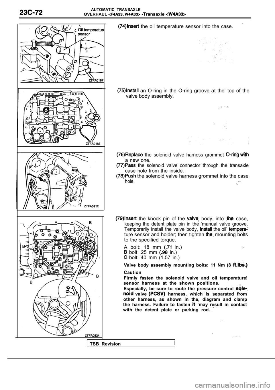
the oil temperature sensor into the case.
an O-ring in the O-ring groove at the’ top of the
valve body assembly.
the solenoid valve harness grommet
a new one.
the solenoid valve connector through the transaxle
case hole from the inside.
the solenoid valve harness grommet into the case
hole.
the knock pin of the body, into case,
keeping the detent plate pin in the ‘manual valve g roove.
Temporarily install the valve body,
the oil’
ture sensor and holder; then tighten mounting bolts
to the specified torque.
A bolt: 18 mm
in.)
bolt: 25 mm in.)
bolt: 40 mm (1.57 in.)
Valve body assembly mounting bolts: 11 Nm (8
Caution
Firmly fasten the solenoid valve and oil temperatur e!
sensor harness at the shown positions.
Especially, be sure to route the pressure control
valve harness, which is separated from
other harness, as shown in the, diagram and clamp
the harness. Failure to fasten
‘may result in contact
with the detent plate or parking rod.
TSB Revision