Page 1029 of 2103
![MITSUBISHI SPYDER 1990 Service Repair Manual AUTOMATIC TRANSAXLE ENGINE
(TURBO) AND ENGINE>
Code No. Throttle position sensor system Probable cause
[Comment] of the throttle If the TPS output becomes 4.6 or more at idle, T MITSUBISHI SPYDER 1990 Service Repair Manual AUTOMATIC TRANSAXLE ENGINE
(TURBO) AND ENGINE>
Code No. Throttle position sensor system Probable cause
[Comment] of the throttle If the TPS output becomes 4.6 or more at idle, T](/manual-img/19/57345/w960_57345-1028.png)
AUTOMATIC TRANSAXLE ENGINE
(TURBO) AND ENGINE>
Code No. Throttle position sensor system Probable cause
[Comment] of the throttle If the TPS output becomes 4.6 or more at idle, TPS output is excessive, and of connector
trouble code No. 11 is output. If the TPS output be comes 0.2 or less at times other than l of idling, TPS output is insufficient and diagnostic t rouble code No. 12 is output. If the TPS output
and the target value inside the TCM do not match ev en after compensation is carried out while
the engine is idling, the TPS sensor is defective and diagnostic trouble code No. 13 is output.
If the TPS voltage becomes 0.2 or less or 1.2 or more while the engine is idling, the
TPS adjustment is defective and diagnostic trouble code No. 14 is output.
Check the throttle position sensor
NG Replace
(Refer to GROUP On-vehicle
Inspection of Components.)
OK
Check the following connectors:
l
OK
NG Repair
Check trouble symptom.
NG
Replace the TCM.
Code No. 15, 16 Oil temperature sensor system
[Comment] If the oil temperature sensor output is 4.4 or higher (oil temperature does not increase) evenafter driving for 10 minutes or more, there is an o pen circuit in the oil temperature sensor
and diagnostic trouble code No. 15 is output.
When the oil temperature sensor output is 0.2 or less (for 1 second or more), it is judgedthat there is a short-circuit in the oil temperatur e sensor and diagnostic trouble code No. 16is output.
Probable cause
o f o i l
l T C M
Oil temperature sensor check.
(Refer to NG Replace
OK
Measure at the oil temperature sensorconnectorl Disconnect the connector, and
measure at theconnector side.
l Voltage between terminal (1) and
ground (Ignition switch: ON)
l
Continuity between terminal (2) and
ground
OK:Continuity
OK
Check the following connector: Repair
, I .
Check the harness wire between con-
nectors of oil temperature sensor and
Replace the
l Repair
OK
Check trouble symptom.Check the harness wire between con-
TSB Revision
Page 1055 of 2103

AUTOMATIC TRANSAXLE
ENGINE (TURBO) AND ENGINE> Troubleshooting
SERVICE DATA REFERENCE TABLE
Item
No.Check item Check conditions condition
Fully closed
,000
Ignition: ON Gradually rises
11Throttle positionEngine: Stopped Depressed from the above
sensor Selector lever position:
value range
Fully open (for at least 2 se-,
Drive for 15 minutes or more
so that the automatic
15Oil temperature Warming up mission fluid temperature be-Gradually to
sensor
comes
70
Selector lever position:
range (vehicle stopped)
Idling (vehicle stopped)O N
OFF .
21
23
25
servo
switch
Ignition signal
Closed throttle
position switch Selector lever position:
2 range
Selector lever position:
range
Overdrive: OFF
Selector lever position:
range
Overdrive: ON
Selector lever position:
range
Selector lever position:
range
Overdrive: OFF
Ignition: ON
Engine: Stopped
Selector lever position:
range Driving at 10
mph)ON
Driving at constant speed of
40 km/h (20 seconds
OFF
o r m o r e )
Driving at constant speed of
50 km/h (31 mph) (20 seconds ON
or more)
Driving at constant speed of
50 km/h (31 mph) (20 seconds OFF
or more)
Idling (vehicle stopped) rpm
Driving at constant speed of
50 km/h (31 mph) (20 seconds rpm
or more).
O NFully closed
Depressed OFF
Fully open (for at least 2 se-,,
26A/C load signal Engine: Idling
Selector lever position:
range A/C switch: ON
A/C switch: OFF
ON
OFF
Revision
Page 1059 of 2103

AUTOMATIC TRANSAXLE
ENGINE (TURBO) AND ENGINE> Troubleshooting
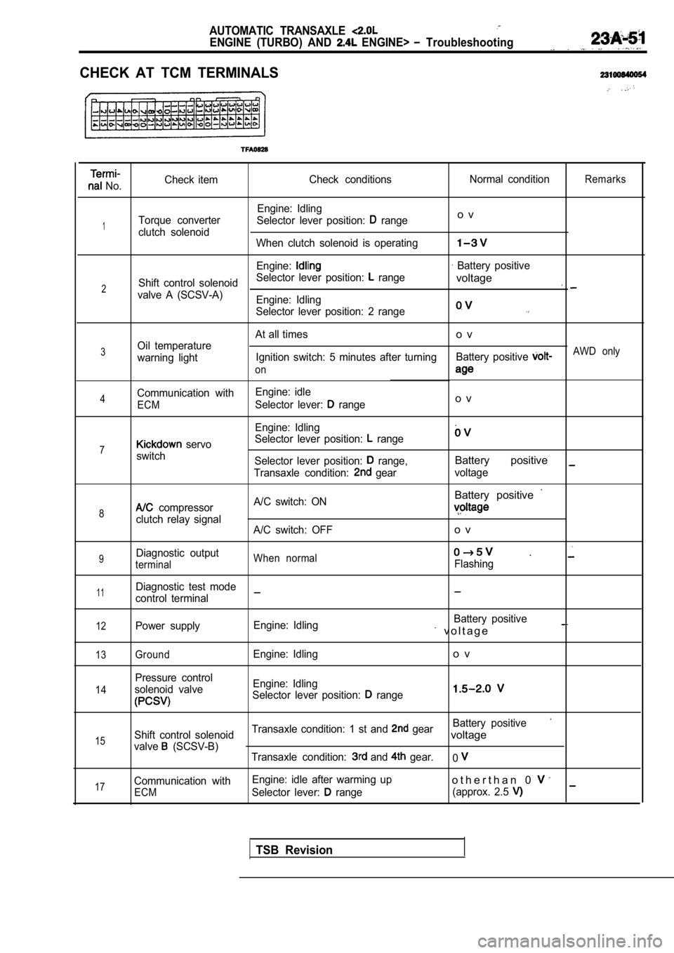
CHECK AT TCM TERMINALS
No.Check item
Check conditions Normal conditionRemarks
Engine: Idling
Torque converter Selector lever position:
rangeo v
1clutch solenoid
When clutch solenoid is operating
Engine: Battery positive
Shift control solenoid Selector lever position:
range
2voltage
valve A (SCSV-A)
Engine: Idling
Selector lever position: 2 range
At all timeso v
3Oil temperature
warning light Ignition switch: 5 minutes after turning
Battery positive AWD only
on
Communication with Engine: idle4Selector lever: rangeo vECM
Engine: Idling
Selector lever position:
range7 servo
switch Selector lever position:
range,Battery positive
Transaxle condition: gearvoltage
Battery positive
8 compressor A/C switch: ON
clutch relay signal
A/C switch: OFFo v
9Diagnostic outputWhen normal .
terminalFlashing
11Diagnostic test mode
control terminal
12Power supply Engine: Idling Battery positive v o l t a g e
13
14
15
17
GroundEngine: Idlingo v
Pressure control
solenoid valve Engine: Idling
Selector lever position:
range
Battery positive
Shift control solenoid Transaxle condition: 1 st and gearvoltage
valve (SCSV-B)
Transaxle condition: and gear.0
Communication with Engine: idle after warming upo t h e r t h a n 0
ECMSelector lever: range
(approx. 2.5
TSB Revision
Page 1060 of 2103

AUTOMATIC TRANSAXLE
ENGINE (TURBO) AND ENGINE> Troubleshooting
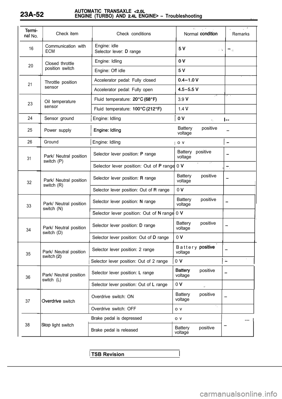
No.Check item
Check conditionsNormalRemarks
16Communication withEngine: idle
ECMSelector lever: range
20Closed throttle
position switch Engine: Idling
Engine: Off idle
21
23
24
25
26
31
32
33
34
35
36
37
38
Throttle position
sensor Accelerator pedal: Fully closed
Accelerator pedal: Fully open
Oil temperature
sensor Fluid temperature:
Fluid temperature:
3.9
1.4
Sensor ground Engine: IdlingI--
Power supplyBattery positive
voltage
Ground Engine: IdlingIo v
Park/ Neutral position
Selector lever position: rangeBattery positive
switch (P) voltage
Selector lever position: Out of range 0
Park/ Neutral position
Selector lever position: rangeBattery positive
switch (R) voltage
Selector lever position: Out of
range0
Park/ Neutral position Selector lever position: rangeBattery positive
switch (N) voltageSelector lever position: Out of range 0
Park/ Neutral position
Selector lever position: rangeBattery positive
switch (D) voltage
Selector lever position: Out of
range0
Park/ Neutral position Selector lever position: 2 rangeB a t t e r y
switchvoltage
Selector lever position: Out of 2 range 0
Park/ Neutral position
Selector lever position: range positive
switch (L)voltage
Selector lever position: Out of
range0
switch Overdrive switch: ON
Overdrive switch: OFF
Battery positive
voltage
o v
Brake pedal is depressedo v--- I
light switch Brake pedal is releasedBattery positive voltage
TSB Revision
Page 1066 of 2103
AUTOMATIC: TRANSAXLE
ENGINE AND On-vehicle Service
switch
Name
Data link connector
servo switch
OD-OFF switch
Oil temperature sensor
Oil temperature sensor
Park/neutral position switch
Revision
I
Page 1070 of 2103

AUTOMATIC TRANSAXLE
ENGINE (TURBO) AND ENGINE> On-vehicle Service
Revision
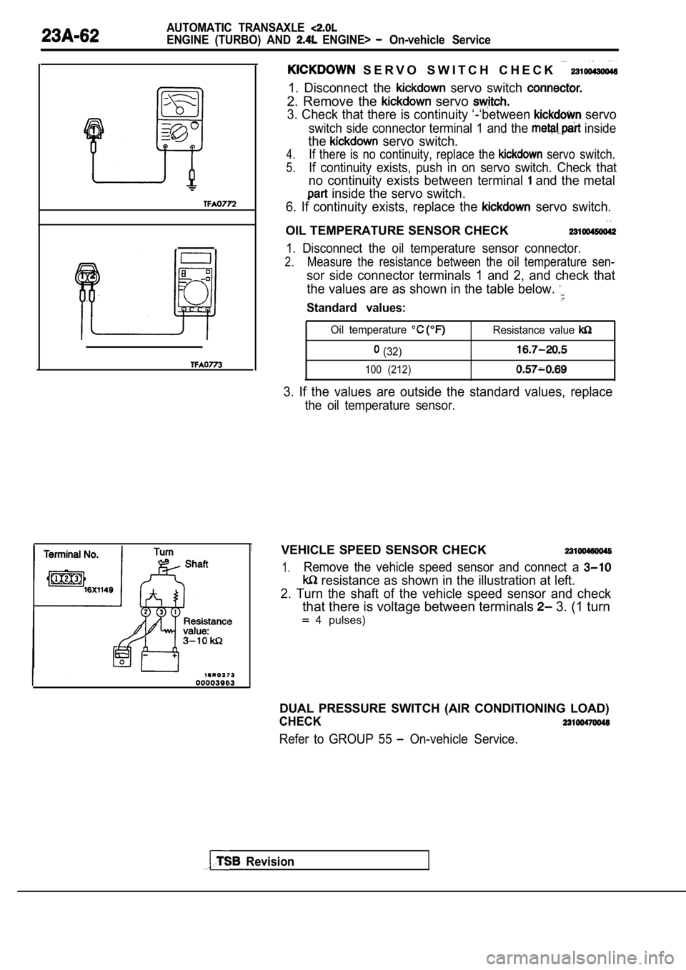
S E R V O S W I T C H C H E C K
1. Disconnect the servo switch
2. Remove the servo
3. Check that there is continuity ‘-‘between servo
switch side connector terminal 1 and the inside
the servo switch.
4.If there is no continuity, replace the servo switch.
5.If continuity exists, push in on servo switch. Check that
no continuity exists between terminal and the metal
inside the servo switch.
6. If continuity exists, replace the
servo switch.
OIL TEMPERATURE SENSOR CHECK
1. Disconnect the oil temperature sensor connector.
2.Measure the resistance between the oil temperature sen-
sor side connector terminals 1 and 2, and check that
the values are as shown in the table below.
Standard values:
Oil temperature Resistance value
(32)
100 (212)
3. If the values are outside the standard values, r eplace
the oil temperature sensor.
VEHICLE SPEED SENSOR CHECK
1.Remove the vehicle speed sensor and connect a
resistance as shown in the illustration at left.
2. Turn the shaft of the vehicle speed sensor and c heck
that there is voltage between terminals 3. (1 turn
4 pulses)
DUAL PRESSURE SWITCH (AIR CONDITIONING LOAD)
CHECK
Refer to GROUP 55 On-vehicle Service.
Page 1095 of 2103
AUTOMATIC TRANSAXLE
ENGINE (TURBO) AND ENGINE> On-vehicle Service
23100170047
1. Drain out the automatic transmission fluid.
2. Remove the oil pan.
3. Remove the oil filter.
4. Remove the oil temperature sensor.
5.Press the solenoid valve harness grommet and connec tor
into the transaxle case.
6.Press the catches of the solenoid valve harness grommets
and pass the connector through the case hole.
7.Remove the valve body assembly. The manual
come out, so be careful not to drop it.
valve can
Page 1098 of 2103

AUTOMATIC TRANSAXLE
ENGINE (TURBO) AND ENGINE> On-vehicle
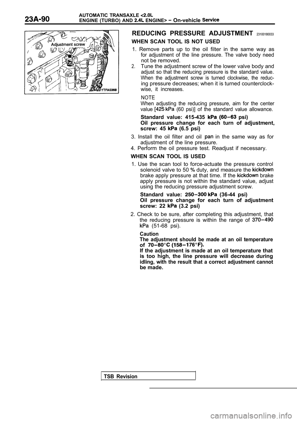
REDUCING PRESSURE ADJUSTMENT 23100180033
WHEN SCAN TOOL IS NOT USED 1. Remove parts up to the oil filter in the same wa y as
for adjustment of the line pressure. The valve body need
not be removed.
2.Tune the adjustment screw of the lower valve body a nd
adjust so that the reducing pressure is the standard value.
When the adjustment screw is turned clockwise, the reduc-
ing pressure decreases; when it is turned counterclock-
wise, it increases.
NOTE
When adjusting the reducing pressure, aim for the c enter
value
(60 psi)] of the standard value allowance.
Standard value: 415-435 psi)
Oil pressure change for each turn of adjustment,
screw: 45
(6.5 psi)
3. Install the oil filter and oil
in the same way as for
adjustment of the line pressure.
4. Perform the oil pressure test. Readjust if neces sary.
WHEN SCAN TOOL IS USED 1. Use the scan tool to force-actuate the pressure control
solenoid valve to 50
duty, and measure the
brake apply pressure at that time. If the brake
apply pressure is not within the standard value, ad just
using the reducing pressure adjustment screw.
Standard value:
(36-44 psi)
Oil pressure change for each turn of adjustment
screw: 22
(3.2 psi)
2. Check to be sure, after completing this adjustme nt, that
the reducing pressure is within the range of
(51-68 psi).
Caution
The adjustment should be made at an oil temperature
of
If the adjustment is made at an oil temperature tha t
is too high, the line pressure will decrease during
idling, with the result that a correct adjustment c annot
be made.
TSB Revision