Page 692 of 2103
14-2ENGINE COOLING General Information
GENERAL INFORMATION , ,
The cooling system is designed to keep every partthat the heat absorbed by the coolant may be of the engine at appropriate temperature in diated into the air.
er condition the engine may be operated.
The cooling of the water-cooled, pressureThe water pump is of the centrifugal type and is
driven by the
the
forced circulation type in which the water pump crankshaft. .
pressurizes coolant and circulates it throughout th e
engine: If the coolant temperature exceeds the
scribed temperature, the thermostat opens to circu-
late the coolant through the radiator as well so
and is cooled the
CONSTRUCTION DIAGRAM
Engine (Non-turbo)>
Radiator
Radi
.
oil cooler hose and pipe
Engine (Turbo)>
Radiator fan assembly
(Air cooled) oil cooler hose and pipetank
TSB Revision
Page 693 of 2103
G e n e r a l
ENGINE COOLING
Engine>
Radiator fan assemblyReserve tank
(Airoilcooler
cooled) oil cooler hose and pipe
SERVICE SPECIFICATIONS
ItemsStandard valueLimit
ThermostatValve opening temperature of Engine (Non-turbo)90.5 (195) thermostat Engine (Turbo) and Engine 82 (180)
Full-opening temperature of Engine (Non-turbo)
102 (216)
thermostat
Engine (Turbo) and Engine95 (203),
Radiator cap valve opening pressure (psi) Engine (Non-turbo)9 4 - 1 2 2 ( 1 4 - 1 8 )
Engine (Turbo) and Engine
LUBRICANT
ItemQuantity
Engine coolant HIGH QUALITY ETHYLENE GLYCOL ANTIFREE ZE COOLANT7.0 (7.4)
SEALANT
ItemSpecified sealant,
Thermostat case Engine (Turbo) and Engine>
Mitsubishi Genuine Parts No. or equivalent:
TSB Revision
Page 694 of 2103

E N G I N E C O O L I N G
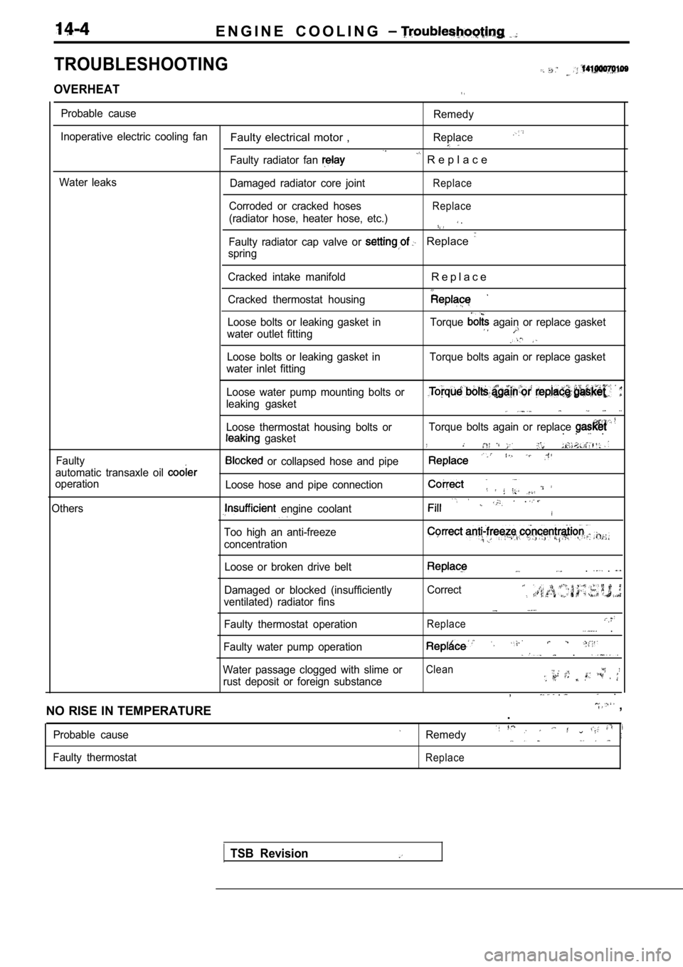
TROUBLESHOOTING
OVERHEAT
Probable cause
Inoperative electric cooling fan
Water leaks
Faulty electrical motor ,
Faulty radiator fan
Damaged radiator core joint
Corroded or cracked hoses
(radiator hose, heater hose, etc.)
Remedy
Replace
R e p l a c e
Replace
Replace
.
Faulty radiator cap valve or Replace
spring
Cracked intake manifold
Cracked thermostat housing
R e p l a c e
Loose bolts or leaking gasket in
water outlet fitting Torque again or replace gasket
Loose bolts or leaking gasket in
water inlet fitting Torque bolts again or replace gasket
Faulty Loose water pump mounting bolts or
leaking gasket
Loose thermostat housing bolts or
gasket
automatic transaxle oil
operation
Others
or collapsed hose and pipe
Loose hose and pipe connection
engine coolant
Too high an anti-freeze
concentration
Torque bolts again or replace . . .
.
Loose or broken drive belt
Damaged or blocked (insufficiently
ventilated) radiator fins
Faulty thermostat operation. .
Correct
Replace .
Faulty water pump operation .
Water passage clogged with slime orClean
rust deposit or foreign substance, . .
NO RISE IN TEMPERATURE
,
.
Probable cause
Faulty thermostatRemedy
Replace
TSB Revision
Page 721 of 2103
INTAKE AND EXHAUST Intake Manifold Engine
REMOVAL AND INSTALLATION
Operationl Residual Fuel Pressure Releasing(Refer to GROUP Service.)l Engine Coolant Draining(Refer to GROUP Service.)l Reservoir Assembly Removal with Auto-Cruise
2.9
Post-installation Operationl Reservoir Assembly Installation
l Engine Coolant Supplying (Refer to GROUP Service.)l Accelerator Cable Adjustment (Refer to GROUP 17 On-vehicle Service.)
3.92 . 9
O-ring
Engineoil
Removalsteps
1. Air intake hose2.Breather hose
3. Accelerator cable connection
4. Clip5. MAP sensor connector
6. Charge temperature sensor connector
7. Vacuum hose connection
8.TPS connector9. motor connector 10.
wiring harness11. connection
12. PCV hose assembly 13. Vacuum hose connection14. Brake booster hose
connection
15. pipe connection
16. fuel hose connection
TSB Revision
Page 725 of 2103

INTAKE AND EXHAUST Intake Manifold Engine
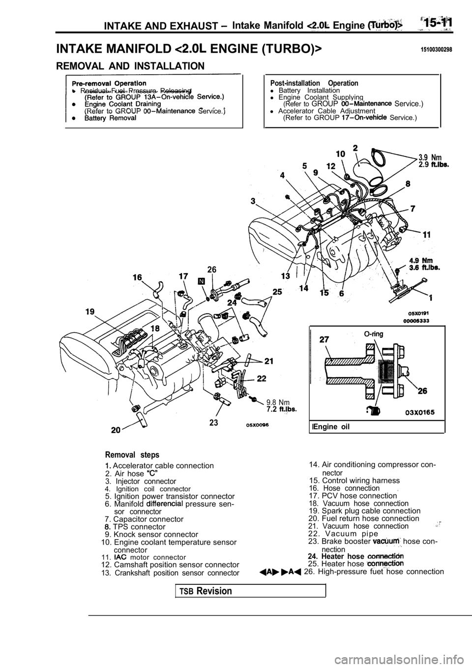
INTAKE MANIFOLD ENGINE (TURBO)>15100300298
REMOVAL AND INSTALLATION
l Residual Fuel Pressure Releasing
(Refer to GROUP
Service.)
26
Post-installation Operationl Battery Installation
l Engine Coolant Supplying
(Refer to GROUP Service.)l Accelerator Cable Adjustment
(Refer to GROUP Service.)
3.9 Nm2.9
9.8 Nm7.2
23
Removal steps
Accelerator cable connection
2. Air hose
3. Injector connector4. Ignition coil connector 5. Ignition power transistor connector
6. Manifold
pressure sen-sor connector
14. Air conditioning compressor con-
7. Capacitor connector
TPS connector
9. Knock sensor connector
10. Engine coolant temperature sensor
connector11. motor connector
12. Camshaft position sensor connector
13. Crankshaft position sensor connector nector
15. Control wiring harness16. Hose connection.17. PCV hose connection18. Vacuum hose connection19. Spark plug cable connection
20. Fuel return hose connection
21. Vacuum hose connection2 2 . V a c u u m p i p e
23. Brake booster hose con-
nection24. Heater hose 25. Heater hose 26. High-pressure fuet hose connection
IEngine oil
TSBRevision
Page 1009 of 2103

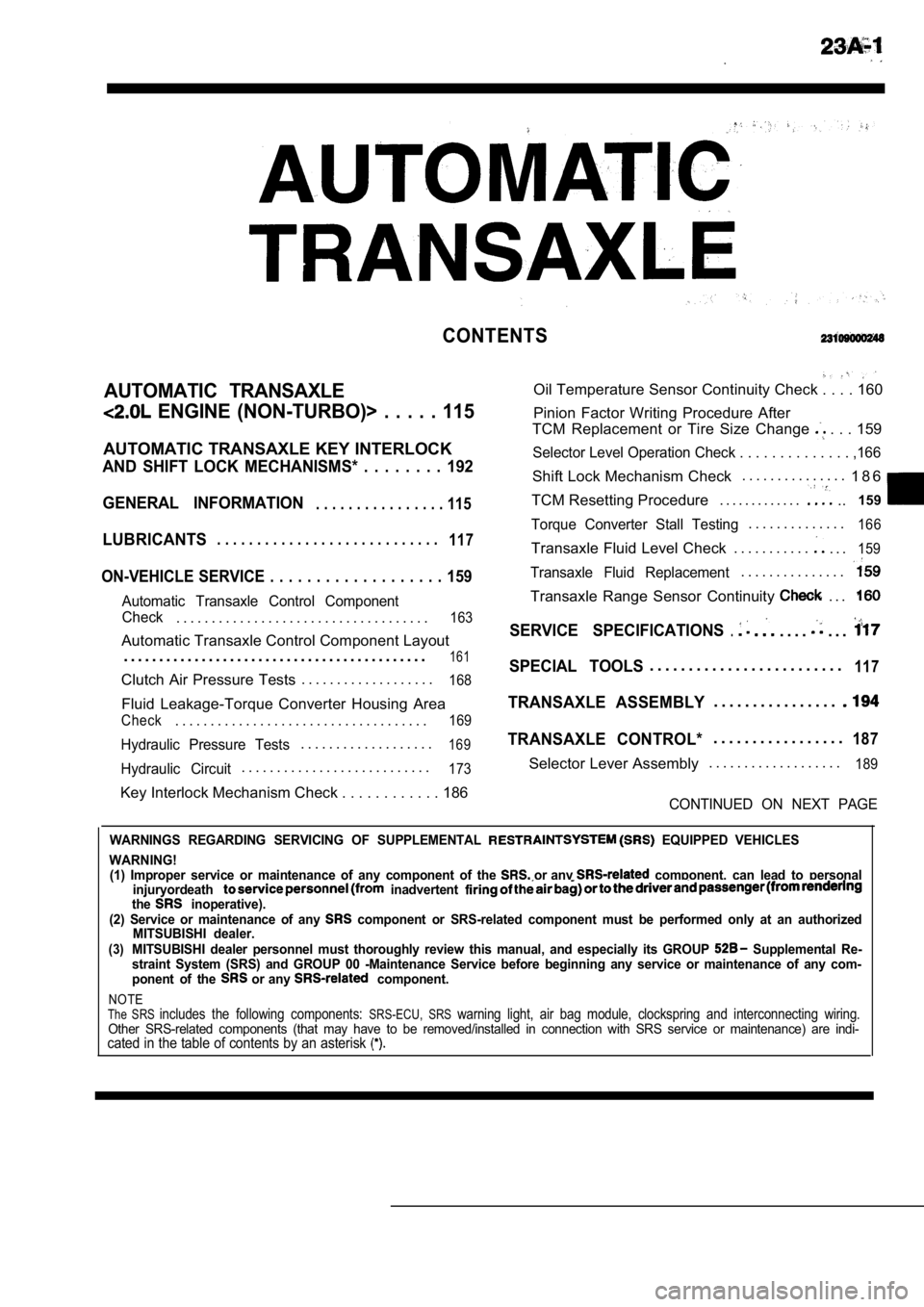
CONTENTS
AUTOMATIC TRANSAXLE
ENGINE (NON-TURBO)> . . . . . 115
AUTOMATIC TRANSAXLE KEY INTERLOCK
AND SHIFT LOCK MECHANISMS* . . . . . . . . 192
GENERAL INFORMATION
. . . . . . . . . . . . . . . . 115
LUBRICANTS. . . . . . . . . . . . . . . . . . . . . . . . . . . .117
ON-VEHICLE SERVICE . . . . . . . . . . . . . . . . . . . 159
Automatic Transaxle Control Component
Oil Temperature Sensor Continuity Check . . . . 160
Pinion Factor Writing Procedure After
TCM Replacement or Tire Size Change
. . . 159
Selector Level Operation Check . . . . . . . . . . . . . . ,166
Shift Lock Mechanism Check. . . . . . . . . . . . . . .
1 8 6
TCM Resetting Procedure . . . . . . . . . . . . .
..159
Torque Converter Stall Testing. . . . . . . . . . . . . .166
Transaxle Fluid Level Check . . . . . . . . . . .. . .159
Transaxle Fluid Replacement. . . . . . . . . . . . . . .
Transaxle Range Sensor Continuity . . .
Check. . . . . . . . . . . . . . . . . . . . . . . . . . . . . . . . . . . .163SERVICE SPECIFICATIONS.. . . .. . .Automatic Transaxle Control Component Layout
. . . . . . . . . . . . . . . . . . . . . . . . . . . . . . . . . . . . . . . . . . .
161SPECIAL TOOLS. . . . . . . . . . . . . . . . . . . . . . . . .117Clutch Air Pressure Tests . . . . . . . . . . . . . . . . . . .168
Fluid Leakage-Torque Converter Housing Area
Check. . . . . . . . . . . . . . . . . . . . . . . . . . . . . . . . . . . .169
Hydraulic Pressure Tests. . . . . . . . . . . . . . . . . . .169
Hydraulic Circuit. . . . . . . . . . . . . . . . . . . . . . . . . . .173
TRANSAXLE ASSEMBLY. . . . . . . . . . . . . . . .
TRANSAXLE CONTROL*. . . . . . . . . . . . . . . . .187
Selector Lever Assembly. . . . . . . . . . . . . . . . . . .189
Key Interlock Mechanism Check . . . . . . . . . . .
. 186CONTINUED ON NEXT PAGE
WARNINGS REGARDING SERVICING OF SUPPLEMENTAL EQUIPPED VEHICLES
WARNING! (1) Improper service or maintenance of any componen t of the
or any component, can lead to personal
injuryordeath inadvertent the inoperative).
(2) Service or maintenance of any component or SRS-related component must be perform ed only at an authorized
MITSUBISHI dealer.
(3)MITSUBISHI dealer personnel must thoroughly review this manual, and especially its GROUP Supplemental Re-
straint System (SRS) and GROUP 00 -Maintenance Serv ice before beginning any service or maintenance of any com-
ponent of the
or any component.
NOTEThe SRS includes the following components: SRS-ECU, SRS warning light, air bag module, clockspring and inte rconnecting wiring.Other SRS-related components (that may have to be removed/installed in connection with SRS service or maintenance) are indi-cated in the table of contents by an asterisk
Page 1016 of 2103

AUTOMATIC TRANSAXLE ENGINEService
( T U R B O ) A N D E N G I N E > - . .
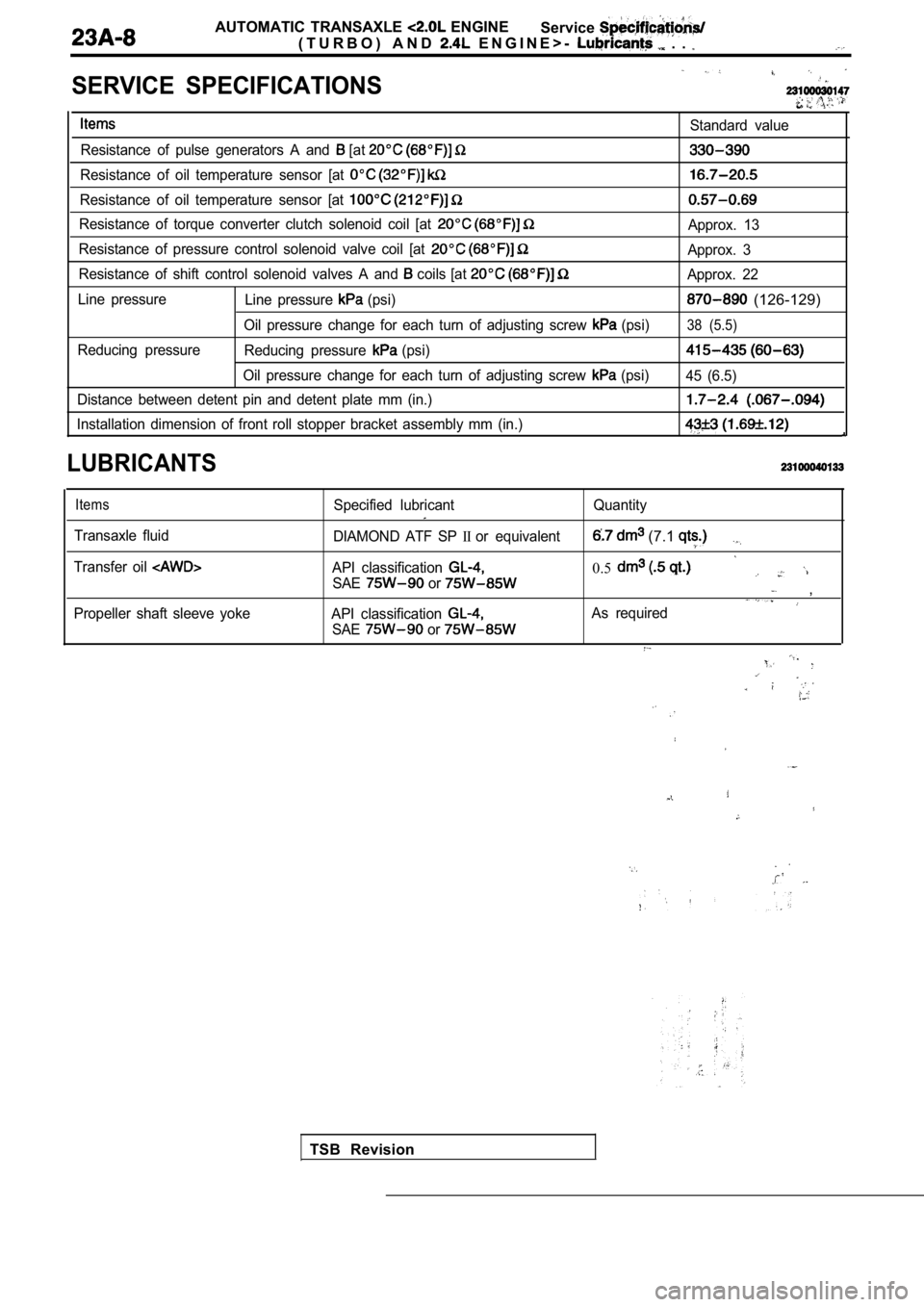
SERVICE SPECIFICATIONS
Standard value
Resistance of pulse generators A and
[at
Resistance of oil temperature sensor [at
Resistance of oil temperature sensor [at
Resistance of torque converter clutch solenoid coil [at Approx. 13
Resistance of pressure control solenoid valve coil [at
Approx. 3
Resistance of shift control solenoid valves A and
coils [at Approx. 22
Line pressure Line pressure
(psi) (126-129)
Oil pressure change for each turn of adjusting scre w (psi)38 (5.5)
Reducing pressure
Reducing pressure (psi)
Oil pressure change for each turn of adjusting scre w (psi)
45 (6.5)
Distance between detent pin and detent plate mm (in .)
Installation dimension of front roll stopper bracket assembly mm (in.)
LUBRICANTS
Items
Transaxle fluid
Transfer oil
Propeller shaft sleeve yoke Specified lubricant
Quantity
DIAMOND ATF SP
IIor equivalent (7.1
API classification 0.5SAE or ,
API classification As required
SAE
or
TSB Revision
Page 1027 of 2103

AUTOMATIC TRANSAXLE ENGINE
(TURBO) AND
ENGINE> Troubleshooting
INSPECTION CHART FOR DIAGNOSTIC TROUBLE CODES
CodeDiagnostic item Reference page
11Throttle position sensor system Excessive
output
12Throttle position sensor systemoutput
13Throttle position sensor system Defective
sensor
14Throttle position sensor system Defective
sensor
adjustment
15
16
21
22
23
Oil temperature sensor system
Oil temperature sensor system
servo switch system
servo switch system
Ignition signal system Open circuit
Short circuit
Open circuit
Short circuit
Open circuit
22
22
22
28
31
32
36
Stop light switch system
Pulse generator A (PG-A) system
Pulse generator
(PG-B) system
Park/Neutral position switch svstem Short circuit
Open circuit
Open circuit Short circuit
23
24
25
26
Torque
converter
37
41
42
43
Park/Neutral position switch system
Shift control solenoid valve A (SCSV-A) system
Shift control solenoid valve A (SCSV-A) system
Shift control solenoid valve
(SCSV-B) system Open circuit
Open circuit
Short circuit
Open circuit
26
27
27
27
Revision