Page 578 of 1273
14-26COOLING - Water Hose and Water Pipe
WATER HOSE AND WATER PIPE
REMOVAL AND INSTALLATION
MlUA-B
IF‘re-removal and Post-installationOperation eDraIning
and Supplying of the En- glne
Coolant
(Refer to GROUP
00-Maintenance Service.)
12-15 Nm
9-11 ftlbs.
12-15 ‘Nm9-11 ft.lbs.
25-30 Nm’ 7
18-22
ft.lbs.68
A
40 50 Nm’&\29136 ft.lbs.4Ib.
q 2,h
40-50 Nm
9-11 ft.lbs.
30-40 Nm22 - 29 ft.lbs.
30-40 Nm\22-29 ft.lbs. \ OSAOOSS
Removal steps
1. Condenser fan motor assembly(FWD,
AWD-M/T)
2 Self-locking nut
3. Gasket4. Connection for oxygen sensor
5. Exhaust manifold cover (A)
6. Self-locking nut
7. Engine hanger
8. Exhaust manifold
9. Exhaust manifold gasket
10. Exhaust manifold cover (B)
1 TSB Revision
Page 579 of 1273
COOLING - Water Hose and Water PiDe 14-27
-55 Nm
Removal steps
11. Connection for oxygen sensor andcontrol harness
12. Water hose
13. Water by-pass hose
14. Connection for heater hose
15. Connection for radiator lower hose (Referto P.14-10.)
16. Water inlet pipe (Refer to P.14-18.)17. O-ring (Refer toP.14-18.)
04A0050
TSB Revision
Page 580 of 1273
14-28COOLING - Water Hose and Water Pipe
WATER HOSE AND WATER PIPE
Pre-removal and Post-installation Operation 1eDraining and Filling of the Engine Coolant
(Refer to GROUP 00-Maintenance Service.)
*Draining and Filling of the Engine Oil
(Refer to GROUP 11 -Service Adjustment Pro-
cedures.)
REMOVAL AND INSTALLATION
12-15 Nm
9-l 1 ft.lbs.25-30 Nm18-24 ft.lbs.
M141A-C
‘1
Flare nut 55-65
N
m
/-A 40-47 ft.lbs.
12-15 Nk9-11
ftlbs.
30-40 Nm
22-29 ft.lbs:
,“k.
Removal steps
I. Radiator (Refer to P.14-9.)2. Connection for air intake hose
3. Connection for vacuum hose
4. Connection for air hose A
5. Air outlet fitting6. Gasket
7. Heat protector A
8. Heat protector
B9. Self-locking nut10. Engine hanger
\40-50 Nm
29-36 ftlbs.
05Aoo54\40-60 Nm
29-43 ft.lbs.
II. Eye bolt12. Gasket
13. Connection for water hose
I 4. Connection for water pipe B15. Self-locking nut16. Gasket -17. Exhaust manifold
18. Exhaust manifold gasket
19. Ring
20. Gasket
i TSB Revision
Page 582 of 1273
14-30COOLING - Water Hose and Water Pipe
05AOO26
SERVICE POINTS OF REMOVALMWBAG
24. REMOVAL OF TURBOCHARGER ASSEMBLYRemove the turbocharger assembly with the exhaust
fitting, water pipe A, water pipe
B and the oil pipe attached
to it.
INSPECTION
WATER PIPE AND HOSE INSPECTION
Refer to
P.14-23.
Ml4lcAE
SERVICE POINTS OF INSTALLATIONMWDAR
24. INSTALLATION OF TURBOCHARGER ASSEMBLY Clean the alignment surfaces shown in the illustration.
Caution
When cleaning, care must be taken so that a piece of
the gasket does not enter the oil passage hole.
TSB Revision
Page 583 of 1273
COOLING -Engine Coolant Temperature Gauge Unit, Engine CoolantTemoerature Sensor and Engine Coolant Temperature Switch14-31
ENGINE COOLANT TEMPERATURE GAUGE UNIT, ENGINE COOLANT
TEMPERATURE SENSOR AND ENGINE COOLANT TEMPERATURE
SWITCHM14oE-
REMOVAL AND INSTALLATION
30-40
Nm/
gine Coolantlo-14 Nm(Refer to GROUP 00-Maintenance8-10 ft.lbs.Service.)
/ I r lcoolo
Sealant: 3M ATD Part No.8660or equivalent04A0118
< 1993 models>
10 12 Nrny~~~~~7-9 ft.lbs. 2
1. Engine coolant temperature gauge unit
2. Engine coolant temperature sensor
(Engine control)3. Air conditioning engine coolanttemperature switch
type>4. Engine coolant temperature switch, . (Air condltloning
or A/T control)
Sealant: 3M Nut locking PartNo.4171 or equivalent
TSB Revision
Page 584 of 1273

14-32COOLING -Engine Coolant Temperature Gauge Unit, Engine Coolant
Temperature Sensor and Engine Coolant Temperature Switch
/
Sensor
J
046003
3
04GOO32
9FUO156
---
--I ‘Oi
l
QQQQQQ2cmn99
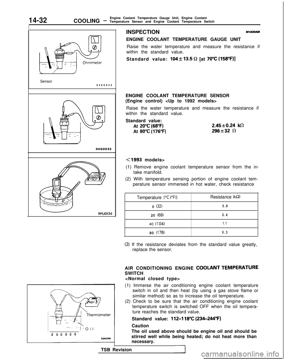
INSPECTIONM14OOAM
ENGINE COOLANT TEMPERATURE GAUGE UNIT
Raise the water temperature and measure the resistance if
within the standard value.
Standard value:
104k13.5 Q [at 70°C (158”F)]
ENGINE COOLANT TEMPERATURE SENSOR
(Engine control)
Raise the water temperature and measure the resistance if
within the standard value.
Standard value:
At
20°C (68°F)
At 80°C (176°F) 2.4520.24
klR
296232 R
<1993 models>
(1) Remove engine coolant temperature sensor from the in- take manifold.
(2) With temperature sensing portion of engine coolant tem- perature sensor immersed in hot water, check resistance
Temperature 1°C (OF)1Resistance (kR)
0 (32)5.8
20 (68)2.4
40
(I
04)1.1
80 (176)0.3
(3) If the resistance deviates from the standard value greatly,
replace the sensor.
AIR CONDITIONING ENGINE
COOLANT TEMPERATURE
SWITCH
(1) Immerse the air conditioning engine coolant temperature switch in oil and then heat (by using a gas stove flame or
similar method) so as to increase the oil temperature.
(2) Check to be sure that the air conditioning engine coolant temperature switch is switched OFF when the oil tempera-ture reaches the standard value.
Standard value:
112-l 18°C (234-244°F)
Caution
The oil used above should be engine oil and should be
stirred well while being heated; do not heat more than
necessary.
TSB Revision
Page 585 of 1273
COOLING -Engine Coolant Temperature Gauge Unit, Engine Coolant
Temperature Sensor and Engine Coolant Temperature Switch14-33
20R0586
ENGINE COOLANT TEMPERATURE SWITCH
(Air conditioning or A/T control)
(1) Remove the engine coolant temperature switch from the
water outlet fitting.
(2) immerse the engine coolant temperature switch in oil and heat by a gas stove or similar method so as to increase the
oil temperature.
(3) Check to be sure that the engine coolant temperature switch is switched ON when the oil temperature reaches
the standard value.
Standard value:
lOO-104% (212-219°F)
CautionUse engine oil for this test; stir it well while heating,
and do not heat more than necessary.
TSB Revision
1
Page 602 of 1273

15-16INTAKE AND EXHAUST- Intake Manifold
05AOO89
I05A0081
(
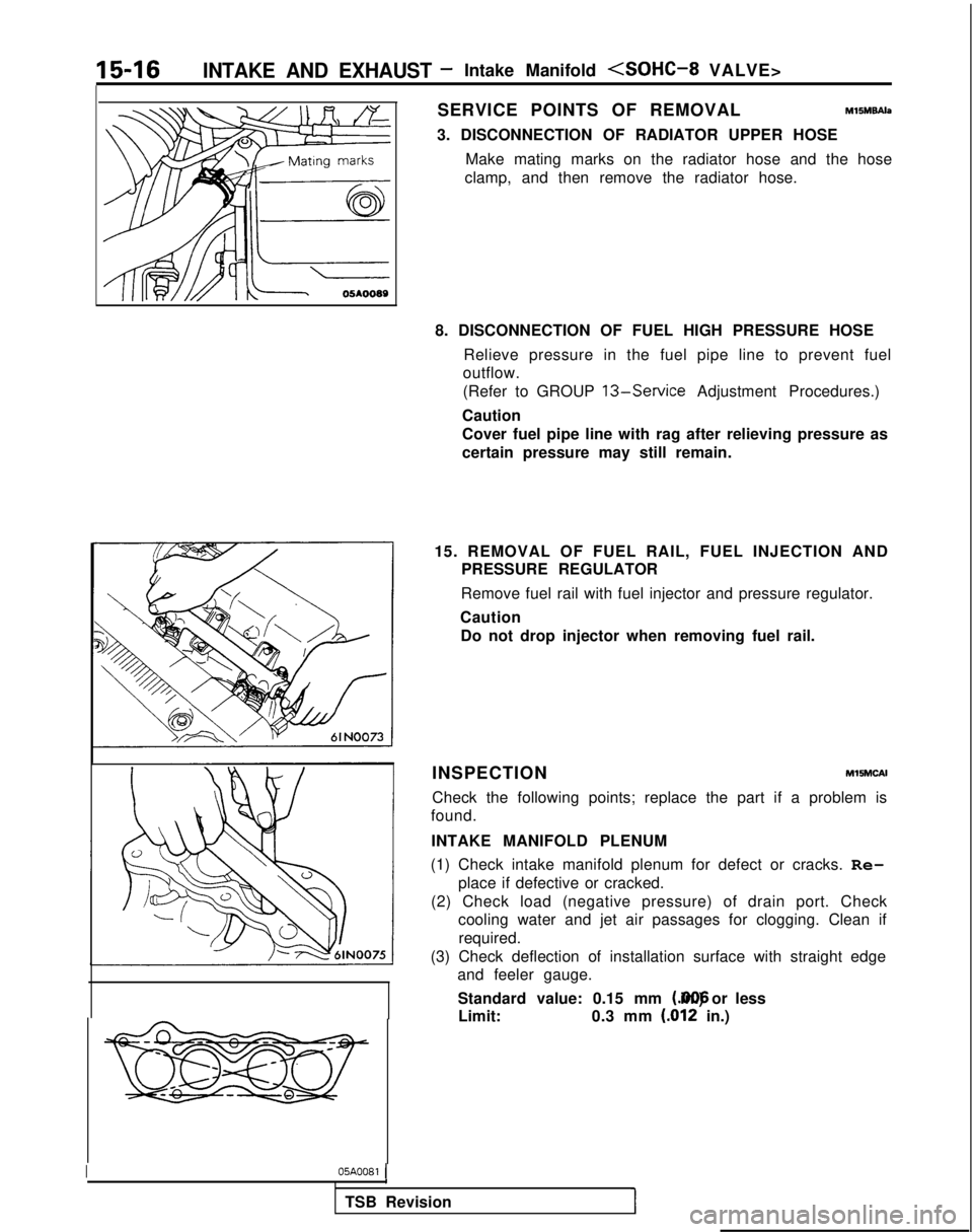
SERVICE POINTS OF REMOVALM15M9Ah
3. DISCONNECTION OF RADIATOR UPPER HOSE
Make mating marks on the radiator hose and the hose
clamp, and then remove the radiator hose.
8. DISCONNECTION OF FUEL HIGH PRESSURE HOSE Relieve pressure in the fuel pipe line to prevent fuel
outflow.
(Refer to GROUP
13-Service Adjustment Procedures.)
Caution
Cover fuel pipe line with rag after relieving pressure as
certain pressure may still remain.
15. REMOVAL OF FUEL RAIL, FUEL INJECTION AND PRESSURE REGULATOR
Remove fuel rail with fuel injector and pressure regulator.
Caution Do not drop injector when removing fuel rail.
INSPECTION
MlSMCAI
Check the following points; replace the part if a problem is
found.
INTAKE MANIFOLD PLENUM
(1) Check intake manifold plenum for defect or cracks. Re- place if defective or cracked.
(2) Check load (negative pressure) of drain port. Check cooling water and jet air passages for clogging. Clean if
required.
(3) Check deflection of installation surface with straight edge and feeler gauge.
Standard value: 0.15 mm (.006 in.) or less
Limit: 0.3 mm
(.012 in.)
1
TSB Revision