1989 MITSUBISHI GALANT cooling
[x] Cancel search: coolingPage 1 of 1273
BACKUP
Service Manual
GRLRNT
1989-1990-1991-1992-1993
Volume 1
Chassis & Mechanical
FOREWORD
This Service Manual has been prepared with thelatest service information available at the time of
publication. It is subdivided into various group cate-
gories and each section contains diagnostic, dis-
assembly, repair, and installation procedures along
with complete specifications and tightening ref-
erences. Use of this manual will aid in properly per-
forming any servicing necessary to maintain or res-
tore the high levels of performance and reliability
designed into these outstanding vehicles.
This BACKUP DSM manual is to be used DNLY as
a SACKUP. please DIJ NOT REDISTRIBUTEWHOLE SECTIONS. This BACKUP was sold to you under the fact that you do indeed
DWNa GENUINE DSM MANUAL. It CANNOT BE considered a REPLACEMENT (Unless your
original
manual was lost or
destroyed.) Please
See
README.TXT
or
README.HTML
for additional
information.
1kyou.
- Gjmpiemym_ay&?h
@
A
.
.”
WE SUPPORT
VOLUNTARY TECHNICIAN
CERTIFICATION THROUGH
Nallonal lnsrltule forAU~~~v3~;VPCT:VE
EXCELLENCE naiLcorn
MITSUBISHIMOTOR SALES OF AMERICA. Inc.
Mltsublshl Motors Corporat!on reserves the right to make changes indesign or to make additions to or Improvements In Its products
wlthout~mposng any obllgatlons upon Itself to install them on its productspreviously manufactured
0 1992 Mitsubishi Motors CorporationRcprintedinUSA
GROUP INDEXMOOAA-
General.........................................................
Engine...........................................................
Fuel................................................................
Cooling.........................................................
Intake and Exhaust..............................
Emission Control....................................
Clutch............................................................
Manual Transaxle..................................
Automatic Transaxle............................
Propeller Shaft........................................
Front Axle..................................................
Rear Axle....................................................
Wheel and Tire.......................................
Power Plant Mount..............................
Front Suspension...................................
Active-Electronic
Control Suspension..............................m
A
Rear Suspension....................................&
Service Brakes.........................................
Parking Brakes........................................
Alphabetical Index.................................
NOTE: Electrical system Information is contained in
Volume 2 “Electrical” of this paired Service Manual.
For overhaul procedures of engines or transmissions,
refer to the separately issued Engine
Service Manual
or Manual/Automatic Transmission Service Manual.
Page 38 of 1273
00-36
GENERAL -Recommended Lubricants and Lubricant Capacities Table
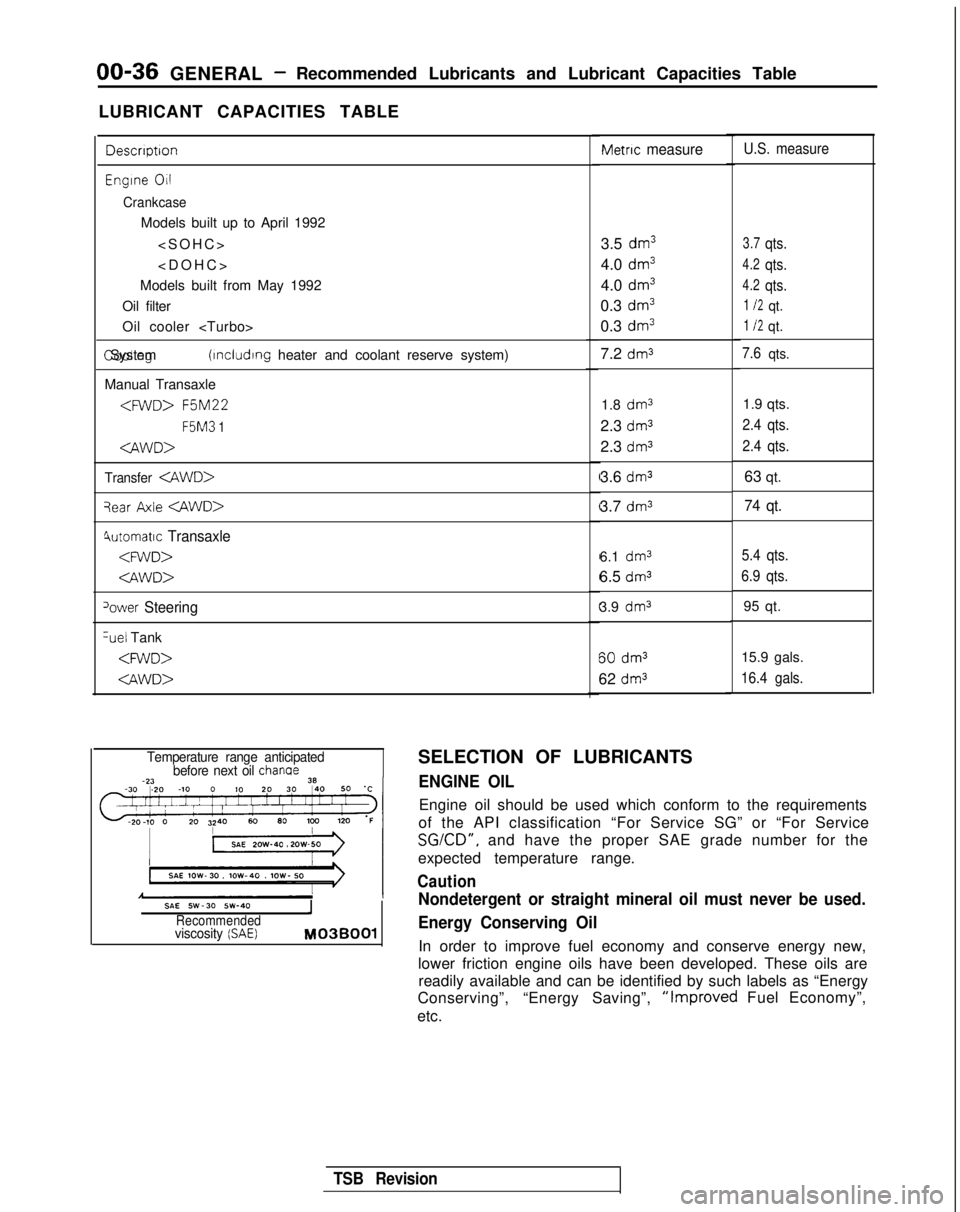
LUBRICANT CAPACITIES TABLE
Descrrptron
Engrne 011
Crankcase
Models built up to April 1992
Models built from May 1992
Oil filter
Oil cooler
(rncludrng heater and coolant reserve system)
Manual Transaxle
F5M3
1
Transfer
qear Axle
4utomatrc Transaxle
‘ower Steering %el
Tank
Metric measure
3.5 dm3
4.0 dm3
4.0 dm3
0.3 dm3
0.3 dm3
7.2 dm3
1.8 dm31.9 qts.
2.3
dm32.4 qts.
2.3 dm32.4 qts.
3.6 dm363 qt.
3.7
dm374 qt.
6.1 dm3
6.5 dms
3.9 dm3 60
dm3
62 dm3
U.S. measure
3.7qts.
4.2qts.
4.2qts.
1 I2qt.
1 I2qt.
7.6qts.
5.4 qts.
6.9 qts.
95 qt.
15.9 gals.
16.4 gals.
Temperature range anticipated before next oil chanae
SAE SW-30 SW-40IRecommendedviscosity (SAE) M03BOOl
SELECTION OF LUBRICANTS
ENGINE OIL
Engine oil should be used which conform to the requirements
of the API classification “For Service SG” or “For Service
SGKD”, and have the proper SAE grade number for the
expected temperature range.
Caution
Nondetergent or straight mineral oil must never be used.
Energy Conserving Oil
In order to improve fuel economy and conserve energy new,
lower friction engine oils have been developed. These oils are readily available and can be identified by such labels as “Energy
Conserving”, “Energy Saving”,
“Improved Fuel Economy”,
etc.
TSB Revision
Page 39 of 1273
GENERAL - Recommended LubricaMs and Lubricant Capacities Table 00-37
721004
4
Oil Identification Symbol
A standard
.symbol appears on the top of oil containers and has
three district areas for identifying various aspects of the oil.
The top
polqion will indicate the quality of the oil. The center
portion will show the SAE viscosity grade, such as SAE lOW-30.
“Energy Conserving” shown in the lower portion,
indicates that the oil has fuel-saving capabilities.
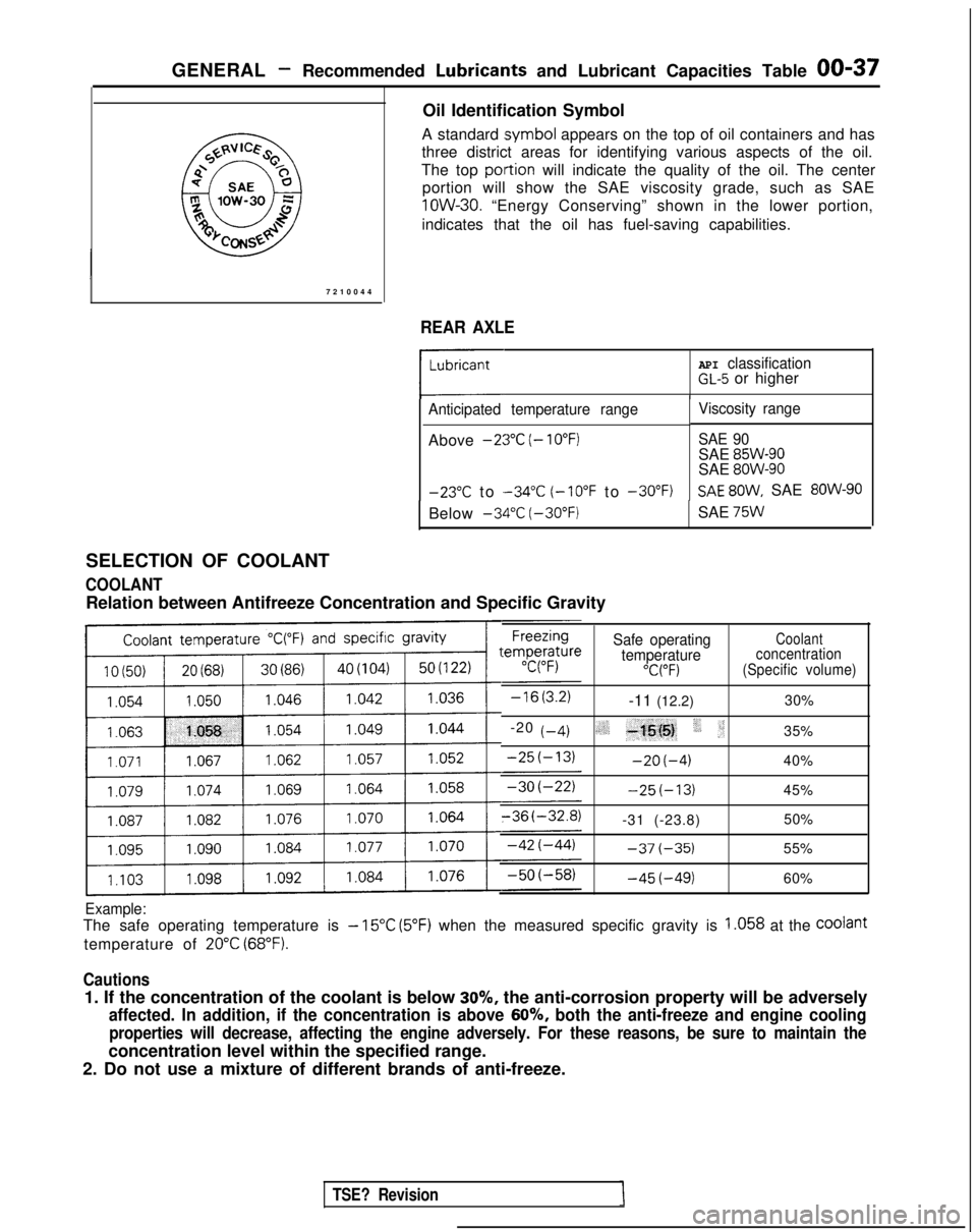
REAR AXLE
API classificationGL-5 or higher
Anticipated temperature range
Above -23°C
(- 10°F)
-23°C to --34°C (-10°F
to -30°F)
Viscosity range
SAE 90
SAE 85W-90SAE 8OW-90
SAE 8OW. SAE 8OW-90
Below
-34°C
(-30°F)SAE 75W
SELECTION OF COOLANT
COOLANT
Relation between Antifreeze Concentration and Specific Gravity
Safe operatingCoolant
temperatureconcentration
“C(“F)(Specific volume)
-11 (12.2) 30%
-20
t-4)(,.‘_ -+j{@, ‘, :;35%
-2O(-4)40%
-25(-13)45%
-31 (-23.8) 50%
-37(-35)55%
-45(-49)60%
Example:
The safe operating temperature is - 15°C (5°F) when the measured specific gravity is 1.058 at the Coolant
temperature of 20°C (68°F).
Cautions
1. If the concentration of the coolant is below 30%, the anti-corrosion property will be adversely
affected. In addition, if the concentration is above 60%, both the anti-freeze and engine cooling
properties will decrease, affecting the engine adversely. For these reas\
ons, be sure to maintain the
concentration level within the specified range.
2. Do not use a mixture of different brands of anti-freeze.
TSE? Revision
Page 46 of 1273
GENERAL -Maintenance Service
(1O)Star-t engine and allow to idle for at least two minutes.
Then, with parking brake on, move selector
fever
momentarily to each position, ending in “N” Neutral
position.
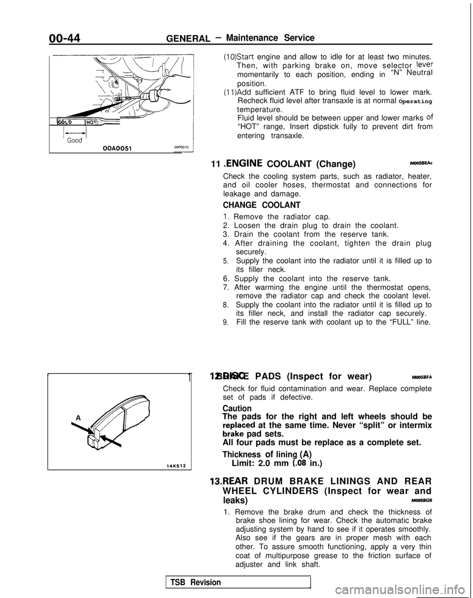
(11)Add sufficient ATF to bring fluid level to lower mark.
Recheck fluid level after transaxle is at normal Operating
temperature. Fluid level should be between upper and lower marks of
“HOT” range, Insert dipstick fully to prevent dirt from
entering transaxle.
OOA0051
11 .ENGINE
COOLANT (Change)MOOSEEAC
Check the cooling system parts, such as radiator, heater,
and oil cooler hoses, thermostat and connections for
leakage and damage.
CHANGE COOLANT
1. Remove the radiator cap.
2. Loosen the drain plug to drain the coolant.
3. Drain the coolant from the reserve tank.
4. After draining the coolant, tighten the drain plug securely.
5.Supply the coolant into the radiator until it is filled up to
its filler neck.
6. Supply the coolant into the reserve tank.
7. After warming the engine until the thermostat opens, remove the radiator cap and check the coolant level.
8.Supply the coolant into the radiator until it is filled up to
its filler neck, and install the radiator cap securely.
9.Fill the reserve tank with coolant up to the “FULL” line.
14K512
1 12.DISC BRAKE PADS (Inspect for wear) MWSBFA
Check for fluid contamination and wear. Replace complete
set of pads if defective.
Caution
The pads for the right and left wheels should be
reDlaced at the same time. Never “split” or intermix
brkke pad sets.
All four pads must be replace as a complete set.
Thickness of lining (A)
Limit: 2.0 mm (.08 in.)
13.REAR DRUM BRAKE LININGS AND REAR
WHEEL CYLINDERS (Inspect for wear and
leaks)MOOSBGB
1. Remove the brake drum and check the thickness of brake shoe lining for wear. Check the automatic brake
adjusting system by hand to see if it operates smoothly.
Also see if the gears are in proper mesh with each
other. To assure smooth functioning, apply a very thin
coat of multipurpose grease to the friction surface of
adjuster and link shaft.
TSB Revision1
Page 58 of 1273
II-8ENGINE
8 VALVE
W Tlmlng belt side
il6
16
727
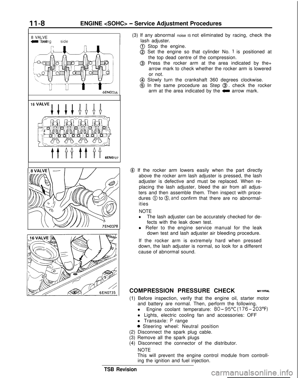
(3) If any abnormal noise IS not eliminated by racing, check the
lash adjuster.
@ Stop the engine.
@ Set the engine so that cylinder No. 1 is positioned at
the top dead centre of the compression.
@ Press the rocker arm at the area indicated by the+ arrow mark to check whether the rocker arm is lowered
or not.
@ Slowly turn the crankshaft 360 degrees clockwise.
@ In the same procedure as Step 0, check the rocker
arm at the area indicated by the
0 arrow mark.
@ If the rocker arm lowers easily when the part directly
above the rocker arm lash adjuster is pressed, the lash
adjuster is defective and must be replaced. When re-
placing the lash adjuster, bleed the air from all adjus-
ters and then assemble them. Then inspect with proce-
dures
@ to 0, and confirm that there are no abnormal-
ities
NOTE
lThe lash adjuster can be accurately checked for de-
fects with the leak down test.
l Refer to the engine service manual for the leak down test and lash adjuster air bleeding procedure.
If the rocker arm is extremely hard when pressed
down, the lash adjuster is normal, so look for a different
cause of abnormal sound.
COMPRESSION PRESSURE CHECK
MllFFAL
(1) Before inspection, verify that the engine oil, starter motor and battery are normal. Then, perform the following.
l Engine coolant temperature:
80- 95°C
(176- 203°F)
l Lights, electric cooling fan and accessories: OFF
l Transaxle:
P range
0 Steering wheel: Neutral position
(2) Disconnect the spark plug cable.
(3) Remove all the spark plugs
(4) Disconnect the connector of the distributor.
NOTE
This will prevent the engine control module from controll- ing the ignition and fuel injection.
TSB Revision
Page 59 of 1273

ENGINE
(5) Cover the spark plug holes with a cloth, etc., and crank the engine. Then verify that no foreign material sticks to the
cloth, etc.
Caution
1. During cranking, be especially careful of the spark plug
installing hole.
2.Very hot water, oil, fuel, etc., which may have entered
the cylinder somehow, will violently spout through the spark plug hole if the compression is measured in the
entrapped state. This is very dangerous.
MANIFOILD VACUUM INSPECTIONMllFNAC
(6)
(7)
(8)
Set up the compression gauge in the spark plug mounting
hole.
Fully open the throttle valve, and cranking the engine,
measure the compression pressure.
Standard value:
<8VALVE>1,250 kPa (178 psi) [250-400 rpm]
< 1 Ei VALVE>
1,300 kPa (185 psi) [250-400 rpm]
Limit:
(8 VALVE>880 kPa (125 psi) [250-400 rpm]
[250-400 rpm]
Measure the compression pressure of each cylinder, and
verify that the pressure difference among the cylinders is
less than the limit value.
Limit: max. 100
kPa (14 psi)
(9) If a cylinder’s compression pressure or pressure difference IS outside
the limit, fill a small amount of engine oil through
the spark plug hole and repeat Items (7) and (8) above.
@ If the compression is increased when the oil is filled, the piston and/or cylinder wall may be worn or
damaged.
@ If the compression is not increased even though the oil is filled, the valve may be thermally seized, the valve
contact may be improper or pressure may leak at the
gasket.
(10) Connect the connector of the distributor.
(11) Install the spark plug and spark plug cable.
(12)Erase the diagnostic trouble code with the Scan tool or re-
connect the battery (-)
cable
10 seconds or more after it
was disconnected.
NOTE
This will erase the memory of the diagnostic trouble code
which
resu,lted from disconnection of the distributor con-
nector.
(1) Before inspection and adjustment, put the vehicle into the
followin~g state.
l Engine coolant temperature:
85-95°C (185-203°F)
l
Ligt-Its, electric, cooling fan, and accessories: OFF
l Transaxle: Neutral
(N or P for vehicles with an automa-
tic transaxle)
l Steering wheel: Neutral position
(2) Check that the idling revolution speed is normal.
TSB Revision
Page 108 of 1273
11-58ENGINE
4 Timing belt sideI
6EN0515
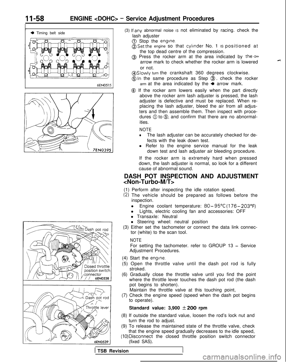
(3) lf
any abnormal noise IS not eliminated by racing. check the
lash adjuster
@ Stop the engine.
@ Set the engine so that cylinder
No. 1 IS positioned at
the top dead centre of the compression.
@ Press the rocker arm at the area indicated by the+
arrow mark to check whether the rocker arm is lowered
or not.
@ Slowly turn the crankshaft 360 degrees clockwise.
@ ln the same procedure as Step 0, check the rocker
arm at the area indicated by the
4 arrow mark.
@ If the rocker arm lowers easily when the part directly above the rocker arm lash adjuster is pressed, the lash
adjuster is defective and must be replaced. When re- placing the lash adjuster, bleed the air from all adjus-
ters and then assemble them. Then inspect with proce- dures
@I to 0, and confirm that there are no abnormal-
ities.
NOTE
lThe lash adjuster can be accurately checked for de-
fects with the leak down test.
l Refer to the engine service manual for the leak
down test and lash adjuster air bleeding procedure.
If the rocker arm is extremely hard when pressed
down, the lash adjuster is normal, so look for a different
cause of abnormal sound.
DASH POT INSPECTION AND ADJUSTMENT
(1) Perform after inspecting the idle rotation speed.
(2) The vehicle should be prepared as follows before the inspection.
l Engine coolant temperature:
80- 95°C
(176- 203°F)
lLights, electric cooling fan and accessories: OFF
l Transaxle: Neutral
l Steering wheel: neutral position
(3) Either set the tachometer or connect the data link connec- tor (white) to the scan tool.
NOTE
For setting the tachometer. refer to GROUP 13 - Service
Adjustment Procedures.
(4) Start the
engine.
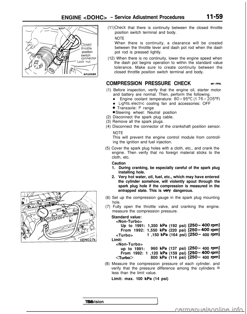
(5) Open the throttle valve until the dash pot rod is fully
stroked.
(6) Gradually close the throttle valve until you find the point where the throttle lever touches the dash pot rod (the dashpot begins to shorten).
Maintain the throttle valve at this touching point,
(7) Check the engine speed (speed when the dash pot begins to operate).
Standard value: 3,900
f 200 rpm
(8) If outside the standard value, loosen the rod’s lock nut and turn the rod to adjust.
(9) To release the maintained state of the throttle valve, check that the engine speed gradually decreases to the idle speed, (10)Disconnect
the closed throttle position switch connector
(fixed SAS).
1 TSB Revision
Page 109 of 1273
ENGINE
7 Go;;ikv position
switch
(11)Check that there is continuity between the closed throttle
position switch terminal and body.
NOTE
When there is continuity, a clearance will be created between the throttle lever and dash pot rod when the dash
pot rod is pressed lightly.
(12) When there is no continuity, lower the engine speed when the dash pot begins operation to within the standard value
tolerance. Make sure to create continuity between the
closed throttle position switch terminal and body.
COMPRESSION PRESSURE CHECK Ml 1 FFAL
(1) Before inspection, verify that the engine oil, starter motor
and battery are normal. Then, perform the following.
lEngine coolant temperature: 80- 95°C
(1 76- 205’F)
l Lights, electnc
cooling fan and accessories: OFF
0 Transaxle: P range 0 Steering wheel: Neutral position
(2) Disconnect the spark plug cable.
(3) Remove all the spark plugs.
(4) Disconnect the connector of the crankshaft position sensor.
NOTE
This will prevent the engine control module from controll- ing the ignition and fuel injection.
(5) Cover the spark plug holes with a cloth, etc., and crank the engine. Then verify that no foreign material sticks to the
cloth, etc.
Caution
1.During cranking, be especially careful of the spark plug
installing hole.
2. Very hot water, oil, fuel, etc., which may have entered
the cylinder somehow, will violently spout through the
spark plug hole if the compression is measured in the
entrapped state. This is
vex/ dangerous.
(6) Set up the compression gauge in the spark plug mounting
hole.
(7) Fully open the throttle valve, and cranking the engine.
measure the compression pressure.
Standard value:
kPa (192 psi) [250- 400 rpml
From 1992: 1,550
kPa (220 psi) [250-400 rpm]
Limit:
up to 1991: 960
kPa (137 psi) [250- 400 rpml
From 1992: 1 ,120 kPa (159 psi) [250- 400 rpml
CTurbo>
800
kPa (114 psi) [250- 400 rpml
(8) Measure the compression pressure of each cylinder. and verify that the pressure difference among the cylinders
is
less than the limit value.
Limit: max. 100
kPa (14 psi) TSB Revision
I