1989 MITSUBISHI GALANT cooling
[x] Cancel search: coolingPage 110 of 1273
II-60ENGINE
(9) If a cylinder’s compression pressure or pressure differenceis outside the limit, fill a small amount of engine oil through
the spark plug hole and repeat Items (7) and (8) above.
@ If the compression is increased when the oil is filled, the piston
and/or cylinder wall may be worn or
damaged.
@ If the compression is not Increased even though the oil is filled, the valve may be thermally seized, the valve
contact may be improper or pressure may leak at the
gasket. (10)Connect the connector of the crankshaft position sensor.
(1l)lnstall
the spark plug and spark plug cable.
(12)Erase the diagnostic trouble code with the scan tool or re-
connect the battery (-)
cable 10 seconds or more after it
was disconnected.
NOTE
This will erase the memory of the diagnostic trouble code which resulted from disconnection of the crankshaft posi-
tion sensor connector.
MANIFOLD VACUUM INSPECTION MllFNAD
(1) Before inspection and adjustment, put the vehicle into the following state.
l Engine coolant temperature:
85-95°C (185-205°F)
l Lights, motor cooling fan, and accessories: OFF
l Transaxle:
N (Neutral)
l Steering wheel: Neutral
(2) Check that the idling revolution speed is normal.
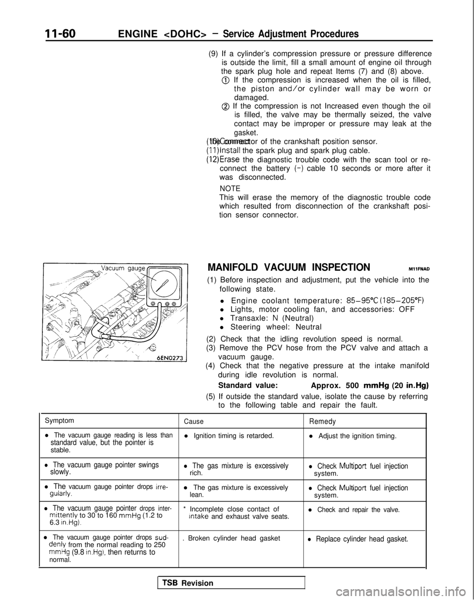
(3) Remove the PCV hose from the PCV valve and attach a
vacuum gauge.
(4) Check that the negative pressure at the intake manifold
during idle revolution is normal.
Standard value: Approx. 500 mmHg
(20 in.Hg)
(5) If outside the standard value, isolate the cause by referring to the following table and repair the fault.
Symptom
CauseRemedy
l The vacuum gauge reading is less thanstandard value, but the pointer isl Ignition timing is retarded. l Adjust the ignition timing.
stable.
l The vacuum gauge pointer swings
slowly.l The gas mixture is excessivelyrich.l Check Multiport fuel injectionsystem.
l The vacuum gauge pointer drops irre- gularly.
l The gas mixture is excessively
lean.l Check Multiport
fuel injectionsystem.
l The vacuum gauge pointer drops inter-mittently to 30 to 160 mmHg
(1.2 to * Incomplete close contact of Intake
and exhaust valve seats.l Check and repair the valve.
6.3 in.Hg).
l The vacuum gauge pointer drops sud- denly
from the normal reading to 250 . Broken cylinder head gasketl Replace cylinder head gasket.
mmHg (9.8 in.Hg), then returns tonormal.
TSB Revision
Page 174 of 1273
13-32
FUEL SYSTEM
FUEL TANK AND FUEL LINEMlBEAAA
Symptom Probable cause Remedy
Engtne malfunctions
Bent or kinked fuel pipe or hose Repair or replace3ue to insufficient fuel
SUPPlYClogged fuel pipe or hoseClean or replace
Clogged fuel filter or in-tank fuel filter Replace
Water in fuel filter Replace the fuel filter or clean the fuel tank
and fuel line
Dirty or rusted fuel tank interior Malfunctioning fuel pump
(Clogged filter in the pump) Clean or replace
Replace
Evaporative emission Mispiping of vapor line
Correct
control system malfunc-
tions (When fuel tank Disconnect vapor line piping joint Correct
filler tube cap is re- moved, pressure releas-
Folded, bent, cracked or clogged vapor line Replace
ng noise is heard) Faulty fuel tank filler tube cap
Malfunctioning fuel tank pressure control
valve Replace
Replace
LL
m ~~ : Paper clip-
F l!;“I /yFp- -
izd--_7-01
A0086SERVICE ADJUSTMENT PROCEDURES
CURB IDLE SPEED INSPECTION
MlBFHAFt
(1) The vehicle should be prepared as follows before the inspection.
lEngine coolant temperature: 85-95°C (185-203°F)
l Lights, electric cooling fan and accessories: OFF
l Transaxle: Neutral
(P for vehicles with an automatic
transaxle)
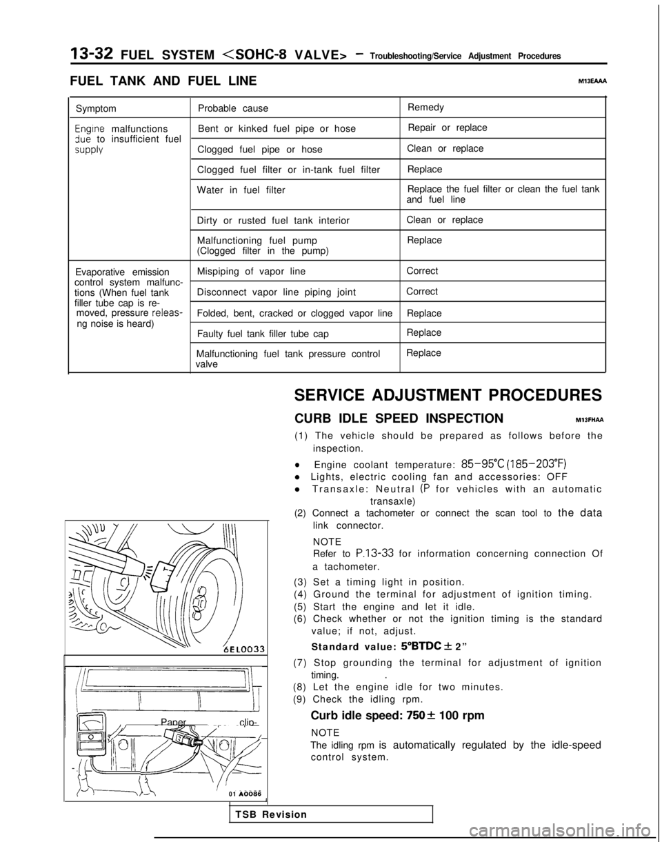
(2) Connect a tachometer or connect the scan tool to the data
link connector.
NOTE
Refer to
P.13-33 for information concerning connection Of
a tachometer.
(3) Set a timing light in position.
(4) Ground the terminal for adjustment of ignition timing.
(5) Start the engine and let it idle.
(6) Check whether or not the ignition timing is the standard
value; if not, adjust.
Standard value:
5”BTDC + 2”
(7) Stop grounding the terminal for adjustment of ignition timing. .
(8) Let the engine idle for two minutes.
(9) Check the idling rpm.
Curb idle speed:
7502 100 rpm
NOTE
The idling rpm is automatically regulated by the idle-speed control system.
1
TSB Revision
Page 175 of 1273
FUEL SYSTEM
For a female
pin
For a male pin
(insert at side (Insert at lock tab side.,
opposite from lock tab.)
OlLO246
(10)lf not within the standard value range, refer to the CHECK
CHART CLASSIFIED BY PROBLEM SYMPTOMS and check the
MFI component.
BASIC IDLE SPEED ADJUSTMENT
MlBFHBA
(1) The vehicle should be prepared as follows before the inspection and adjustment.
l Engine coolant temperature:
85-95°C (185-205°F)
l Lights, electric cooling fan and accessories: OFF
l Transaxle: Neutral
(P for vehicles with an automatic
transaxle)
(2) Slacken the accelerator cable enough.
(3) Connect the scan tool to the data link connector (white).
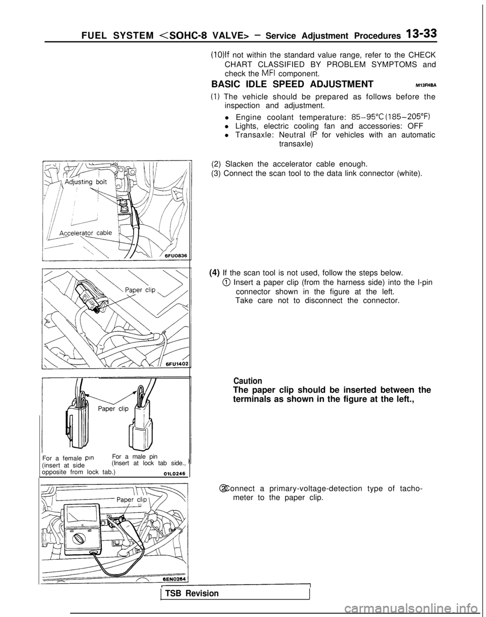
(4) If the scan tool is not used, follow the steps below.
@I Insert a paper clip (from the harness side) into the l-pin connector shown in the figure at the left.
Take care not to disconnect the connector.
Caution
The paper clip should be inserted between the
terminals as shown in the figure at the left., @ Connect a primary-voltage-detection type of tacho-
meter to the paper clip.
TSB Revision
Page 192 of 1273
13-50 FUEL SYSTEM
INSPECTION
Using Scan Tool
Item No. Data display Inspection conditions
12Sensor de-
tection air
volume (fre-
quency) . Engine coolant
temperature: 85-95°C(185-205°F). Lights, cooling fan, elec-
trical accessories: OFF
. Transaxle: neutral (iVT
models: “P” range)
RacingFrequency in-
creases as racing
rpm increases.
NOTEThe volume air flow sensor output frequency may be about 10% higher than\
indicated above when the vehicle is new [driven approximately 500 km (300 miles) or less].
Regular waveform 03A0203
HARNESS INSPECTION
@
Harness sideconnector
6
0-0
~
0
=
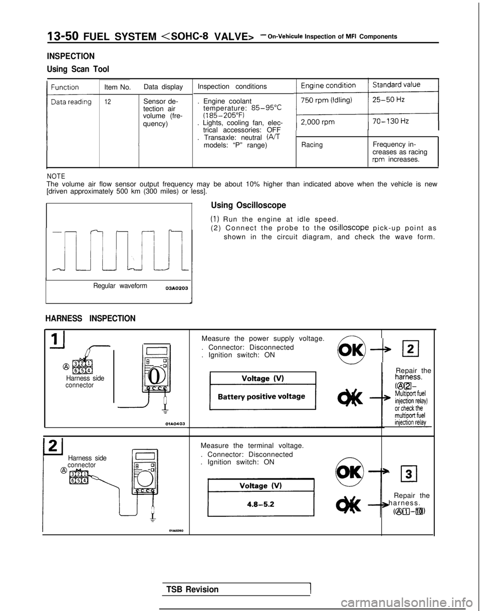
Using Oscilloscope
(1) Run the engine at idle speed.
(2) Connect the probe to the
osilloscope pick-up point a
s
shown in the circuit diagram, and check the wave form.
Measure the power supply voltage.
. Connector: Disconnected
. Ignition switch: ON
--P
IRepair the
Harness sideconnector
Measure the terminal voltage.
. Connector: Disconnected
. Ignition switch: ON ~
0
OK’ 30
Repair the
harness
.
cm-an)
TSB Revision1
Page 207 of 1273
FUEL SYSTEM
(1) Improper adjustment of the basic idling speed.
(2) Deposits adhering to the ttirottle valve.
(3) Air being taken into the intake manifold due to a gasket leak, etc.
OPERATION
ISC motor position sensor is a variable resistor type,
and is integrated in the
ISC motor system. The slid-
ing pin of
ISC motor position sensor is in contact
with the end of the plunger. Therefore, as the plun- ger moves, the internal resistance of
ISC motor pos-
ition sensor varies. This leads to the variation of the (4) Improper seating of the EGR valve seat.
(5) lmcomplete combustion within a cylinder. (Mal-
function of spark plugs, ignition coil, injectors,
compression pressure, etc.)
the plunger position of the
ISC motor system, and
sends the signal to ECM. ECM processes the
ISC
motor position sensor signal, idle signal, coolant
temperature signal, load signal (A/T &
A/C) and ve-
hicle speed signal to control the opening angle of
the throttle valve and revolution speed during
en-
output voltage. ISC motor position sensor detects gine idling.
TROUBLESHOOTING HINTS
Since idling is not controlled when ISC motor posi-
tion sensor is troubled, idling may not be evenly
maintained.
INSPECTION
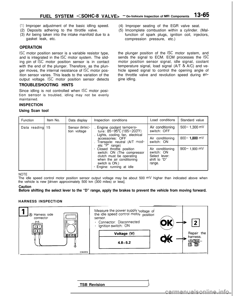
Using Scan tool
FunctionItem No. Data display Inspection conditions Load conditions
Standard value
Data reading 15 Sensor detec-
. Engine coolant tempera-
Air conditioning 500- 1,300 mV
tion voltage
ture: 85-95’C (185-203°F)
switch: OFF
. Lights, cooling fan, electrical accessories: OFF Air conditioning 800-
1,800 mV. Transaxle: neutral (A/T
mod-
switch: ON
els: “P”
range)
1 Closed throttle position Air conditioning900- 1,900 mVswitch: ON (The compressorswitch: ON
clutch must be operating Select lever:
when the air conditioning shift to “D”
switch is ON.)
range.* Engine: running at idle
NOTEThe idle speed control motor position sensor output voltage may be about\
500 mV higher than indicated above when
the vehicle is new [driven approximately 500 km (300 miles) or less].
CautionBefore shifting the select lever to the “D” range, apply the brake\
s to prevent the vehicle from moving forward.
HARNESS INSPECTION
Measure the power supply voltage of
the idle speed control motor position
ei;;;it;;sco$ected
__...._ -.-
TSB Revision
Page 233 of 1273
FUEL SYSTEM
Inspection of MFI Components13-91
INSPECTION
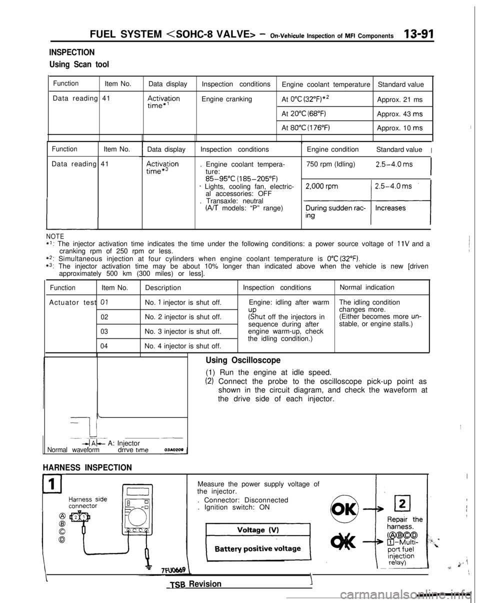
Using Scan tool
FunctionItem No. Data display
Data reading 41
III~~~ion
Inspection conditions Engine coolant temperature Standard value
Engine cranking At
0°C (3~2°F)“~Approx. 21 ms
At
20°C (68°F)Approx. 43 ms
At
80°C (176°F)Approx. 10 ms
FunctionItem No.
Data reading 41
L
Data display
Ac&a$ion
Inspection conditions
. Engine coolant tempera- ture:
85-95°C (185-205°F)* Lights, cooling fan, electric-al accessories: OFF
. Transaxle: neutral
(A/T models: “P” range) Engine condition
Standard value
I
750 rpm (Idling)2.5-4.0 ms
I
NOTE*I: The injector activation time indicates the time under the following con\
ditions: a power source voltage of 11V and a
cranking rpm of 250 rpm or less.
**: Simultaneous injection at four cylinders when engine coolant temperatur\
e is 0°C (32°F).*3: The injector activation time may be about 10% longer than indicated abo\
ve when the vehicle is new [driven approximately 500 km (300 miles) or less].
FunctionItem No.
Actuator test
01
02
03
04
Description
No.
1 injector is shut off.
No. 2 injector is shut off.
No. 3 injector is shut off.
No. 4 injector is shut off. Inspection conditions
Normal indication
Engine: idling after warm The idling condition
changes more.
r”sput off the injectors in(Either becomes more un-sequence during after stable, or engine stalls.)
engine warm-up, check
the idling condition.)
-
I i-. --.-~-db$- A: Injector~__
Normal waveformdrrve time
HARNESS INSPECTION
1
P
Using Oscilloscope
(1) Run the engine at idle speed.
(2) Connect the probe to the oscilloscope pick-up point as
shown in the circuit diagram, and check the waveform at
the drive side of each injector.
Measure the power supply voltage of
the injector.
. Connector: Disconnected. Ignition switch: ON
TSB Revision
I
I
4
i1
k ji,v,11
\
YIY’.
Page 275 of 1273

FUEL SYSTEM
FUEL TANK AND FUEL LINEMIBEAAB
Symptom
Probable cause Remedy
Engine malfunctions
due to insufficient
fuel supply Bent or kinked fuel pipe or hose
Clogged fuel pipe or hose
Clogged fuel filter or in-tank fuel filter
Water in fuel filter Repair or replace
Clean or replace
Replace
Replace the fuel filter or clean the
fuel tank and fuel line
Dirty or rusted fuel tank interior
Clean or replace
Malfunctioning fuel pump
(Clogged filter in the pump)Replace
Evaporative emission
control system
malfunctions
[When fuel tank filler
tube cap is removed,
pressure releasingnoise is heard) Mispiping of vapor line
Disconnected vapor line piping joint
Folded, bent, cracked or clogged vapor line
Faulty fuel tank filler tube cap
Malfunctioning fuel tank pressure control valve Correct
Correct
Replace
Replace
Replace
SERVICE ADJUSTMENT
PROCEDURES
CURB IDLE SPEED INSPECTIONhll3MAE
(1) The vehicle should be prepared as follows before th
e
inspection.
lEngine coolant temperature: 85-95°C (185-203°F)
l Lights, electric cooling fan and accessories: OFF
l Transaxle: Neutral (P for vehicles with an automatic
transaxle)
(2) Connect a tachometer.
NOTE
Refer to
P.13-134 for information concerning connection Of
a tachometer.
(3) Set a timing light in position.
(4) Ground the terminal for adjustment of ignition timing.
(5) Start the engine and let it idle.
(6) Check whether or not the ignition timing is the standard
value; if not, adjust.
Standard value:
5”BTDC f 2”
(7) Stop grounding the terminal for adjustment of ignition timing.
(8) Let the engine idle for two minutes.
(9) Check the idling rpm.
Curb idle speed: 700
31100 rpm
NOTE
The idling rpm is automatically regulated by the idle aircontrol system.
(lO)lf not within the standard value range, refer to the CHECK
CHART CLASSIFIED BY PROBLEM SYMPTOMS and check
the
MFI component,
TS6 Revision1
Page 276 of 1273
13-134FUEL SYSTEM (SOHC-16 VALVE> -Service Adjustment Procedures
BASIC IDLE SPEED ADJUSTMENTMlIFHBX
NOTE
1. The standard idling speed has been adjusted, by the en-
gine speed adjusting screw, by the manufacturer, and
there should usually be no need for readjustment.
2. Use the following procedure to adjust when the idling speed drops due to an incorrect adjustment, high idling
speed, or when a load such as the air conditioning is ap-
plied on the engine.
3. The adjustment, if made, should be made after first con- firming that the spark plugs, the injectors, the idle air con-
trol motor, the compression pressure, etc. are all normal.
(I ) The vehicle should be prepared as follows before the inspec- tion and adjustment.
l Engine coolant temperature:
85-95°C (185-203°F)
l Lights, cooling fan and accessories: OFF
l Transaxle: neutral (A/T for
P range)
l Steering wheel: neutral position
(2) Connect the scan tool to the data link connector (white).
NOTE
When the scan tool is connected, the diagnostic test mode control terminal should be grounded.
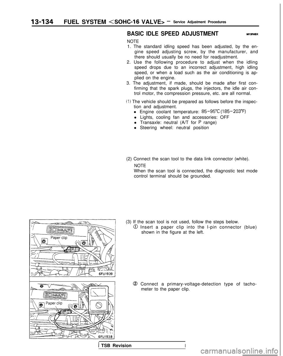
(3) If the scan tool is not used, follow the steps below.
@I Insert a paper clip into the l-pin connector (blue) shown in the figure at the left.
0 Connect a primary-voltage-detection type of tacho-meter to the paper clip.
1 TSB RevisionI