1989 MITSUBISHI GALANT lock
[x] Cancel search: lockPage 83 of 1273
ENGINE
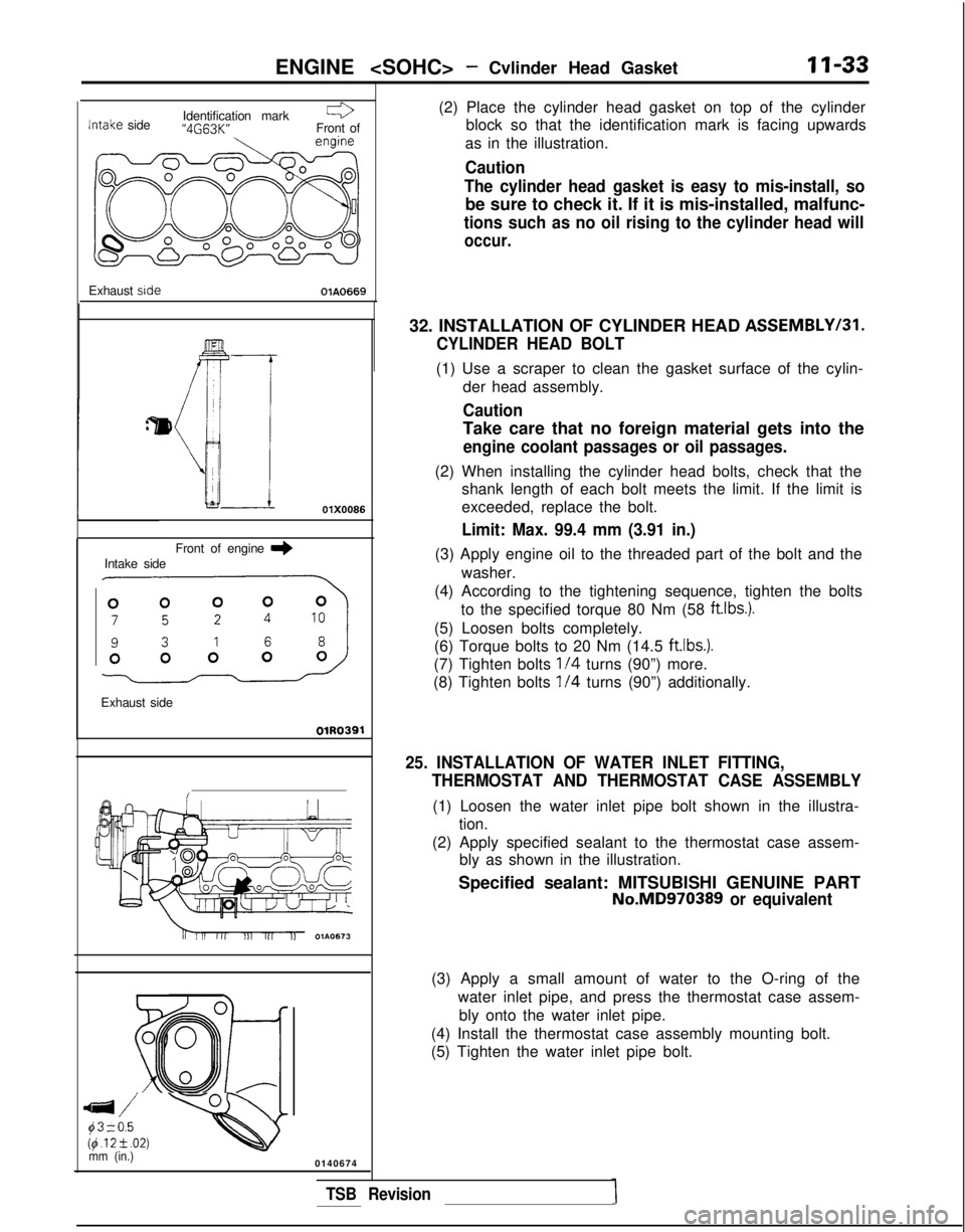
Identification markr3
Intake
side “4G63K”
Front of
Exhaust side
OlA0669
Front of engine
I)Intake side
Exhaust side
OlR0391
Ei;. -Qmm (in.)0140674 (2) Place the cylinder head gasket on top of the cylinder
block so that the identification mark is facing upwards
as in the illustration.
Caution
The cylinder head gasket is easy to mis-install, so
be sure to check it. If it is mis-installed, malfunc-
tions such as no oil rising to the cylinder head will
occur.
32. INSTALLATION OF CYLINDER HEAD ASSEMBLYI31.
CYLINDER HEAD BOLT
(1) Use a scraper to clean the gasket surface of the cylin-
der head assembly.
Caution
Take care that no foreign material gets into the
engine coolant passages or oil passages.
(2) When installing the cylinder head bolts, check that theshank length of each bolt meets the limit. If the limit is
exceeded, replace the bolt.
Limit: Max. 99.4 mm (3.91 in.)
(3) Apply engine oil to the threaded part of the bolt and the
washer.
(4) According to the tightening sequence, tighten the bolts to the specified torque 80 Nm (58 ftlbs.).
(5) Loosen bolts completely.
(6) Torque bolts to 20 Nm (14.5
ft.lbs.).
(7) Tighten bolts l/4 turns (90”) more.
(8) Tighten bolts
l/4 turns (90”) additionally.
25. INSTALLATION OF WATER INLET FITTING, THERMOSTAT AND THERMOSTAT CASE ASSEMBLY
(1) Loosen the water inlet pipe bolt shown in the illustra-tion.
(2) Apply specified sealant to the thermostat case assem- bly as shown in the illustration.
Specified sealant: MITSUBISHI GENUINE PART
No.MD970389 or equivalent
(3) Apply a small amount of water to the O-ring of the
water inlet pipe, and press the thermostat case assem-bly onto the water inlet pipe.
(4) Install the thermostat case assembly mounting bolt.
(5) Tighten the water inlet pipe bolt.
TSB Revision
Page 86 of 1273
11-36
ENGINE
Timing mark
\
Camshaft sprocket
;/
i
\
IlEN0017
Tit
e
I;
OlAO550
01A0551
SERVICE POINTS OF REMOVALMllKBDF
2. REMOVAL OF ENGINE MOUNT BRACKET
(1) Jack up the vehicle after placing a wooden block
between the jack and the engine’s oil pan.
Caution
Jack up carefully so as not to apply an excessive
load to the various parts.
(2) Remove the engine mount bracket.
20. REMOVAL OF TIMING BELT
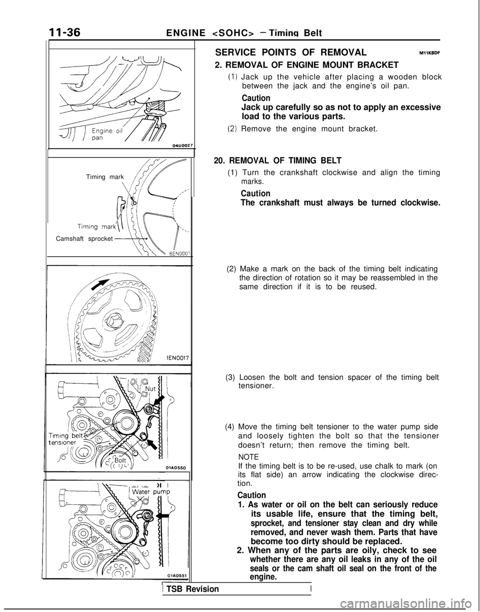
(1) Turn the crankshaft clockwise and align the timing
marks.
Caution
The crankshaft must always be turned clockwise.
(2) Make a mark on the back of the timing belt indicating the direction of rotation so it may be reassembled in the
same direction if it is to be reused.
(3) Loosen the bolt and tension spacer of the timing belt tensioner.
(4) Move the timing belt tensioner to the water pump side and loosely tighten the bolt so that the tensioner
doesn’t return; then remove the timing belt.
NOTE
If the timing belt is to be re-used, use chalk to mark (on
its flat side) an arrow indicating the clockwise direc-
tion.
Caution
1. As water or oil on the belt can seriously reduce
its usable life, ensure that the timing belt,
sprocket, and tensioner stay clean and dry while
removed, and never wash them. Parts that have
become too dirty should be replaced.
2. When any of the parts are oily, check to see
whether there are any oil leaks in any of the oil
seals or the cam shaft oil seal on the front of the
engine.
1 TSB Revision
Page 87 of 1273
ENGINE
-
u
w
rack
rack
Separ
Crack’
7EN207
Rounded belt side
Abnormal wear (fluffy canvas fiber)
7EN20E-1 TSB Revision 22. REMOVAL OF OIL PUMP SPROCKET
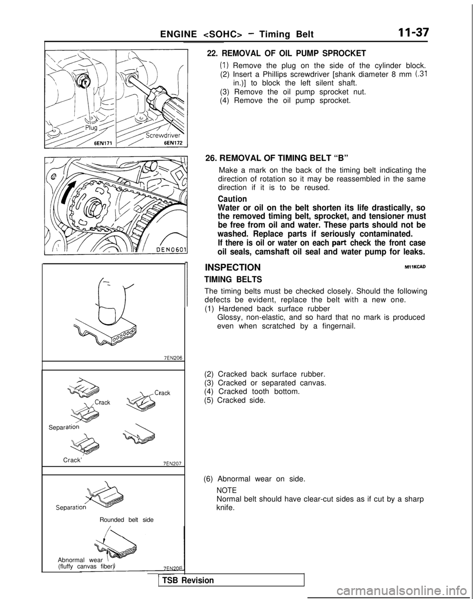
(1) Remove the plug on the side of the cylinder block.
(2) Insert a Phillips screwdriver [shank diameter 8 mm
(.31
in.)] to block the left silent shaft.
(3) Remove the oil pump sprocket nut.
(4) Remove the oil pump sprocket.
26. REMOVAL OF TIMING BELT “B” Make a mark on the back of the timing belt indicating the
direction of rotation so it may be reassembled in the same
direction if it is to be reused.
Caution
Water or oil on the belt shorten its life drastically, so
the removed timing belt, sprocket, and tensioner must be free from oil and water. These parts should not be
washed. Replace parts if seriously contaminated.
If there is oil or water on each part check the front case
oil seals, camshaft oil seal and water pump for leaks.
INSPECTIONMIlKCAD
TIMING BELTS
The timing belts must be checked closely. Should the following defects be evident, replace the belt with a new one.
(1) Hardened back surface rubber Glossy, non-elastic, and so hard that no mark is produced
even when scratched by a fingernail.
(2) Cracked back surface rubber.
(3) Cracked or separated canvas.
(4) Cracked tooth bottom.
(5) Cracked side.
(6) Abnormal wear on side.
NOTE
Normal belt should have clear-cut sides as if cut by a sharp
knife.
Page 90 of 1273
II-40ENGINE
OlRO372
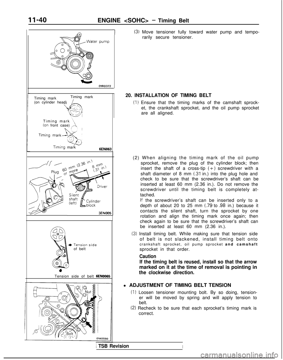
1(3) Move tensioner fully toward water pump and tempo-rarily secure tensioner.
Timing mark Timing mark
(on cylinder head)
Timing mark
“1(on front case) ,A.
Timing mark6EN063
3ENOO5
Tensiorof belt-I sid
e
Tension side of belt
6EN0065
20. INSTALLATION OF TIMING BELT
(1) Ensure that the timing marks of the camshaft sprock- et, the crankshaft sprocket, and the oil pump sprocket
are all aligned.
(2) When aligning the timing mark of the oil pump sprocket, remove the plug of the cylinder block; then
insert the shaft of a cross-tip
(+) screwdriver with a
shaft diameter of 8 mm
(.31 in.) into the plug hole and
check to be sure that the screwdriver’s shaft can be
inserted at least 60 mm (2.36 in.). Do not remove the
screwdriver until the timing belt is completely at-
tached.
If the screwdriver’s shaft can be inserted only to a
depth of about 20 to 25 mm
(.79 to .98 in.) because it
contacts the silent shaft, turn the sprocket by one rotation and align the timing mark once again; then
check again to be sure that the screwdriver’s shaft can be inserted at least 60 mm (2.36 in.).
(3) Install timing belt. While making sure that tension side
of belt is not slackened, install timing belt onto
crankshaft sprocket, oil pump sprocket and camshaf
t
sprocket in that order.
Caution
If the timing belt is reused, install so that the arrow
marked on it at the time of removal is pointing in
the clockwise direction.
l ADJUSTMENT OF TIMING BELT TENSION
(1) Loosen tensioner mounting bolt. By so doing, tension- er will be moved by spring and will apply tension to
belt.
(2) Recheck to be sure that each sprocket’s timing mark iscorrect.
1 TSB RevisionI
Page 91 of 1273
ENGINE
I
I
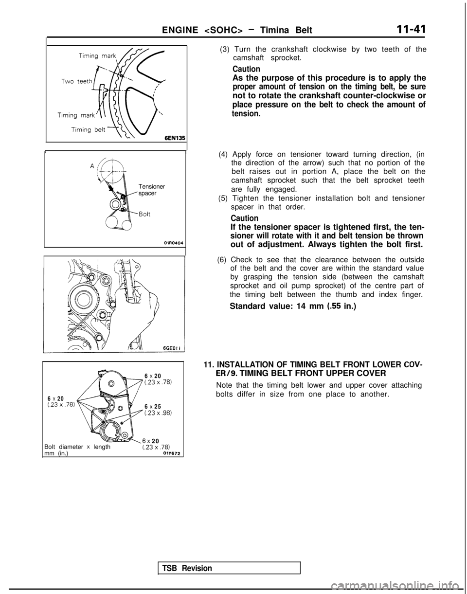
(3) Turn the crankshaft clockwise by two teeth of the
camshaft sprocket.
Caution
As the purpose of this procedure is to apply the
proper amount of tension on the timing belt, be sure
not to rotate the crankshaft counter-clockwise or
place pressure on the belt to check the amount of
tension.
Tensioner
spacer
OlR0404
(4) Apply force on tensioner toward turning direction, (inthe direction of the arrow) such that no portion of the
belt raises out in portion A, place the belt on the
camshaft sprocket such that the belt sprocket teeth
are fully engaged.
(5) Tighten the tensioner installation bolt and tensioner spacer in that order.
Caution
If the tensioner spacer is tightened first, the ten-
sioner will rotate with it and belt tension be thrown
out of adjustment. Always tighten the bolt first.
TSB Revision
(6) Check to see that the clearance between the outside of the belt and the cover are within the standard value
by grasping the tension side (between the camshaft
sprocket and oil pump sprocket) of the centre part of
the timing belt between the thumb and index finger.
Standard value: 14 mm
(.55 in.)
6 x 20(23 x .78)
6 x 20(23 x .78)
6 x 25t.23 x ,981
11. INSTALLATION OF TIMING BELT FRONT LOWER COV- ER/9.
TIMING BELT FRONT UPPER COVER
Note that the timing belt lower and upper cover attaching
bolts differ in size from one place to another.
Bolt diameter
x length
mm (in.)6x 20t.23 x ,781011672
Page 94 of 1273
ENGINE
A Timing
mark
Timingmark
mark
-/Crank&aft swocketOlA0667 lEN0017SERVICE POINTS OF REMOVAL
MllKBDG
2. REMOVAL OF ENGINE MOUNT BRACKET
(1) With a wooden block placed against the oil pan part ofthe engine, jack up the vehicle.
Caution
Jack up gently, so as not to apply a load to the va-
rious parts.
(2) Remove the engine mount bracket.
11. REMOVAL OF AUTO TENSIONER
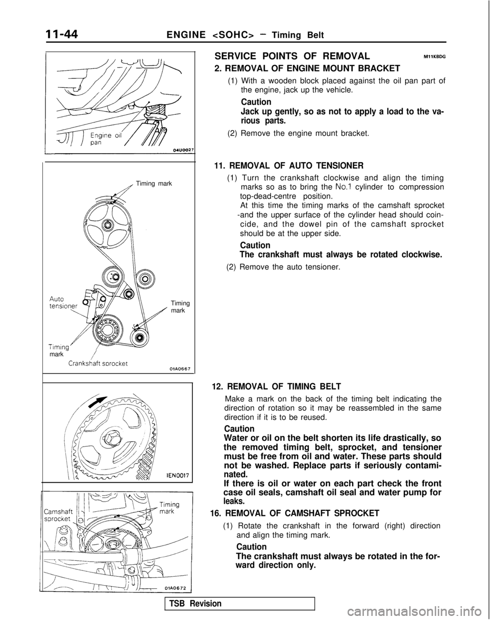
(1) Turn the crankshaft clockwise and align the timing marks so as to bring the
No.1 cylinder to compression
top-dead-centre position. At this time the timing marks of the camshaft sprocket
-and the upper surface of the cylinder head should coin- cide, and the dowel pin of the camshaft sprocket
should be at the upper side.
Caution
The crankshaft must always be rotated clockwise.
(2) Remove the auto tensioner.
12. REMOVAL OF TIMING BELT
Make a mark on the back of the timing belt indicating the
direction of rotation so it may be reassembled in the same
direction if it is to be reused.
Caution
Water or oil on the belt shorten its life drastically, so
the removed timing belt, sprocket, and tensioner must be free from oil and water. These parts should
not be washed. Replace parts if seriously contami-
nated.
If there is oil or water on each part check the front
case oil seals, camshaft oil seal and water pump for
leaks.
16. REMOVAL OF CAMSHAFT SPROCKET
(1) Rotate the crankshaft in the forward (right) direction
and align the timing mark.
Caution
The crankshaft must always be rotated in the for-
ward direction only.
TSB Revision
Page 95 of 1273
ENGINE
11-45
sprocket
vlGVO001 MD998754
vlB990767-01
-
&
00B00°
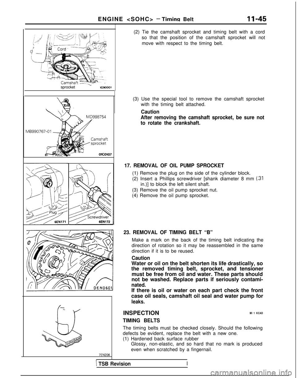
(2) Tie the camshaft sprocket and timing belt with a cord
so that the position of the camshaft sprocket will not
move with respect to the timing belt.
(3) Use the special tool to remove the camshaft sprocket with the timing belt attached.
Caution
After removing the camshaft sprocket, be sure not
to rotate the crankshaft.
17. REMOVAL OF OIL PUMP SPROCKET
(1) Remove the plug on the side of the cylinder block.
(2) Insert a Phillips screwdriver [shank diameter 8 mm
(31
in.)] to block the left silent shaft.
(3) Remove the oil pump sprocket nut.
(4) Remove the oil pump sprocket.
23. REMOVAL OF TIMING BELT “B”
Make a mark on the back of the timing belt indicating the
direction of rotation so it may be reassembled in the same
direction if it is to be reused.
Caution
Water or oil on the belt shorten its life drastically, so
the removed timing belt, sprocket, and tensioner
must be free from oil and water. These parts should
not be washed. Replace parts if seriously contami-
nated.
If there is oil or water on each part check the front
case oil seals, camshaft oil seal and water pump for
leaks.
INSPECTIONMl 1 KCAD
TIMING BELTS
The timing belts must be checked closely. Should the following
defects be evident, replace the belt with a new one.
(1) Hardened back surface rubber Glossy, non-elastic, and so hard that no mark is produced
even when scratched by a fingernail.
\ TSB RevisionI
Page 100 of 1273
ENGINE
Center bolt i\ \
6EN028:
Timina mark
Timingmark
Timing mark
Crankshaft sprocket
OlAO668
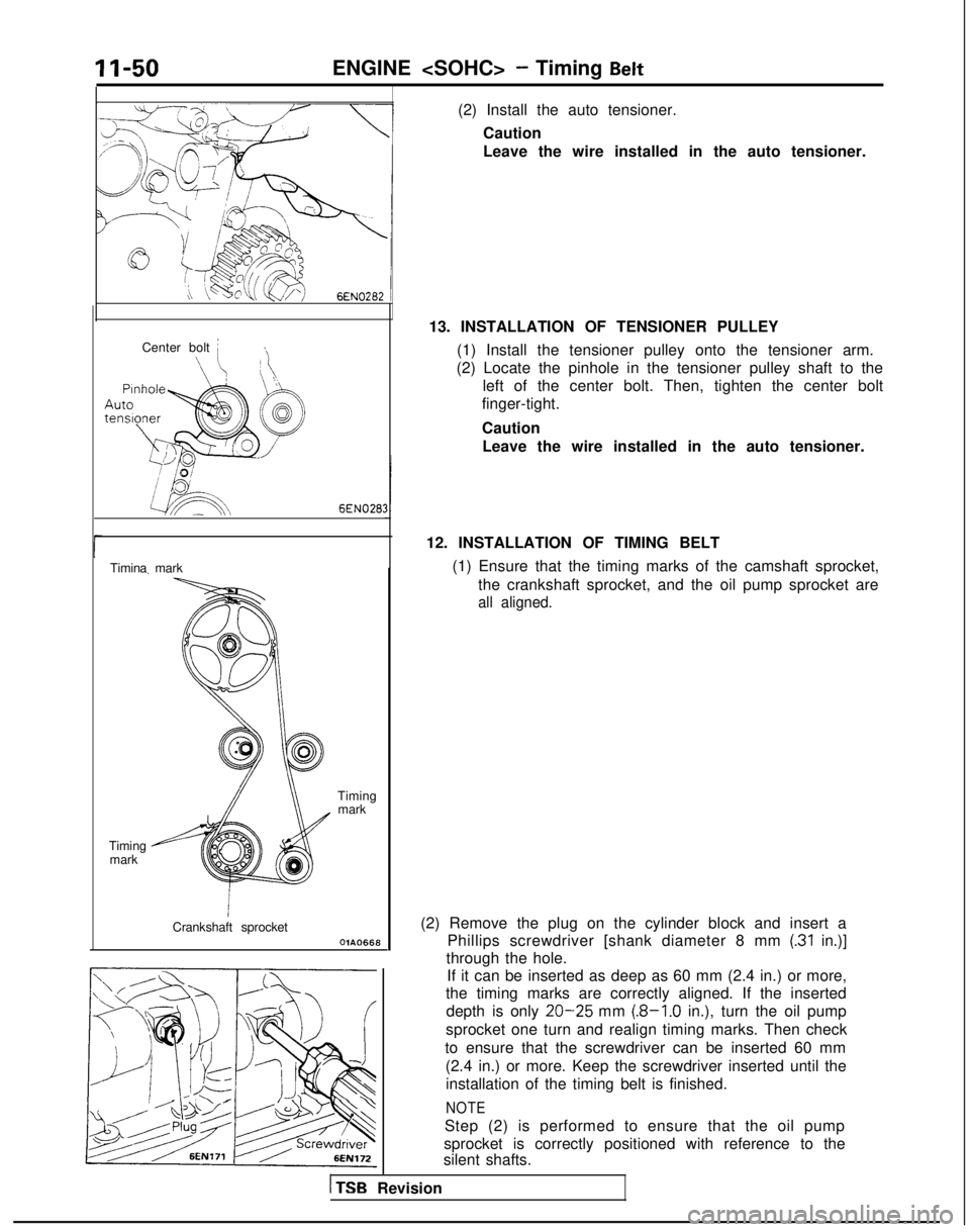
(2) Install the auto tensioner.Caution
Leave the wire installed in the auto tensioner.
13. INSTALLATION OF TENSIONER PULLEY (1) Install the tensioner pulley onto the tensioner arm.
(2) Locate the pinhole in the tensioner pulley shaft to the left of the center bolt. Then, tighten the center bolt
finger-tight.
Caution
Leave the wire installed in the auto tensioner.
12. INSTALLATION OF TIMING BELT (1) Ensure that the timing marks of the camshaft sprocket,the crankshaft sprocket, and the oil pump sprocket are
all aligned.
(2) Remove the plug on the cylinder block and insert a Phillips screwdriver [shank diameter 8 mm
(.31 in.)]
through the hole. If it can be inserted as deep as 60 mm (2.4 in.) or more,
the timing marks are correctly aligned. If the inserted
depth is only
20-25 mm (.8-1.0 in.), turn the oil pump
sprocket one turn and realign timing marks. Then check
to ensure that the screwdriver can be inserted 60 mm (2.4 in.) or more. Keep the screwdriver inserted until theinstallation of the timing belt is finished.
NOTE
Step (2) is performed to ensure that the oil pump
sprocket is correctly positioned with reference to the
silent shafts.
1 TSB Revision