1989 MITSUBISHI GALANT water pump
[x] Cancel search: water pumpPage 130 of 1273
II-80ENGINE
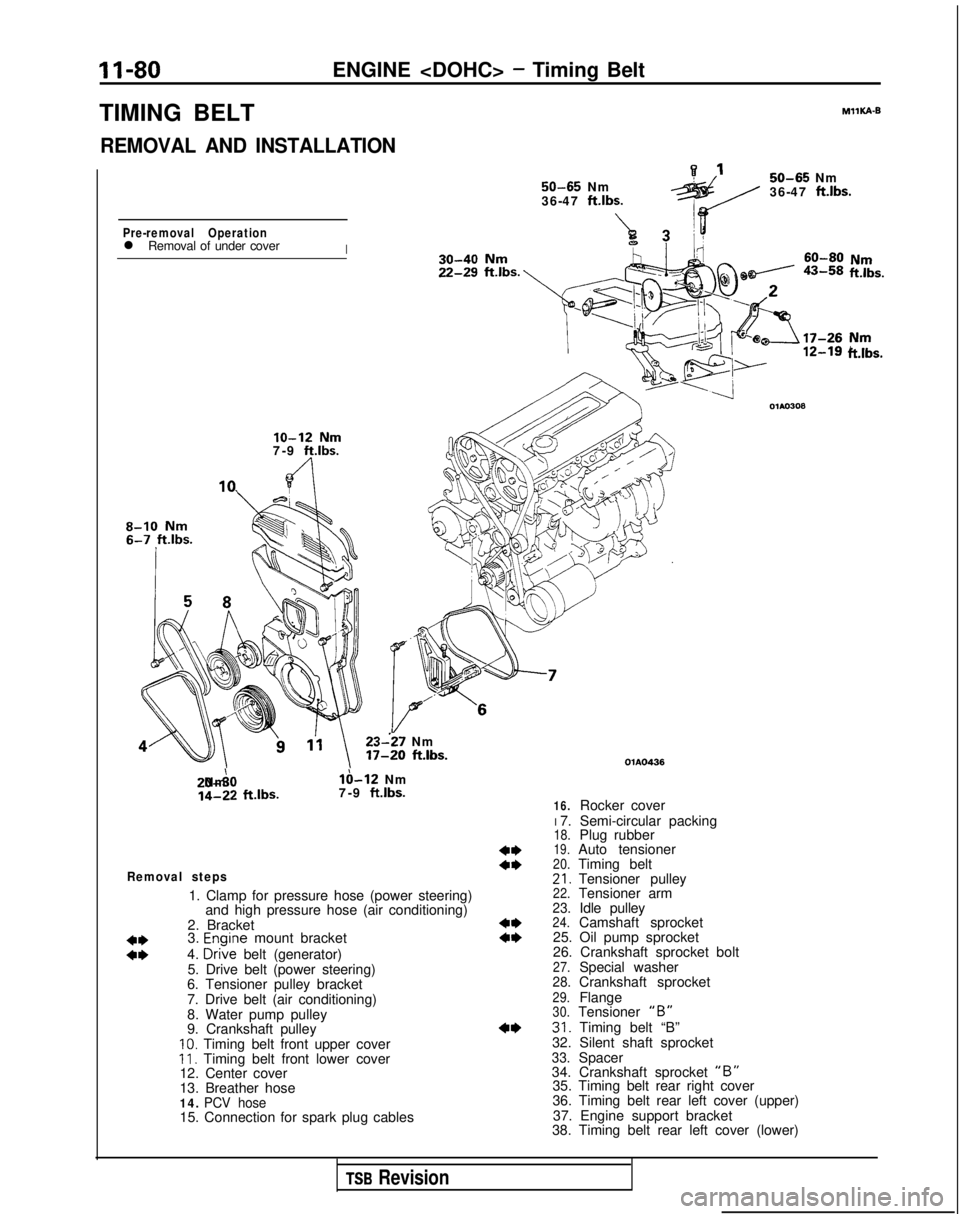
TIMING BELT
REMOVAL AND INSTALLATION 50-65
Nm
36-47 ftlbs.
A7Pre-removal Operationl Removal of under coverI MIlKA-B
50-65
Nm
36-47
ft.lbs.
ii!&.
lo-12 Nm7-9 ft.lbs.
8-10 Nm
23--27 Nm 17-20
ft.lbs. 20-A0 Nm
lb-12 Nm
14-22
ftlbs.
7-9 ft.lbs.
Removal steps
1. Clamp for pressure hose (power steering)
and high pressure hose (air conditioning)
2. Bracket
3.
Enoine mount bracket
ii4. D&e belt (generator)
5. Drive belt (power steering)
6. Tensioner pulley bracket
7. Drive belt (air conditioning)
8. Water pump pulley
9. Crankshaft pulley
10. Timing belt front upper coverII. Timing belt front lower cover
12. Center cover
13. Breather hose
14. PCV hose15. Connection for spark plug cables
ft.lbs.
4*a*
4**I)
4* OlAO436
16.Rocker cover
I 7. Semi-circular packing
18.Plug rubber19.Auto tensioner20.Timing belt21.Tensioner pulley22.Tensioner arm23.Idle pulley24.Camshaft sprocket
25. Oil pump sprocket
26. Crankshaft sprocket bolt
27.Special washer28.Crankshaft sprocket29.Flange30.Tensioner “B”31. Timing belt “B”
32. Silent shaft sprocket
33.Spacer
34. Crankshaft sprocket “B”35. Timing belt rear right cover
36. Timing belt rear left cover (upper)
37. Engine support bracket
38. Timing belt rear left cover (lower)
TSB Revision
Page 131 of 1273
ENGINE
f”.53A51b;m
r----v 1
3
lo-12 Nm
11-16
ftlbs.80-100
Nm y~x-di
58-72ft.lbs.2234!?!I
212543-55Nm 31-40, ff.lbs.b&-.,\‘-
/20-27 Nm
14-20
ftlbs.110;130 Nm80-94
ftlbs.
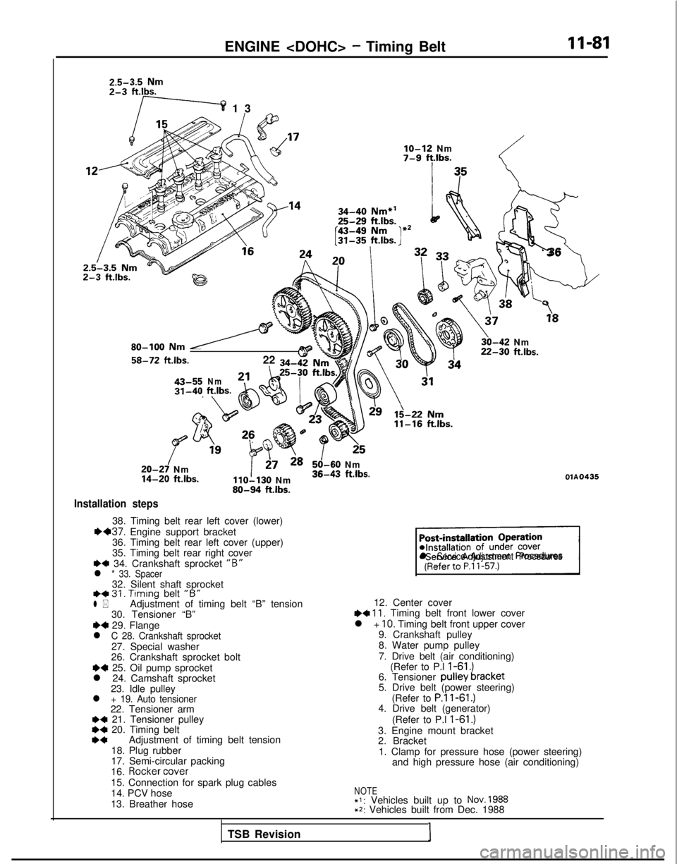
Installation steps
38. Timing belt rear left cover (lower)1H37. Engine support bracket
36. Timing belt rear left cover (upper)
35. Timing belt rear right cover
+4 34. Crankshaft sprocket “B”l * 33. Spacer32. Silent shaft sprocketI)+ 31. Timing
belt “B”l *Adjustment of timing belt “B” tension
30. Tensioner “B”
~~ 29. Flangel C 28. Crankshaft sprocket27. Special washer
26. Crankshaft sprocket bolt
~~ 25. Oil pump sprocket
l 24. Camshaft sprocket 23. Idle pulley
l + 19. Auto tensioner22. Tensioner arm+a 21. Tensioner pulley*C 20. Timing beltI)*Adjustment of timing belt tension
18. Plug rubber
17. Semi-circular packing
16.
Rocker cover
15. Connection for spark plug cables
14. PCV hose
13. Breather hose
!_-;
‘3
6
\
3,“”
30-42 Nm22-30 ftlbs.
125
50-60 Nm36-43 ftlbs.OlA0435
sl Service Adjustment Procedures
12. Center cover~~ 11, Timing belt front lower cover
l + IO. Timing belt front upper cover
9. Crankshaft pulley
8. Water pump pulley
7. Drive belt (air conditioning) (Refer to P.l
I-61 .)6. Tensioner pulley bracket
5. Drive belt (power steering)
(Refer to
P.ll-61.)4. Drive belt (generator)
(Refer to P.l
I-61 .)3. Engine mount bracket
2. Bracket1. Clamp for pressure hose (power steering) and high pressure hose (air conditioning)
NOTE+I: Vehicles built up to NOV. 1988+2: Vehicles built from Dec. 1988
TSB Revision I
Page 132 of 1273
II-82
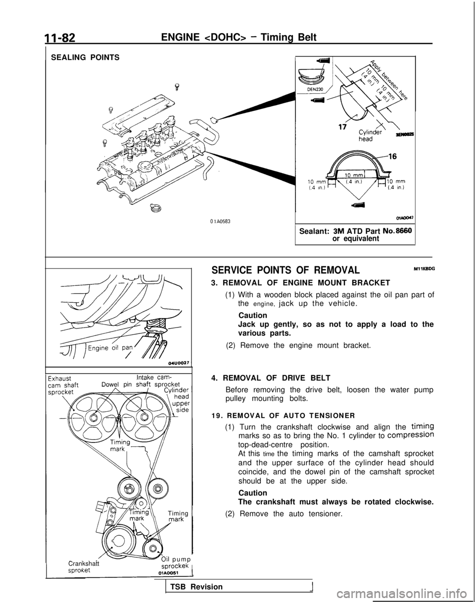
SEALING POINTSENGINE
- Timing Belt
olaoo4~
0 1 A0583
Sealant: 3M ATD Part No.8660
or equivalent 04UOO27
1
Intake cam-IDowel
pinshaft sprocket
/~~*;~i~g~\Timing 1
- .,ICrankshatt-Oil pum
p
,
_sprockekI sproKer
OlAOOSl
1
SERVICE POINTS OF REMOVALMl 1KBDG
3. REMOVAL OF ENGINE MOUNT BRACKET
(1) With a wooden block placed against the oil pan part ofthe engine, jack up the vehicle.
Caution
Jack up gently, so as not to apply a load to the
various parts.
(2) Remove the engine mount bracket.
4. REMOVAL OF DRIVE BELT Before removing the drive belt, loosen the water pump
pulley mounting bolts.
19. REMOVAL OF AUTO TENSIONER (1) Turn the crankshaft clockwise and align the
timing
marks so as to bring the No. 1 cylinder to compresslon
top-dead-centre position.
At this time the timing marks of the camshaft sprocket
and the upper surface of the cylinder head should
coincide, and the dowel pin of the camshaft sprocketshould be at the upper side.
Caution
The crankshaft must always be rotated clockwise.
(2) Remove the auto tensioner.
TSB Revision
1
Page 133 of 1273
ENGINE
1
r
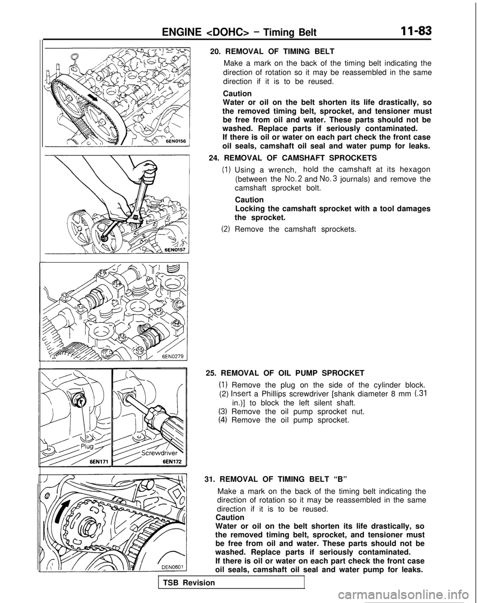
20. REMOVAL OF TIMING BELTMake a mark on the back of the timing belt indicating the
direction of rotation so it may be reassembled in the same
direction if it is to be reused.
Caution
Water or oil on the belt shorten its life drastically, so
the removed timing belt, sprocket, and tensioner must be free from oil and water. These parts should not be
washed. Replace parts if seriously contaminated. If there is oil or water on each part check the front case
oil seals, camshaft oil seal and water pump for leaks.
24. REMOVAL OF CAMSHAFT SPROCKETS
(1) Using a wrench, hold the camshaft at its hexagon
(between the No.2
and No.3
journals) and remove the
camshaft sprocket bolt.
CautionLocking the camshaft sprocket with a tool damages
the sprocket.
(2) Remove the camshaft sprockets.
25. REMOVAL OF OIL PUMP SPROCKET
(1) Remove the plug on the side of the cylinder block.
(2) Insert
a Phillips screwdriver [shank diameter 8 mm
(.31
in.)] to block the left silent shaft.
(3) Remove the oil pump sprocket nut.
(4) Remove the oil pump sprocket.
31. REMOVAL OF TIMING BELT “B” Make a mark on the back of the timing belt indicating the
direction of rotation so it may be reassembled in the same
direction if it is to be reused.
Caution
Water or oil on the belt shorten its life drastically, so
the removed timing belt, sprocket, and tensioner must be free from oil and water. These parts should not be
washed. Replace parts if seriously contaminated.
If there is oil or water on each part check the front case
oil seals, camshaft oil seal and water pump for leaks.
TSB Revision
Page 174 of 1273
13-32
FUEL SYSTEM
FUEL TANK AND FUEL LINEMlBEAAA
Symptom Probable cause Remedy
Engtne malfunctions
Bent or kinked fuel pipe or hose Repair or replace3ue to insufficient fuel
SUPPlYClogged fuel pipe or hoseClean or replace
Clogged fuel filter or in-tank fuel filter Replace
Water in fuel filter Replace the fuel filter or clean the fuel tank
and fuel line
Dirty or rusted fuel tank interior Malfunctioning fuel pump
(Clogged filter in the pump) Clean or replace
Replace
Evaporative emission Mispiping of vapor line
Correct
control system malfunc-
tions (When fuel tank Disconnect vapor line piping joint Correct
filler tube cap is re- moved, pressure releas-
Folded, bent, cracked or clogged vapor line Replace
ng noise is heard) Faulty fuel tank filler tube cap
Malfunctioning fuel tank pressure control
valve Replace
Replace
LL
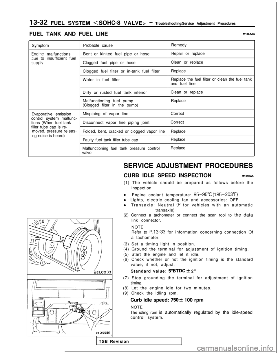
m ~~ : Paper clip-
F l!;“I /yFp- -
izd--_7-01
A0086SERVICE ADJUSTMENT PROCEDURES
CURB IDLE SPEED INSPECTION
MlBFHAFt
(1) The vehicle should be prepared as follows before the inspection.
lEngine coolant temperature: 85-95°C (185-203°F)
l Lights, electric cooling fan and accessories: OFF
l Transaxle: Neutral
(P for vehicles with an automatic
transaxle)
(2) Connect a tachometer or connect the scan tool to the data
link connector.
NOTE
Refer to
P.13-33 for information concerning connection Of
a tachometer.
(3) Set a timing light in position.
(4) Ground the terminal for adjustment of ignition timing.
(5) Start the engine and let it idle.
(6) Check whether or not the ignition timing is the standard
value; if not, adjust.
Standard value:
5”BTDC + 2”
(7) Stop grounding the terminal for adjustment of ignition timing. .
(8) Let the engine idle for two minutes.
(9) Check the idling rpm.
Curb idle speed:
7502 100 rpm
NOTE
The idling rpm is automatically regulated by the idle-speed control system.
1
TSB Revision
Page 275 of 1273

FUEL SYSTEM
FUEL TANK AND FUEL LINEMIBEAAB
Symptom
Probable cause Remedy
Engine malfunctions
due to insufficient
fuel supply Bent or kinked fuel pipe or hose
Clogged fuel pipe or hose
Clogged fuel filter or in-tank fuel filter
Water in fuel filter Repair or replace
Clean or replace
Replace
Replace the fuel filter or clean the
fuel tank and fuel line
Dirty or rusted fuel tank interior
Clean or replace
Malfunctioning fuel pump
(Clogged filter in the pump)Replace
Evaporative emission
control system
malfunctions
[When fuel tank filler
tube cap is removed,
pressure releasingnoise is heard) Mispiping of vapor line
Disconnected vapor line piping joint
Folded, bent, cracked or clogged vapor line
Faulty fuel tank filler tube cap
Malfunctioning fuel tank pressure control valve Correct
Correct
Replace
Replace
Replace
SERVICE ADJUSTMENT
PROCEDURES
CURB IDLE SPEED INSPECTIONhll3MAE
(1) The vehicle should be prepared as follows before th
e
inspection.
lEngine coolant temperature: 85-95°C (185-203°F)
l Lights, electric cooling fan and accessories: OFF
l Transaxle: Neutral (P for vehicles with an automatic
transaxle)
(2) Connect a tachometer.
NOTE
Refer to
P.13-134 for information concerning connection Of
a tachometer.
(3) Set a timing light in position.
(4) Ground the terminal for adjustment of ignition timing.
(5) Start the engine and let it idle.
(6) Check whether or not the ignition timing is the standard
value; if not, adjust.
Standard value:
5”BTDC f 2”
(7) Stop grounding the terminal for adjustment of ignition timing.
(8) Let the engine idle for two minutes.
(9) Check the idling rpm.
Curb idle speed: 700
31100 rpm
NOTE
The idling rpm is automatically regulated by the idle aircontrol system.
(lO)lf not within the standard value range, refer to the CHECK
CHART CLASSIFIED BY PROBLEM SYMPTOMS and check
the
MFI component,
TS6 Revision1
Page 386 of 1273
13-244FUEL SYSTEM
FUEL TANK AND FUEL LINE
MlBEAAh
Symptom Probable cause Remedy
Engine malfunctions Bent or kinked fuel pipe or hose Repair or replace
due to insufficient fuel supply
Clogged fuel pipe
or hose Clean or replace
Clogged fuel filter or in-tank fuel filter Replace
Water in fuel filter Replace the fuel filter or clean the fuel tank
and fuel line
Dirty or rested fuel tank interior
Malfunctioning fuel pump
(Clogged filter in the pump) Clean or replace
Replace Zvaporative
emission Mispiping of vapor line
Correct
:ontrol system malfunc-:ions (When fuel tank
Disconnect vapor line piping joint
Correct‘iller tube cap is re-noved, pressure releas-
Folded, bent, cracked or clogged vapor lineReplaceng noise is heard)
Faulty fuel tank filler tube cap
Malfunctioning fuel tank pressure control
valve Replace
Replace
TSB Revision
I
Page 553 of 1273

14-1
COOLING
ENGINE COOLANT TEMPERATURE GAUGE
UNIT, ENGINE COOLANT
TEMPERATURE SENSOR AND ENGINE
COOLANT TEMPERATURE
SWITCH.............
31
RADIATOR ....................................................... 9
RADIATOR FAN MOTOR ASSEMBLY ..........
12
SERVICE ADJUSTMENT PROCEDURES..
.....
8
Engine Coolant Concentration Test .............
8
Engine Coolant LeakCheck
........................8
Engine Coolant
Replacement .......................
8
Radiator Cap Pressure Test .........................
8
SPECIAL TOOL................................................5
SPECIFICATIONS .............................................
2
General Specifications ..................................
2
Lubricant
....................................................... 4
CONTENTS
IM14AA-
Sealant. . . . . . . . . . . . . ..__...........’ . . . . . . . . . . . . . \
. . . . . .._.........4
ServiceSpecifications . . . . .. . . . . . . . . . . . . . . . . . . . . . . . . . . . .2
Torque
Specifications. . . . . . . . . . . . . . . . . . . . . . . . . . . . . . . . . . .3
THERMOSTAT. . . . . . . . . . . . . . . . . . . . . . . . . . . . . . . . . . . . \
. . . . . . . . . . . . .13
TROUBLESHOOTING. . . . . . . . . . . . . . . . . . . . . . . . . . . . . . . . . . . . \
. .5
No rise in temperature
Overheat
WATER HOSE AND WATER PIPE
. . . . . . . . . . . . . . . . . . . . . . . . . . . . . . . . . . .26
WATER HOSE AND WATER PIPE
WATER HOSE AND WATER PIPE
. . . . . . . . . . . . . . . . . . . . .
. . . . . . . . . . . . . . . . . . . . . . . . . . . . . ..a.....23
WATER PUMP
WATER PUMP
. . . . . . . . . . . . . . . . . . . . . . . . . . . . . . .15