1989 MITSUBISHI GALANT water pump
[x] Cancel search: water pumpPage 89 of 1273
ENGINE
11-39
Crankshaft
sprocket
F,a,!,ge Crankshaft
6EN272
0180047
Crankshaft
sprocket “B”
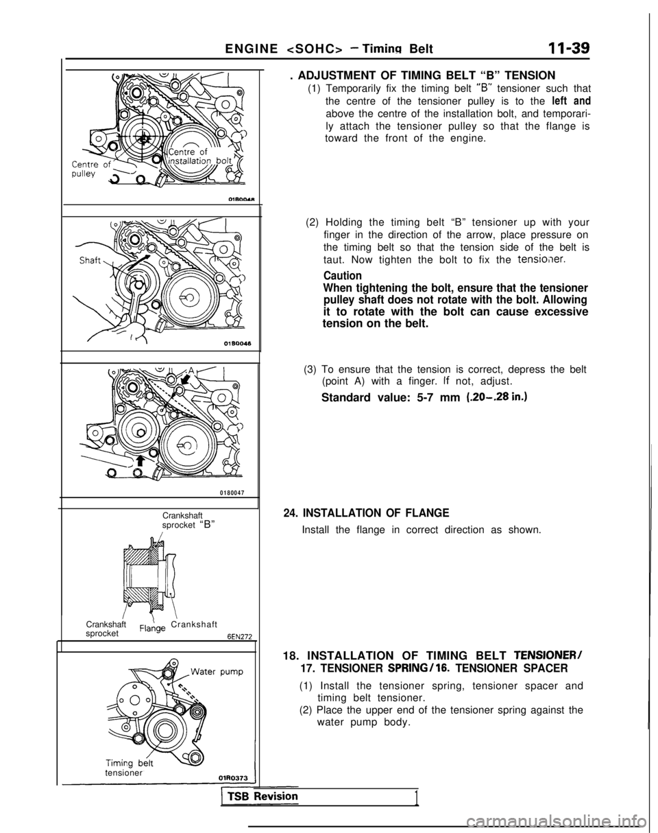
tensioner . ADJUSTMENT OF TIMING BELT “B” TENSION
(1) Temporarily fix the timing belt “B”
tensioner such that
the centre of the tensioner pulley is to the left and
above the centre of the installation bolt, and temporari-
ly attach the tensioner pulley so that the flange is
toward the front of the engine.
(2) Holding the timing belt “B” tensioner up with your finger in the direction of the arrow, place pressure on
the timing belt so that the tension side of the belt is
taut. Now tighten the bolt to fix the
tensio,ier.
Caution
When tightening the bolt, ensure that the tensioner pulley shaft does not rotate with the bolt. Allowing
it to rotate with the bolt can cause excessive
tension on the belt.
(3) To ensure that the tension is correct, depress the belt (point A) with a finger.
If not, adjust.
Standard value: 5-7 mm (.20-.28
in.)
24. INSTALLATION OF FLANGE
Install the flange in correct direction as shown.
18. INSTALLATION OF TIMING BELT
TENSIONER/
17. TENSIONER
SPRING/lG. TENSIONER SPACER
(1) Install the tensioner spring, tensioner spacer and
timing belt tensioner.
(2) Place the upper end of the tensioner spring against the water pump body.
1
Page 90 of 1273
II-40ENGINE
OlRO372
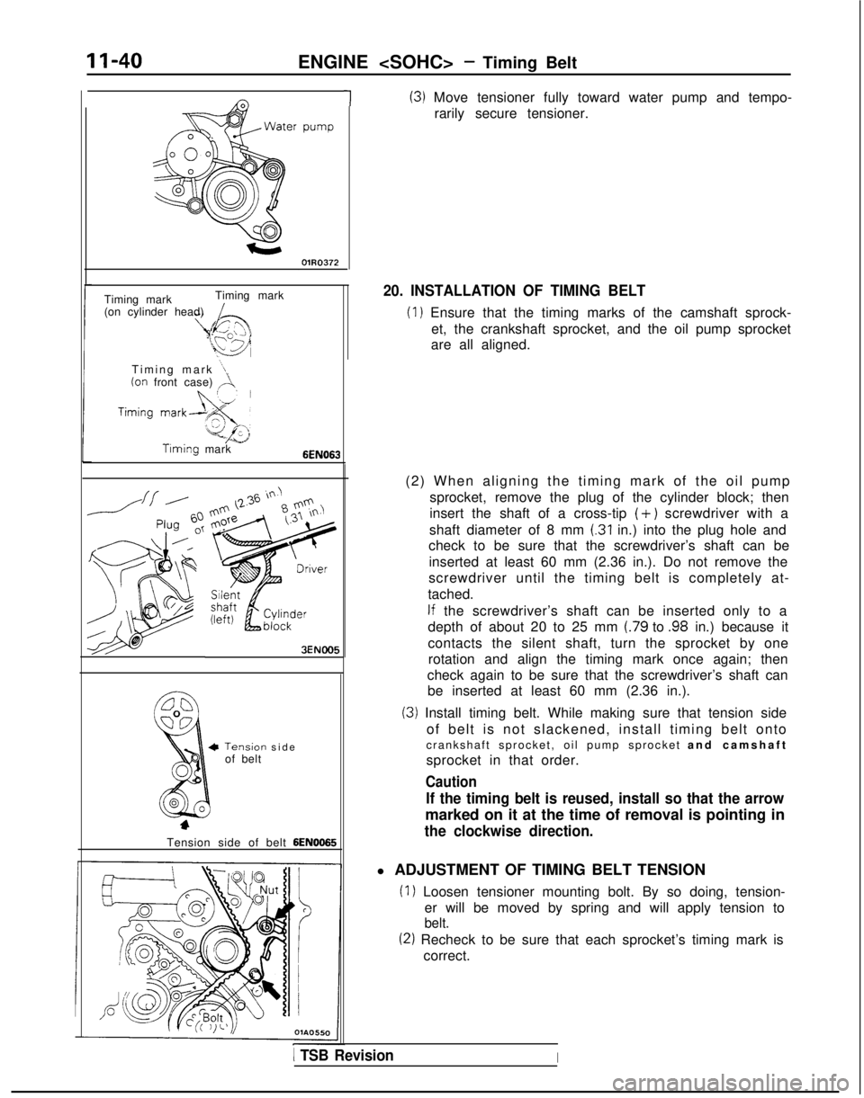
1(3) Move tensioner fully toward water pump and tempo-rarily secure tensioner.
Timing mark Timing mark
(on cylinder head)
Timing mark
“1(on front case) ,A.
Timing mark6EN063
3ENOO5
Tensiorof belt-I sid
e
Tension side of belt
6EN0065
20. INSTALLATION OF TIMING BELT
(1) Ensure that the timing marks of the camshaft sprock- et, the crankshaft sprocket, and the oil pump sprocket
are all aligned.
(2) When aligning the timing mark of the oil pump sprocket, remove the plug of the cylinder block; then
insert the shaft of a cross-tip
(+) screwdriver with a
shaft diameter of 8 mm
(.31 in.) into the plug hole and
check to be sure that the screwdriver’s shaft can be
inserted at least 60 mm (2.36 in.). Do not remove the
screwdriver until the timing belt is completely at-
tached.
If the screwdriver’s shaft can be inserted only to a
depth of about 20 to 25 mm
(.79 to .98 in.) because it
contacts the silent shaft, turn the sprocket by one rotation and align the timing mark once again; then
check again to be sure that the screwdriver’s shaft can be inserted at least 60 mm (2.36 in.).
(3) Install timing belt. While making sure that tension side
of belt is not slackened, install timing belt onto
crankshaft sprocket, oil pump sprocket and camshaf
t
sprocket in that order.
Caution
If the timing belt is reused, install so that the arrow
marked on it at the time of removal is pointing in
the clockwise direction.
l ADJUSTMENT OF TIMING BELT TENSION
(1) Loosen tensioner mounting bolt. By so doing, tension- er will be moved by spring and will apply tension to
belt.
(2) Recheck to be sure that each sprocket’s timing mark iscorrect.
1 TSB RevisionI
Page 92 of 1273
11-42
ENGINE
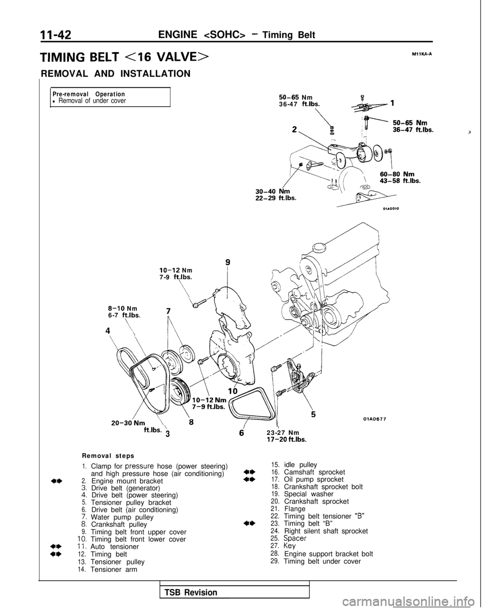
TIMING BELT
REMOVAL AND INSTALLATION
MIlKA-A
Pre-removal Operation
l Removal of under cover
8-10 Nm6-7 ftlbs.
4
’‘\ 50-65
Nm
36-47
ft.lbs.\
IO-12 Nm7-9 ftlbs.
\
\
ft.lbs.’3Q ’23-27 Nm
17-20 ft.lbs.
Removal steps
1.
2.
Clamp for
pressure
hose (power steering)
and high pressure hose (air conditioning) Engine mount bracket
Drive belt (generator) Drive belt (power steering)
Tensioner pulley bracket Drive belt (air conditioning)
Water pump pulley Crankshaft pulley
Timing belt front upper cover
Timing belt front lower cover
Auto tensioner
Timing belt OlA0677
::5.6.
i:9.10.11.
12.
13.14.Tensioner pulley
Tensioner arm
15.
::16.
17.
18.
19.
20.
21.
22.
4*23.
24.
25.
27.
28.
29.
idle pulley
Camshaft sprocket
Oil pump sprocket
Crankshaft sprocket bolt
Special washer Crankshaft sprocket
FlangeTiming belt tensioner “B”
Timing belt “B”
Right silent shaft sprocket Spacer
Kky
Engine support bracket bolt
Timing belt under cover
P
TSB Revision
Page 93 of 1273
ENGINE
+/@Service Adjustment Procedures
24?5
20-;7 Nmio
14-20 ft.lbs.\ is\ i7
Nm50-60 Nm80-94 ft.lbs.36-43 ft.lbs.
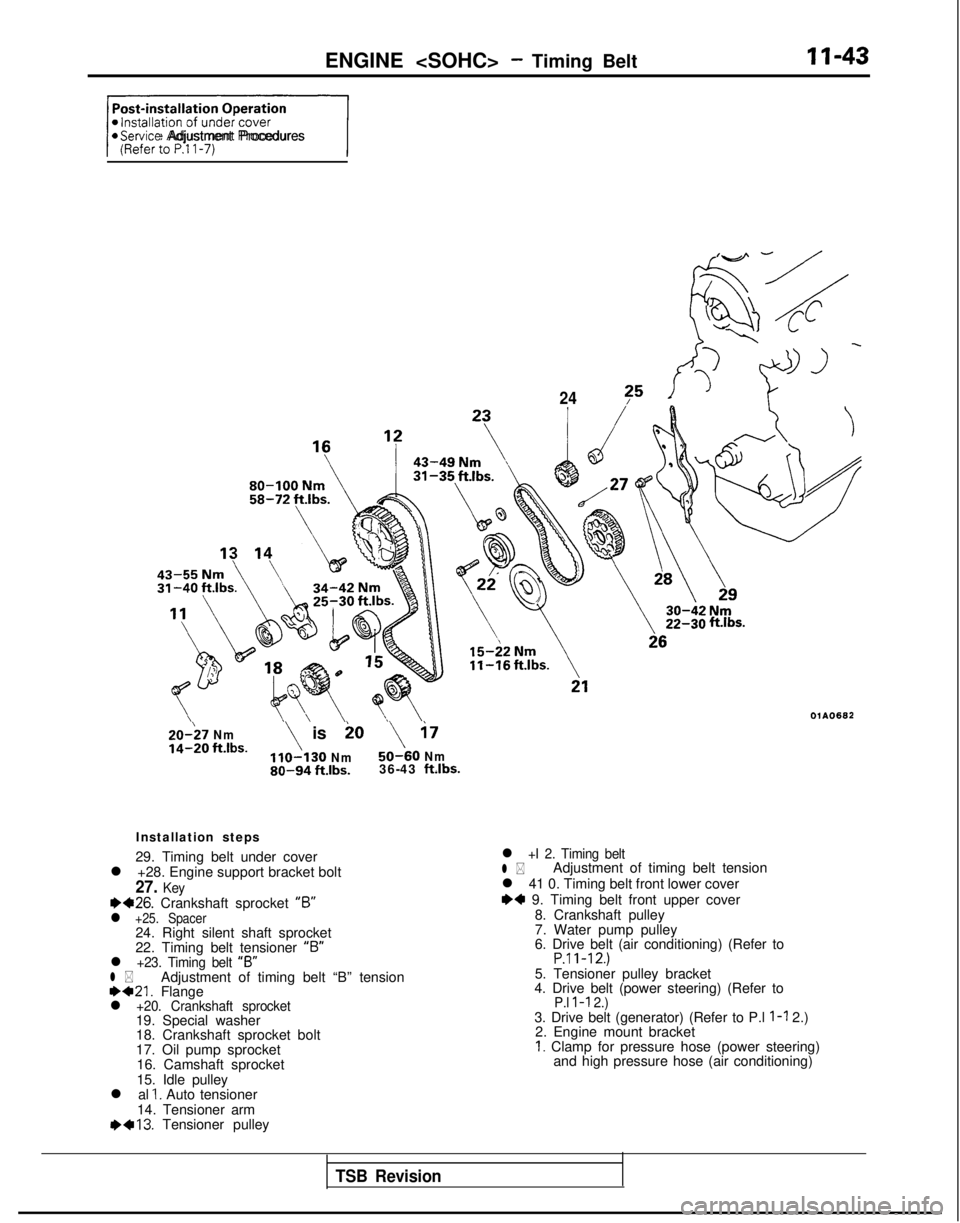
Installation steps
29. Timing belt under cover
l +28. Engine support bracket bolt
27. Keyea26. Crankshaft sprocket “6”l +25. Spacer24. Right silent shaft sprocket
22. Timing belt tensioner “B”
l +23. Timing belt
“B”l *Adjustment of timing belt “B” tension1)421. Flangel +20. Crankshaft sprocket19. Special washer
18. Crankshaft sprocket bolt
17. Oil pump sprocket
16. Camshaft sprocket
15. Idle pulley
l al
1. Auto tensioner
14. Tensioner arm 1)+13.
Tensioner pulley
ftlbs.
OlAO682
l +I 2. Timing beltl *Adjustment of timing belt tension
l 41 0. Timing belt front lower cover
I)+ 9. Timing belt front upper cover 8. Crankshaft pulley
7. Water pump pulley
6. Drive belt (air conditioning) (Refer to
P.ll-12.)5. Tensioner pulley bracket
4. Drive belt (power steering) (Refer to
P.l l-l 2.)3. Drive belt (generator) (Refer to P.l l-l 2.)
2. Engine mount bracket
I. Clamp for pressure hose (power steering) and high pressure hose (air conditioning)
TSB Revision
Page 94 of 1273
ENGINE
A Timing
mark
Timingmark
mark
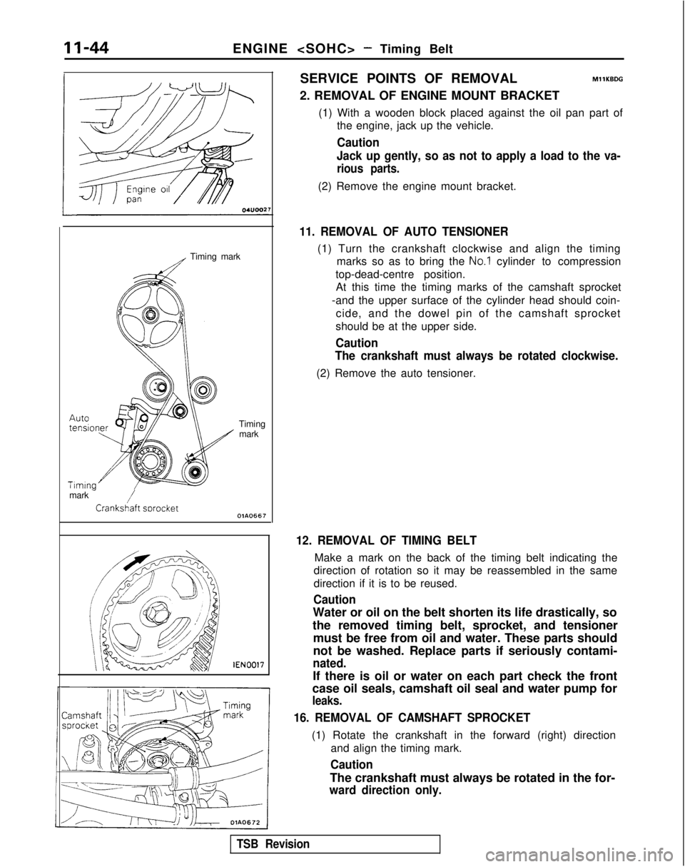
-/Crank&aft swocketOlA0667 lEN0017SERVICE POINTS OF REMOVAL
MllKBDG
2. REMOVAL OF ENGINE MOUNT BRACKET
(1) With a wooden block placed against the oil pan part ofthe engine, jack up the vehicle.
Caution
Jack up gently, so as not to apply a load to the va-
rious parts.
(2) Remove the engine mount bracket.
11. REMOVAL OF AUTO TENSIONER
(1) Turn the crankshaft clockwise and align the timing marks so as to bring the
No.1 cylinder to compression
top-dead-centre position. At this time the timing marks of the camshaft sprocket
-and the upper surface of the cylinder head should coin- cide, and the dowel pin of the camshaft sprocket
should be at the upper side.
Caution
The crankshaft must always be rotated clockwise.
(2) Remove the auto tensioner.
12. REMOVAL OF TIMING BELT
Make a mark on the back of the timing belt indicating the
direction of rotation so it may be reassembled in the same
direction if it is to be reused.
Caution
Water or oil on the belt shorten its life drastically, so
the removed timing belt, sprocket, and tensioner must be free from oil and water. These parts should
not be washed. Replace parts if seriously contami-
nated.
If there is oil or water on each part check the front
case oil seals, camshaft oil seal and water pump for
leaks.
16. REMOVAL OF CAMSHAFT SPROCKET
(1) Rotate the crankshaft in the forward (right) direction
and align the timing mark.
Caution
The crankshaft must always be rotated in the for-
ward direction only.
TSB Revision
Page 95 of 1273
ENGINE
11-45
sprocket
vlGVO001 MD998754
vlB990767-01
-
&
00B00°
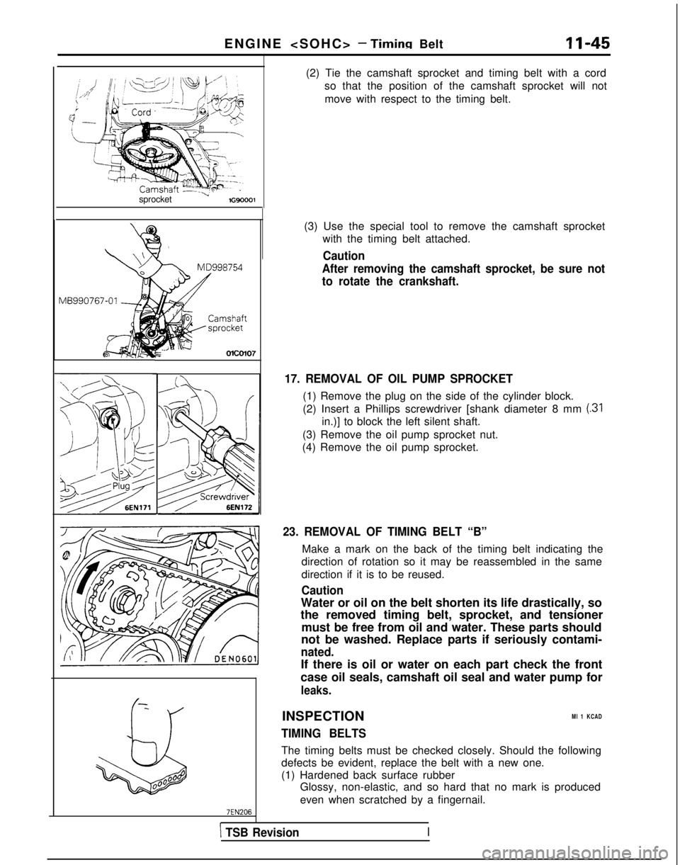
(2) Tie the camshaft sprocket and timing belt with a cord
so that the position of the camshaft sprocket will not
move with respect to the timing belt.
(3) Use the special tool to remove the camshaft sprocket with the timing belt attached.
Caution
After removing the camshaft sprocket, be sure not
to rotate the crankshaft.
17. REMOVAL OF OIL PUMP SPROCKET
(1) Remove the plug on the side of the cylinder block.
(2) Insert a Phillips screwdriver [shank diameter 8 mm
(31
in.)] to block the left silent shaft.
(3) Remove the oil pump sprocket nut.
(4) Remove the oil pump sprocket.
23. REMOVAL OF TIMING BELT “B”
Make a mark on the back of the timing belt indicating the
direction of rotation so it may be reassembled in the same
direction if it is to be reused.
Caution
Water or oil on the belt shorten its life drastically, so
the removed timing belt, sprocket, and tensioner
must be free from oil and water. These parts should
not be washed. Replace parts if seriously contami-
nated.
If there is oil or water on each part check the front
case oil seals, camshaft oil seal and water pump for
leaks.
INSPECTIONMl 1 KCAD
TIMING BELTS
The timing belts must be checked closely. Should the following
defects be evident, replace the belt with a new one.
(1) Hardened back surface rubber Glossy, non-elastic, and so hard that no mark is produced
even when scratched by a fingernail.
\ TSB RevisionI
Page 105 of 1273
ENGINE
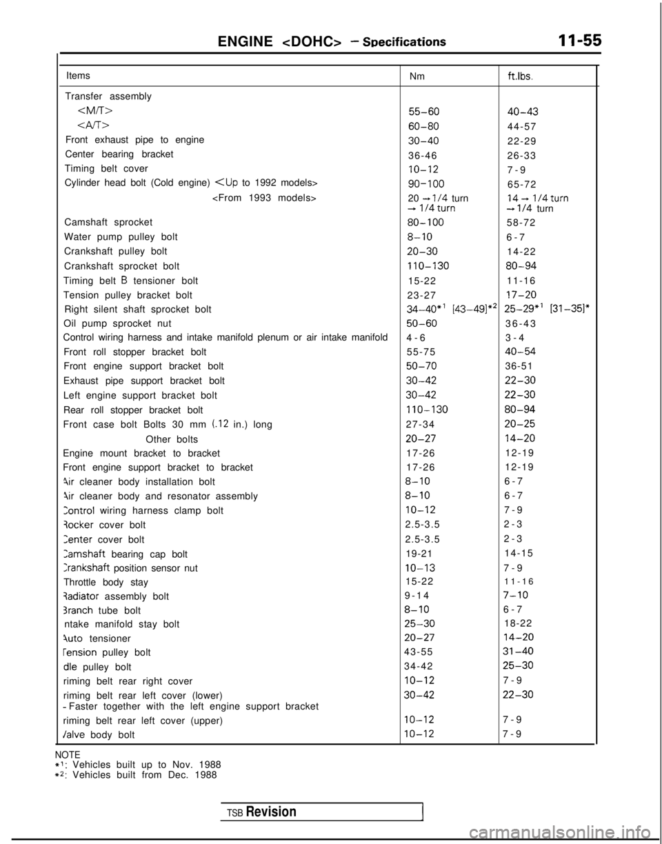
Items Nm
ft.lbs.
Transfer assembly
4f-r>60-8044-57
Front exhaust pipe to engine
30-4022-29
Center bearing bracket 36-4626-33
Timing belt cover
IO-127-
9
Cylinder head bolt (Cold engine)
-t l/4 turn14- 1/4turn+ 1!4turn--t l/4 turn
Camshaft sprocket
80-10058-72
Water pump pulley bolt
8-106-
7
Crankshaft pulley bolt
20-3014-22
Crankshaft sprocket bolt
110-13080-94
Timing belt B tensioner bolt 15-2211-16
Tension pulley bracket bolt 23-27
17-20
Right silent shaft sprocket bolt34-40*' [43-49]** 25-29*’ 131-351"
Oil pump sprocket nut50-6036-4
3
Control wiring harness and intake manifold plenum or air intake manifold\
4-63-4
Front roll stopper bracket bolt 55-75
40-54
Front engine support bracket bolt50-7036-51
Exhaust pipe support bracket bolt
30-4222-30
Left engine support bracket bolt30-4222-30
Rear roll stopper bracket bolt110-13080-94
Front case bolt Bolts 30 mm (.I2 in.) long 27-3420-25
Other bolts20-2714-20
Engine mount bracket to bracket 17-2612-19
Front engine support bracket to bracket 17-2612-19
%r cleaner body installation bolt8-106-
7
qir cleaner body and resonator assembly8-106-
7
Control wiring harness clamp boltIO-127-
9
3ocker
cover bolt 2.5-3.5
2-3Zenter
cover bolt 2.5-3.52-3Camshaft
bearing cap bolt 19-2114-15
Crankshaft position sensor nutIO-137-
9
Throttle body stay 15-22
11-163adiator
assembly bolt 9-14
7-10
3ranch tube bolt8-106-
7
ntake manifold stay bolt
25-3018-22
quto tensioner20-2714-20 rension
pulley bolt 43-55
31-40dle
pulley bolt 34-42
25-30
riming belt rear right cover10-127-
9
riming belt rear left cover (lower)
30-4222-30 - Faster together with the left engine support bracket
riming belt rear left cover (upper)
IO-127-
9
Jalve body boltIO-127-
9
NOTE*I: Vehicles built up to Nov. 1988**: Vehicles built from Dec. 1988
TSB Revision1
Page 112 of 1273
II-62ENGINE
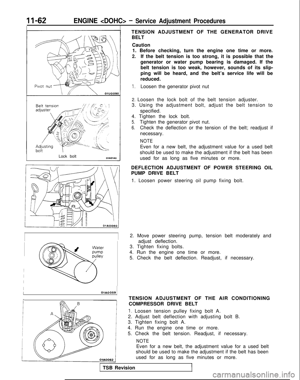
Lock boltTENSION ADJUSTMENT OF THE GENERATOR DRIVE
BELT
Caution
1. Before checking, turn the engine one time or more.
2.If the belt tension is too strong, it is possible that the
generator or water pump bearing is damaged. If the belt tension is too weak, however, sounds of its slip-
ping will be heard, and the belt’s service life will be
reduced.
1.Loosen the generator pivot nut
2. Loosen the lock bolt of the belt tension adjuster.
3. Using the adjustment bolt, adjust the belt tension to
specified.
4. Tighten the lock bolt.
5.Tighten the generator pivot nut.
6.Check the deflection or the tension of the belt; readjust if
necessary.
NOTE
Even for a new belt, the adjustment value for a used belt
should be used to make the adjustment if the belt has been used for as long as five minutes or more.
DEFLECTION ADJUSTMENT OF POWER STEERING OIL
PUMP DRIVE BELT 1. Loosen power steering oil pump fixing bolt.
2. Move power steering pump, tension belt moderately and adjust deflection.
3. Tighten fixing bolts.
4. Run the engine one time or more. 5. Check the belt deflection. Readjust, if necessary.
IIOlA0059
r
TSB Revision TENSION ADJUSTMENT OF THE AIR CONDITIONING
COMPRESSOR DRIVE BELT
1. Loosen tension pulley fixing bolt A.
2. Adjust belt deflection with adjusting bolt B.
3. Tighten fixing bolt A.
4. Run the engine one time or more. 5. Check the belt tension. Readjust, if necessary.
NOTE
Even for a new belt, the adjustment value for a used belt
should be used to make the adjustment if the belt has been
used for as long as five minutes or more.