Page 67 of 1273
ENGINE -- Engine Assembly
ENGINE ASSEMBLY
REMOVAL AND INSTALLATION
II-17
Pre-removal Operation@Eliminating Fuel Pressure in Fuel Line (Refer to GROUP 13-Service Adjustment Proce-
dures.)
l Removal of the Hood
(Refer to GROUP
42-Hood.)l Draining of the Engine Coolant
(Refer to GROUP 00-Maintenance Service)
l Removal of the Transaxle (Refer to GROUP
22,23-Transaxle.)l Removal of the Radiator(Refer to GROUP 14-Radiator.)
Fuel rail
603AOO70
Engine oil
Post-installation Operationl Installation of the Radiator (Refer to GROUP 14-Radiator.)l Installation of the Transaxle(Refer to GROUP 22, 23-Transaxle.)l Refilling of the Engine Coolant
(Refer to GROUP 00-Maintenance Service.)
l Installation of the Hood (Refer to GROUP
42-Hood.)
4-6 Nm3-F ft.lbs.
I6m
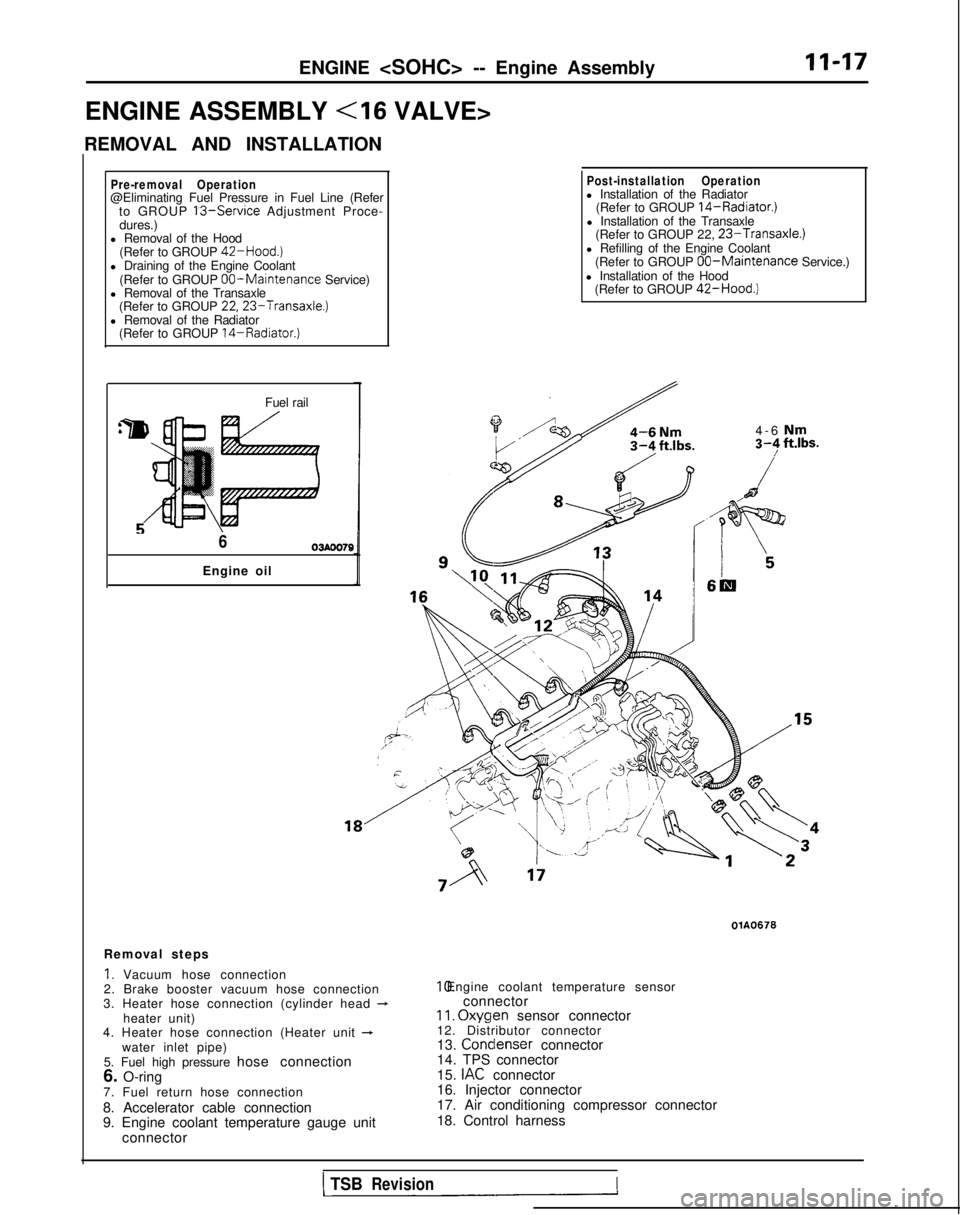
Removal steps
1. Vacuum hose connection
2. Brake booster vacuum hose connection
3. Heater hose connection (cylinder head
-heater unit)
4. Heater hose connection (Heater unit +water inlet pipe)
5. Fuel high pressure hose connection
6. O-ring
7. Fuel return hose connection
8. Accelerator cable connection
9. Engine coolant temperature gauge unit connector
OlA0676 10. Engine coolant temperature sensor
connector
II. Oxyqen
sensor connector
12. Distributor connector
13. Condenser
connector
14. TPS connector
15.
IAC connector
16. Injector connector
17. Air conditioning compressor connector
18. Control harness
1 TSBRevisionI
Page 68 of 1273
11-18
ENGINE - Engine Assembly
35-45 Nm 35-45 Nm
25-33
ft.lbs.I
35-45 Nm/ 25-33 ft.lbs.
23-27,‘17-20
Lf+gPf--
2001A0671
36-47 ft.lbs. 40-5o’Nm
29-36
ft.lbs.
Removal steps
19. Connection for generator
20. Connection for oil pressure switch+e l a21 Power steering oil pump (Refer toP.ll-16.)+e .422. Air conditioning compressor (Refer to
P.l 1-16.)23. Self-locking nuts
24. Gasket -
l *
25. Clamp of pressure hose (Power steering)
and high pressure hose (Air conditioning)
26. Engine mount bracket (Refer to P.l l-l 6.)
27. Self locking nut
+* l C28. Engine assembly (Refer to P.l I-16.) 60-80
Nm43-58 ft.lbs.
OlAO670
1 TSB Revision
Page 77 of 1273
ENGINE - Cylinder Head Gasket11-27
\
r
MatingC
-I
1
J-1.‘T
:-c’ 000510020
SERVICE POINTS OF REMOVALMllJBAl
3. DISCONNECTION OF FUEL HIGH PRESSURE HOSE
Caution
Cover the hose connection with rags to prevent splash
of fuel that could be caused by some residual pressure
in the fuel pipe line.
For information concerning the bleeding of the residual
pressure, refer to GROUP
13-On-Vehicle Inspection of
MFI
Components.
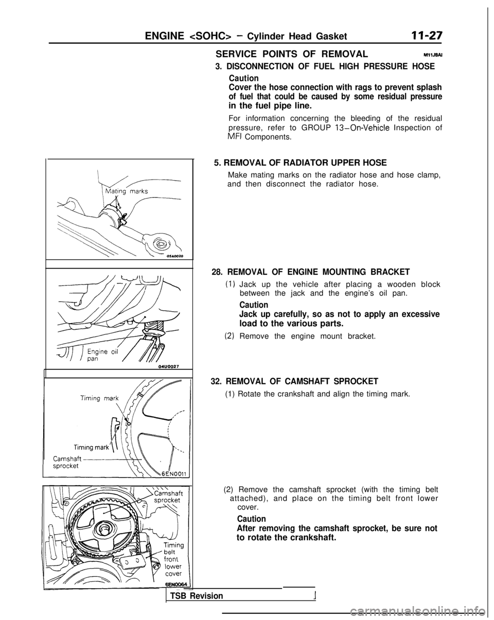
5. REMOVAL OF RADIATOR UPPER HOSE Make mating marks on the radiator hose and hose clamp,
and then disconnect the radiator hose.
28. REMOVAL OF ENGINE MOUNTING BRACKET
Jack up the vehicle after placing a wooden block between the jack and the engine’s oil pan.
Caution
Jack up carefully, so as not to apply an excessive
load to the various parts.
Remove the engine mount bracket.
32. REMOVAL OF CAMSHAFT SPROCKET
(1) Rotate the crankshaft and align the timing mark.
(2) Remove the camshaft sprocket (with the timing belt attached), and place on the timing belt front lower cover.
Caution
After removing the camshaft sprocket, be sure not
to rotate the crankshaft.
TSB Revision
Page 79 of 1273
ENGINE - Cylinder Head GasketII-29
Front of engine I)Intake side
6EN094
Exhaust side
OlR0391
Fuel rail
pr&surehose\0-nng
TSB Revision
(2) Using the special tool, tighten the bolts in the order
shown in two or three steps.
5. INSTALLATION OF RADIATOR UPPER HOSE
Align the mating marks (of the radiator hose and hoseclamp), and then, while applying force in the direction of
the arrow in the illustration, seat the hose clamp to the
trace marks (on the hose) remaining from the prior connection.
Caution Be sure to install the hose clamp at the trace marks (on
the hose) remaining from the prior connection.
3. CONNECTION OF FUEL HIGH PRESSURE HOSE
When connecting the high-pressure fuel hose to the fuel rail, apply a coating of engine oil to the hose union, and in-
sert so that the O-ring is not damaged.
Page 80 of 1273
II-30ENGINE - Cylinder Head Gasket
CYLINDER HEAD GASKET
REMOVAL AND INSTALLATION
Ml IJA-C
Pre-removal Operationl Releasing of Fuel Line Pressure(Refer to GROUP 13-Service Adjust-ment Procedures.)l Draining of the Engine Coolant(Refer to GROUP 14-Service Adjust-
ment Procedures.)
l Draining of the Engine Oil
il4-6 Nm
Post-installation Operationl Supplying of the Engine Coolant(Refer to GROUP 14-Service Adjust-ment Procedures.)l Supplying of the Engine Oill Accelerator Cable Adjustment(Refer to GROUP 13-Service Adjust-ment Procedures.)
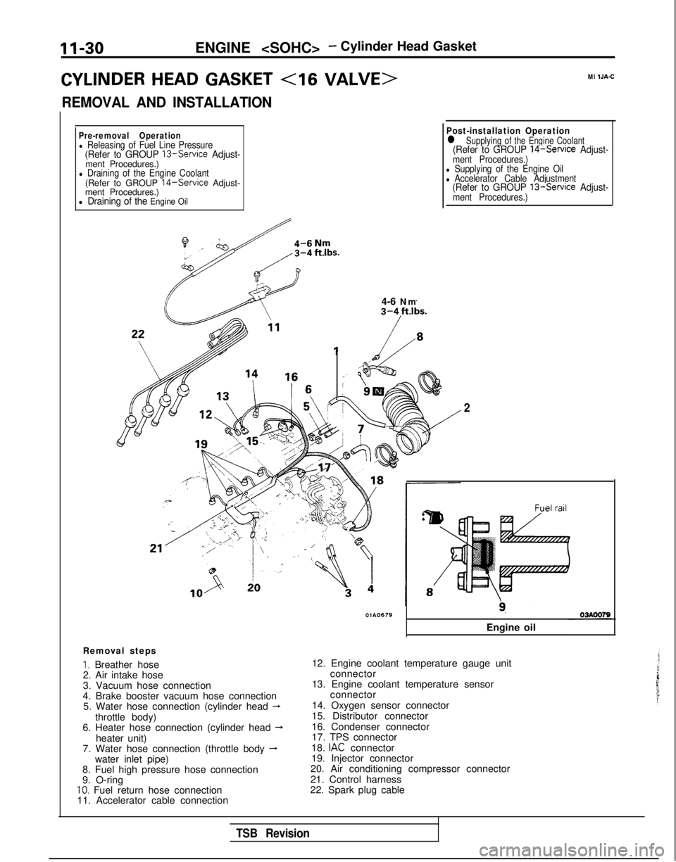
Removal steps
I. Breather hose
2. Air intake hose
3. Vacuum hose connection
4. Brake booster vacuum hose connection 5. Water hose connection (cylinder head
-throttle body)
6. Heater hose connection (cylinder head --Lheater unit)
7. Water hose connection (throttle body -water inlet pipe)
8. Fuel high pressure hose connection
9. O-ring
10. Fuel return hose connection
11. Accelerator cable connection
2
9.
Engine oil
12. Engine coolant temperature gauge unit connector
13. Engine coolant temperature sensor connector
14. Oxygen sensor connector
15. Distributor connector
16. Condenser connector
17. TPS connector
18.
IAC connector
19. Injector connector
20. Air conditioning compressor connector
21. Control harness
22. Spark plug cable
TSB Revision
Page 84 of 1273
11-34
ENGINE - Timina Belt
TIMING BELT (8 VALVE>MIlKA-A
REMOVAL AND INSTALLATION
Pre-removal OperationaRemoval of under cover 50-65
Nm
36-47 ftlbs.
\ 22-29
ft.lbs.
ft.lbs.
IO-12 Nm
7-9 ft.lbs. 10
m\../.8-10 N6-7 ft.lbs.\
20-30 N,/ v \R \OlAO43414-22 ft.lbs. \I3
10-12’
Nm7-S ftlbs.
6
23-27 Nm 17-20
ft.lbs.
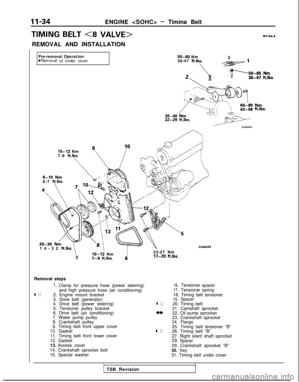
Removal steps
1. Clamp for pressure hose (power steering)
and high pressure hose (air conditioning)
l *2. Engine mount bracket
3. Drive belt (generator)
4. Drive belt (power steering)
5. Tensioner pulley bracket
6. Drive belt (air conditioning)
7. Water pump pulley
8. Crankshaft pulley
9. Timing belt front upper cover
10. Gasket
11. Timing belt front lower cover
12. Gasket
13. Access cover
14. Crankshaft sprocket bolt
15. Special washer
16.Tensioner spacer17.Tensioner spring
18. Timing belt tensioner
19.Spacerl *20. Timing belt21.Camshaft sprocket*‘I)22. Oil pump sprocket23.24.Crankshaft sprocketFlange25. Timing belt tensioner “B”l *26. Timing belt “B”
27. Right silent shaft sprocket
28.Spacer29. Crankshaft sprocket “B”30.Key31. Timing belt under cover
TSB Revision
Page 85 of 1273
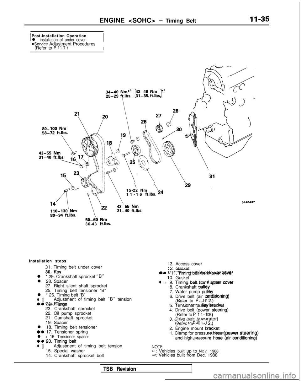
ENGINE - Timing BeltII-35
IPost-installation Operationl installation of under coverIaService Adjustment Procedures
(Refer to P.ll-7.)I 50-60
Nm36-43 ftlbs.
31
\\15-22 Nm
11-16 ft.lbs. 24
01 A0437
30. KevIL. -I"..--+A ‘IIT:m;nn halt fmnf lower cover
Installation steps
31. Timing belt under cover
30. Key
l * 29. Crankshaft sprocket
“B”l 28. Spacer 27. Right silent shaft sprocket
25. Timing belt tensioner “B”
l * 26. Timing belt “B”
l 4Adjustment of timing belt “B” tensionl * 24. Flange23. Crankshaft sprocket
22. Oil pump sprocket
21. Camshaft sprocket
19. Spacer
l 18. Timing belt tensioner
~~ 17. Tensioner springl + 16. Tensioner spacer++ 20. Timing beltl 4Adjustment of timing belt tension
15. Special washer 14. Crankshaft sprocket bolt
tic 24. Flanae
, UtiIL , , WI ,t upper cover!hcaft n, dlqy
lb. :;d)rtroning)
\..“.w.
.-c
T-mrinnar r
nliny bracket
er steering)1 2.)
19. Spacer
++ 20. Timing belt13. Access cover
12. Gasket
l +
11. Timing belt front lower cover10. Gasketl +9. Timing belt front upper cover 8. Crankshaft pulley
7. Water pump pulley
6. Drive belt (air conditioning) (Refer to P.l l-l 2.)
5. Tensioner pulley bracket
4. Drive belt (power steering)
(Refer to
P. 1 l-l 2.)
3. Drive belt (generator) (Refer to P.l l-l 2.)
2. Engine mount bracket 1. Clamp for pressure hose (power steering)
and high pressure hose (air conditioning)
NOTE*I: Vehicles built up to N O
V. 1988
+2: Vehicles built from Dec. 1988 lrator)
U. Vll”” ““SC \y”v’ulRpfcw tn P 1 l-l
2.)
racket
NOT=
ure hose (power steering)
s-4, I” I “..J’I p.. .#““.are hose (air conditioning)
TSB Revision
TSB Revision
Page 91 of 1273
ENGINE - Timina Belt11-41
I
I
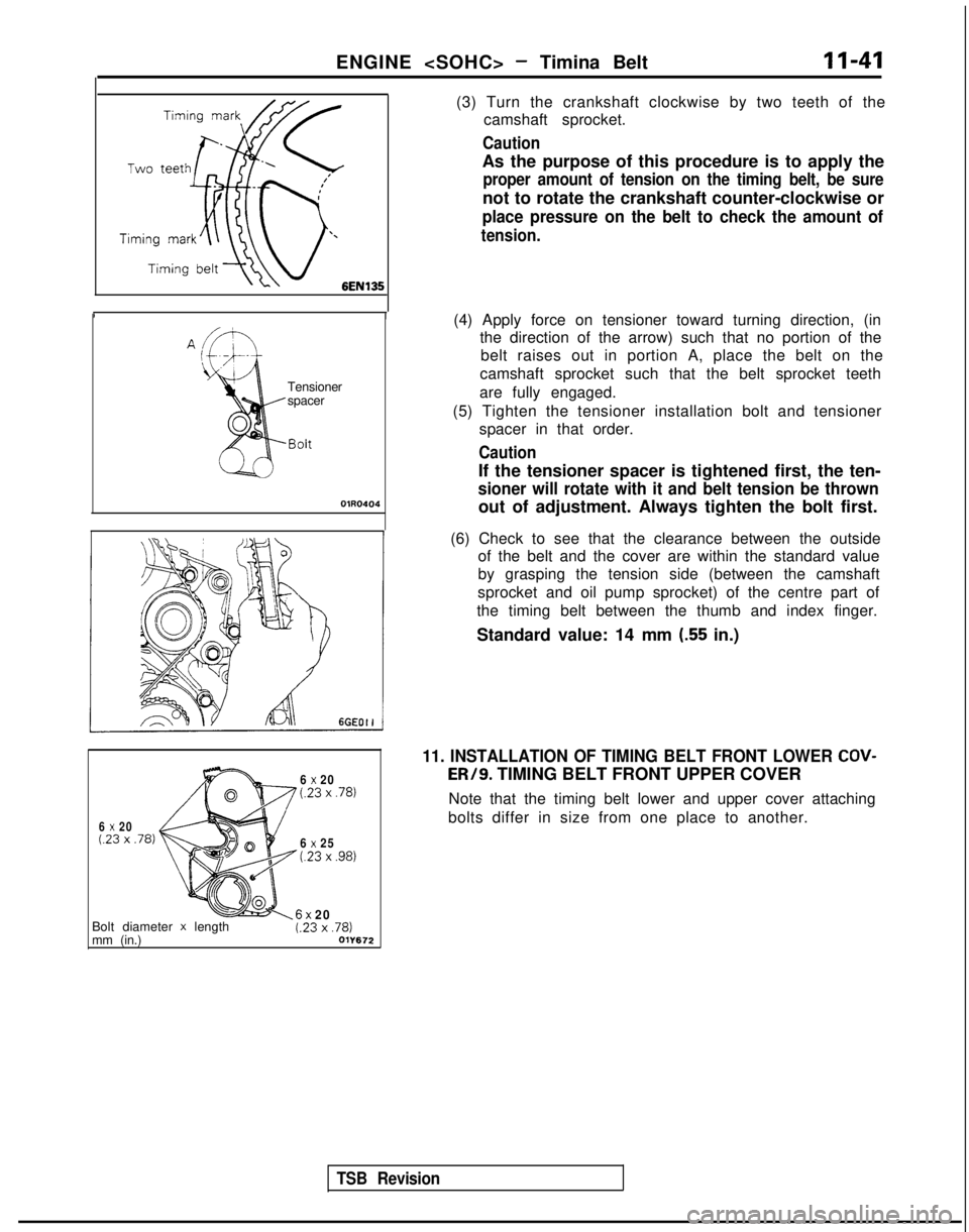
(3) Turn the crankshaft clockwise by two teeth of the
camshaft sprocket.
Caution
As the purpose of this procedure is to apply the
proper amount of tension on the timing belt, be sure
not to rotate the crankshaft counter-clockwise or
place pressure on the belt to check the amount of
tension.
Tensioner
spacer
OlR0404
(4) Apply force on tensioner toward turning direction, (inthe direction of the arrow) such that no portion of the
belt raises out in portion A, place the belt on the
camshaft sprocket such that the belt sprocket teeth
are fully engaged.
(5) Tighten the tensioner installation bolt and tensioner spacer in that order.
Caution
If the tensioner spacer is tightened first, the ten-
sioner will rotate with it and belt tension be thrown
out of adjustment. Always tighten the bolt first.
TSB Revision
(6) Check to see that the clearance between the outside of the belt and the cover are within the standard value
by grasping the tension side (between the camshaft
sprocket and oil pump sprocket) of the centre part of
the timing belt between the thumb and index finger.
Standard value: 14 mm
(.55 in.)
6 x 20(23 x .78)
6 x 20(23 x .78)
6 x 25t.23 x ,981
11. INSTALLATION OF TIMING BELT FRONT LOWER COV- ER/9.
TIMING BELT FRONT UPPER COVER
Note that the timing belt lower and upper cover attaching
bolts differ in size from one place to another.
Bolt diameter
x length
mm (in.)6x 20t.23 x ,781011672