Page 257 of 1273
FUEL SYSTEM
VALVE> -Fuel Line and Vapor Line/Fuel Filter 13-115
Higt
fuel
&ring Oi’
FUEL FILTER
REMOVAL AND INSTALLATION
~zgz&i&r” 1@Release of Residual Pressure from High
2. INSTALLATION OF HIGH PRESSURE FUEL HOSE
Apply engine oil to the hose union.Insert the hose, being careful not to damage the O-ring, and
tighten securely.
Caution Because there is high pressure applied between the
fuel pump and the injection mixer, be especially sure
that there is no fuel leakage in this area.
25-35 N
m
18-25
ft.lbs.
Post-installation Operation@Measurement of Fuel Pressure
Fuel filter removal steps
1. Eye bolt (Refer to P.13-114.)2. O-ring3. Connection for high pressure fuel hose
4. O-ring
5. Connection for fuel main pipe
6. Mounting bolt
7. Fuel filter (Refer to P.13-114.)
TSB Revision 03AO231
Page 261 of 1273
Page 264 of 1273
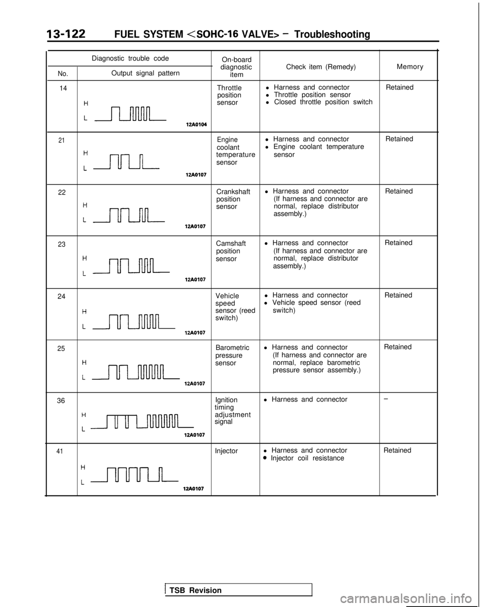
13-122FUEL SYSTEM - Troubleshooting
Diagnostic trouble codeOn-board
diagnostic Check item (Remedy) Memory
No.Output signal pattern
item
14Throttlel Harness and connector
Retained
position l Throttle position sensor
:n
sensor l Closed throttle position switch
12Ao104
21Enginel Harness and connector
Retained
coolant l Engine coolant temperature
Cnn
temperature
sensor
sensor
lzAO107
22Crankshaft l Harness and connector
Retained
position (If harness and connector are
:nn
sensor normal, replace distributor
assembly.)
lzAOlO7
23Camshaft l Harness and connector
Retained
position (If harness and connector are
:-
sensor normal, replace distributor
assembly.)
12Ao107
24 Vehiclel Harness and connector
Retained
speed l Vehicle speed sensor (reed
Hsensor (reed
switch)
switch)
LULl-uulnlzAO107
25
H
Barometric
pressure l Harness and connector
(If harness and connector are
LULMlvul
sensor normal, replace barometric
pressure sensor assembly.)
VA0107
Retained
36 Ignition
l Harness and connector
-
timingH
Lu u LnllMnn
adjustment
signal
12Ao107
41Injector l Harness and connector0 Injector coil resistance Retained
12Ao107
1 TSB Revision
Page 269 of 1273
Page 281 of 1273
FUEL SYSTEM - ?::;:r%t~pection Of MF’13439
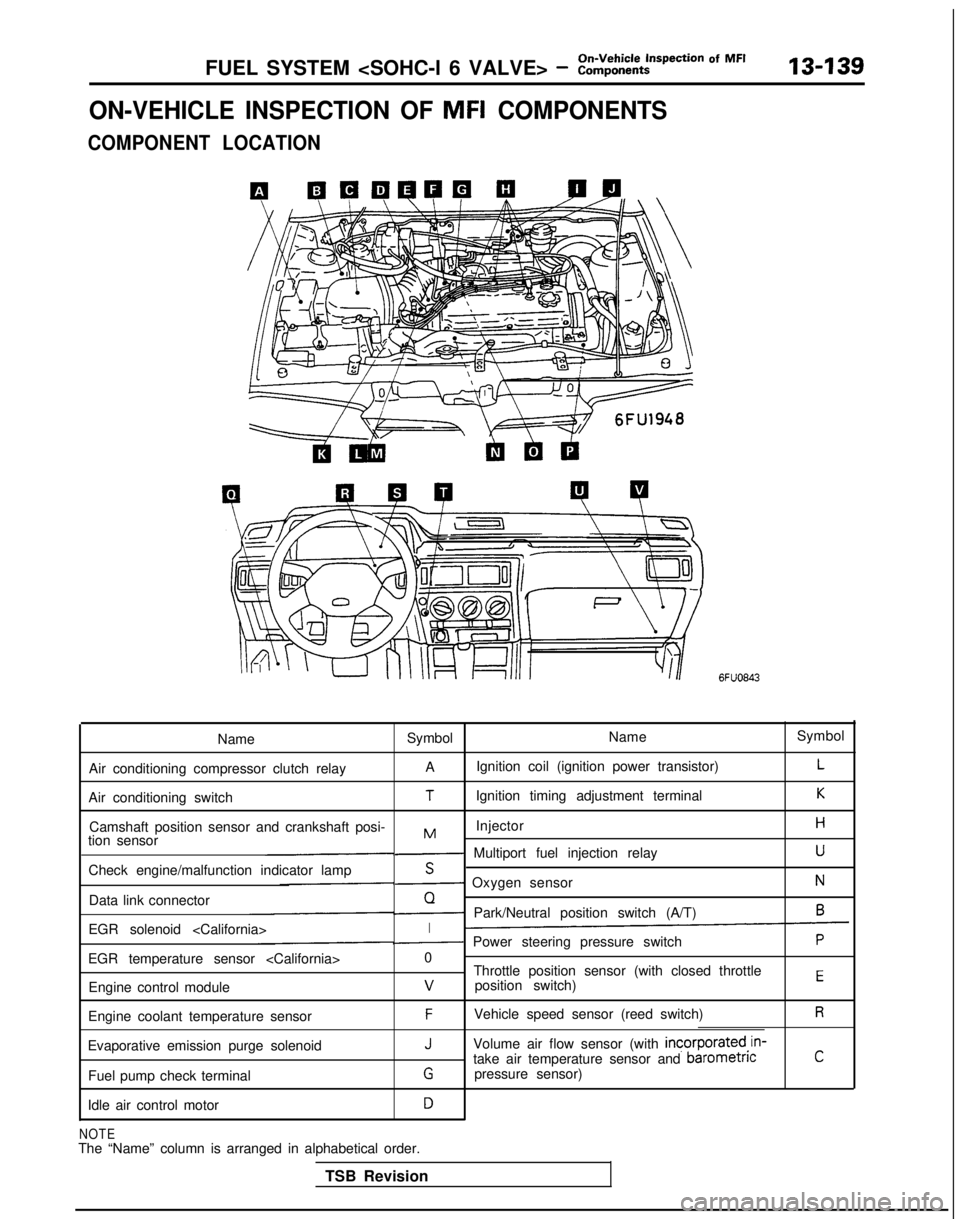
ON-VEHICLE INSPECTION OF MFI COMPONENTS
COMPONENT LOCATION
6FUO843
Name Symbol NameSymbol
Air conditioning compressor clutch relay A
Ignition coil (ignition power transistor)
L
Air conditioning switchTIgnition timing adjustment terminalK
Camshaft position sensor and crankshaft posi- InjectorHMtion sensor- Multiport fuel injection relayU
Check engine/malfunction indicator lampS- Oxygen sensorN
Data link connectorQ- Park/Neutral position switch (A/T)6
EGR solenoid I- Power steering pressure switchP
EGR temperature sensor 0
Throttle position sensor (with closed throttle
position switch)
EEngine control modulev
Engine coolant temperature sensorFVehicle speed sensor (reed switch)R
Evaporative emission purge solenoidJVolume air flow sensor (with incorporated,in-
take air temperature sensor and barometncC
Fuel pump check terminalGpressure sensor)
Idle air control motor
D
NOTEThe “Name” column is arranged in alphabetical order. TSB Revision
Page 326 of 1273
13-184
On-Vehicle Inspection of MFI
FUEL SYSTEM (SOHC-16 VALVE> - Components
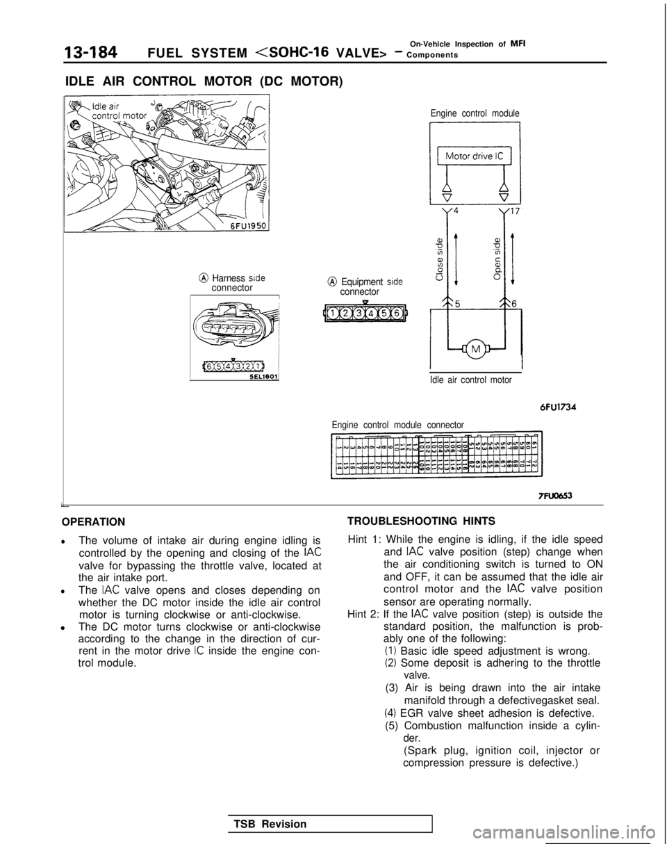
IDLE AIR CONTROL MOTOR (DC MOTOR)
@ Harness sideconnectorI L
[@Ex@ziJ 1
5ELWOlJ
j
e;
j 55ww3 )A’,’/
@ Equipment sideconnector
Engine control module
Idle air control motor
6FU1734
Engine control module connector
7FUCJG3
OPERATION
lThe volume of intake air during engine idling is controlled by the opening and closing of the
IAC
valve for bypassing the throttle valve, located at
the air intake port.
lThe IAC valve opens and closes depending on
whether the DC motor inside the idle air control motor is turning clockwise or anti-clockwise.
l The DC motor turns clockwise or anti-clockwise
according to the change in the direction of cur-
rent in the motor drive
IC inside the engine con-
trol module. TROUBLESHOOTING HINTS
Hint 1: While the engine is idling, if the idle speed and
IAC valve position (step) change when
the air conditioning switch is turned to ON
and OFF, it can be assumed that the idle air
control motor and the
IAC valve position
sensor are operating normally.
Hint 2: If the
IAC valve position (step) is outside the
standard position, the malfunction is prob-
ably one of the following: (I)
Basic idle speed adjustment is wrong.
(2) Some deposit is adhering to the throttle
valve.
(3) Air is being drawn into the air intake
manifold through a defectivegasket seal.
(4) EGR valve sheet adhesion is defective.
(5) Combustion malfunction inside a cylin-
der.
(Spark plug, ignition coil, injector or
compression pressure is defective.)
TSB Revision
Page 338 of 1273
13-196FUEL SYSTEM - General Information
FUEL SYSTEM
GENERAL INFORMATION
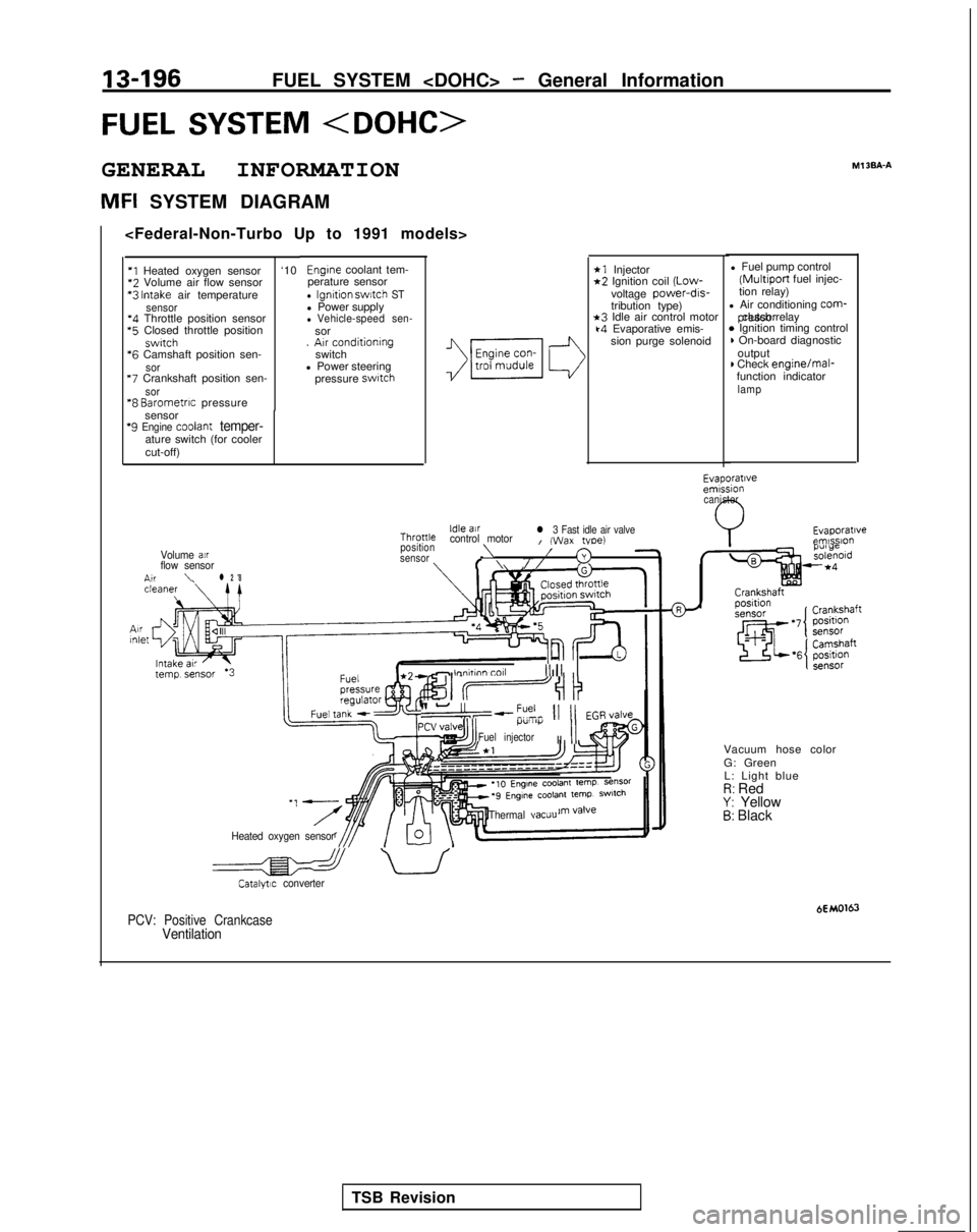
MFI SYSTEM DIAGRAMMl
3BA-A
*1 Injector*2 Ignition coil
(Low-
voltage power-drs-
tribution type)
*3 Idle air control motork4 Evaporative emis-
sion purge solenoid l Fuel pump control (Multiport
fuel injec-
tion relay)
l Air conditioning
corm- pressor clutch relay
* Ignition timing control) On-board diagnostic
output
) Check engine/mal-
function indicator
lamp
Engine coolant tem-
perature sensor
l Ignition swatch STl Power supplyl Vehicle-speed sen-sor
. Arr conditioning
switch
l Power steering
pressure
swatch
‘I Heated oxygen sensor ‘10*2
Volume air flow sensor *3
Intake air temperaturesensor‘4 Throttle position sensor *5
Closed throttle position
swrtch *6
Camshaft position sen-
sor “7
Crankshaft position sen-
sor“8 Barometrrc pressure
sensor
‘9 Engine coolant temper-ature switch (for cooler
cut-off)
Evaporatrveemrssion canister
Evaporatrveemlsslo”Idle airThronlecontrol motorl 3 Fast idle air valveI (Wax tvoe)position\Volume air/sensor3flow sensorf \//n,r\l 2 '8
- lnnhnn toll III1 II
II-“,--?% 11 11 EGR,/alveI.l”lll)i
Fuel injectorII
II
Vacuum hose color
G: Green
L: Light blue
I?: RedY: Yellow5: Black
Heated oxygen sensor Thermal
vacuu
a uCatalytrc converter
HMO163PCV: Positive CrankcaseVentilation
TSB Revision
Page 339 of 1273
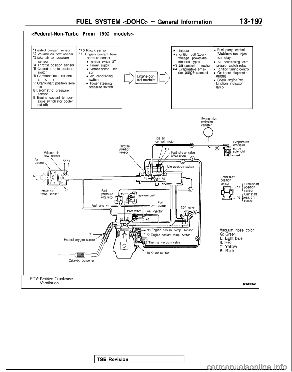
‘1 Heated oxygen sensor‘2 Volume air flow sensor
“3 intake air temperature
sensor‘4 Throttle position sensor‘5 Closed throttle position
switch
‘6 Camshaft Dosltion sen-
so
r
*7 Crankshaft position sen-sor‘8
Barometnc
pressure
sensor
‘9 Engine coolant temper-
ature switch (for cooler
cut-off)
‘I 0 Knock sensor ‘11
Engien coolant tem-
perature sensor
l Ignition switch STl Power supplyl Vehicle-speed sen-
sor
l Air conditioningswitchl Power steeringpressure switch
Volume airflow sensor \
Idle air
FUEL SYSTEM - General Information13-197
* 1 Injector*2 Ignition coil (Low-
voltage power-dis-
tribution type)
*3 Idle air control motel*4 Evaporative emis-sion purge solenoid
l Fuel pump control (Multiport
fuel injec-
tion relay)
l Air conditioning com-pressor clutch relay
l Ignition timing control
l On-board diagnosticoutputl Check engine/mal-
function indicator
lamp
Evaporativeemissioncanister
Q
ThrottlepOSltlOnSt?“SW
\
control motor
r
Fast Idle air valveWax tape)
TSB Revision
e , lylllll”rl
COll
Fuel- wmpEGR valve
'1 A
Heated oxygen sensor /$$y/.\‘“I
w ‘11 Englen coolant temp. sensorF ‘9 Engine coolant temp. switch
Thermal vacuum valve
Crankshaft
position
sensor
‘7 positlon ICrankshaft
sensor
I
Camshaft‘6 positionsensor
Vacuum hose color G: Green
L: Light blueR: RedY: YellowB: Black
Catalytic convener
PCV: Posmve CrankcaseVentllatlon6EMO362