1989 MITSUBISHI GALANT oil pressure
[x] Cancel search: oil pressurePage 123 of 1273
ENGINE
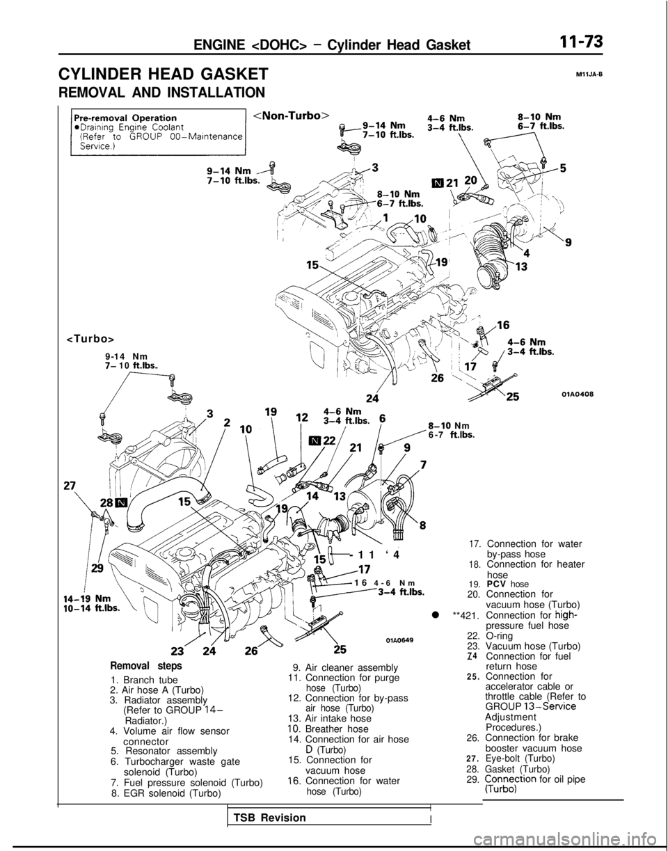
CYLINDER HEAD GASKET
MllJA-9
REMOVAL AND INSTALLATION
7- 10 ft.lbs.
OlA0408
8-10 Nm
6-7 ft.lbs.
-11 ‘
4
A17
-16
4-6 N
m
---3-4
ftlbs.
OlA0649
17.
18.
19.20.
l **421.
22.
23.
74Removal steps
1. Branch tube
2. Air hose A (Turbo)
3. Radiator assembly (Refer to GROUP
14-Radiator.)
4. Volume air flow sensor
connector
5. Resonator assembly
6. Turbocharger waste gate solenoid (Turbo)
7. Fuel pressure solenoid (Turbo) 8. EGR solenoid (Turbo)
-
9. Air cleaner assembly
11. Connection for purge25.
hose (Turbo)12. Connection for by-passair hose (Turbo)13. Air intake hose10. Breather hose
14. Connection for air hose26.
D (Turbo)15. Connection for27.
vacuum hose28.
16. Connection for water29.
hose (Turbo)
I
Connection for water
by-pass hose
Connection for heater
hose
PCV hose
Connection for
vacuum hose (Turbo)
Connection for
high-pressure fuel hose
O-ring
Vacuum hose (Turbo) Connection for fuel
return hose
Connection for
accelerator cable or
throttle cable (Refer to GROUP
13-ServiceAdjustment
Procedures.)
Connection for brake
booster vacuum hose
Eye-bolt (Turbo)
Gasket (Turbo)
pun;;;tron for oil pipe
TSB Revision
I
Page 129 of 1273
ENGINE
Front of engine I)Intake side
Exhaust side
OlR0391
Fuel rail/
Hig; pressure \
O-ring
hose
03Aoo79
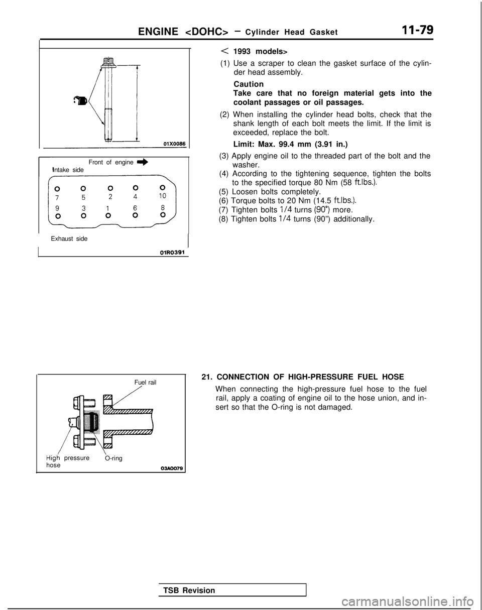
< 1993 models>
(1) Use a scraper to clean the gasket surface of the cylin- der head assembly.
Caution
Take care that no foreign material gets into the
coolant passages or oil passages.
(2) When installing the cylinder head bolts, check that the shank length of each bolt meets the limit. If the limit is
exceeded, replace the bolt.
Limit: Max. 99.4 mm (3.91 in.)
(3) Apply engine oil to the threaded part of the bolt and the washer.
(4) According to the tightening sequence, tighten the bolts
to the specified torque 80 Nm (58 ftlbs.).
(5) Loosen bolts completely.
(6) Torque bolts to 20 Nm (14.5 ftlbs.).
(7) Tighten bolts
l/4 turns (90”) more.
(8) Tighten bolts
l/4 turns (90”) additionally.
TSB Revision 21. CONNECTION OF HIGH-PRESSURE FUEL HOSE
When connecting the high-pressure fuel hose to the fuelrail, apply a coating of engine oil to the hose union, and in-
sert so that the O-ring is not damaged.
Page 130 of 1273
II-80ENGINE
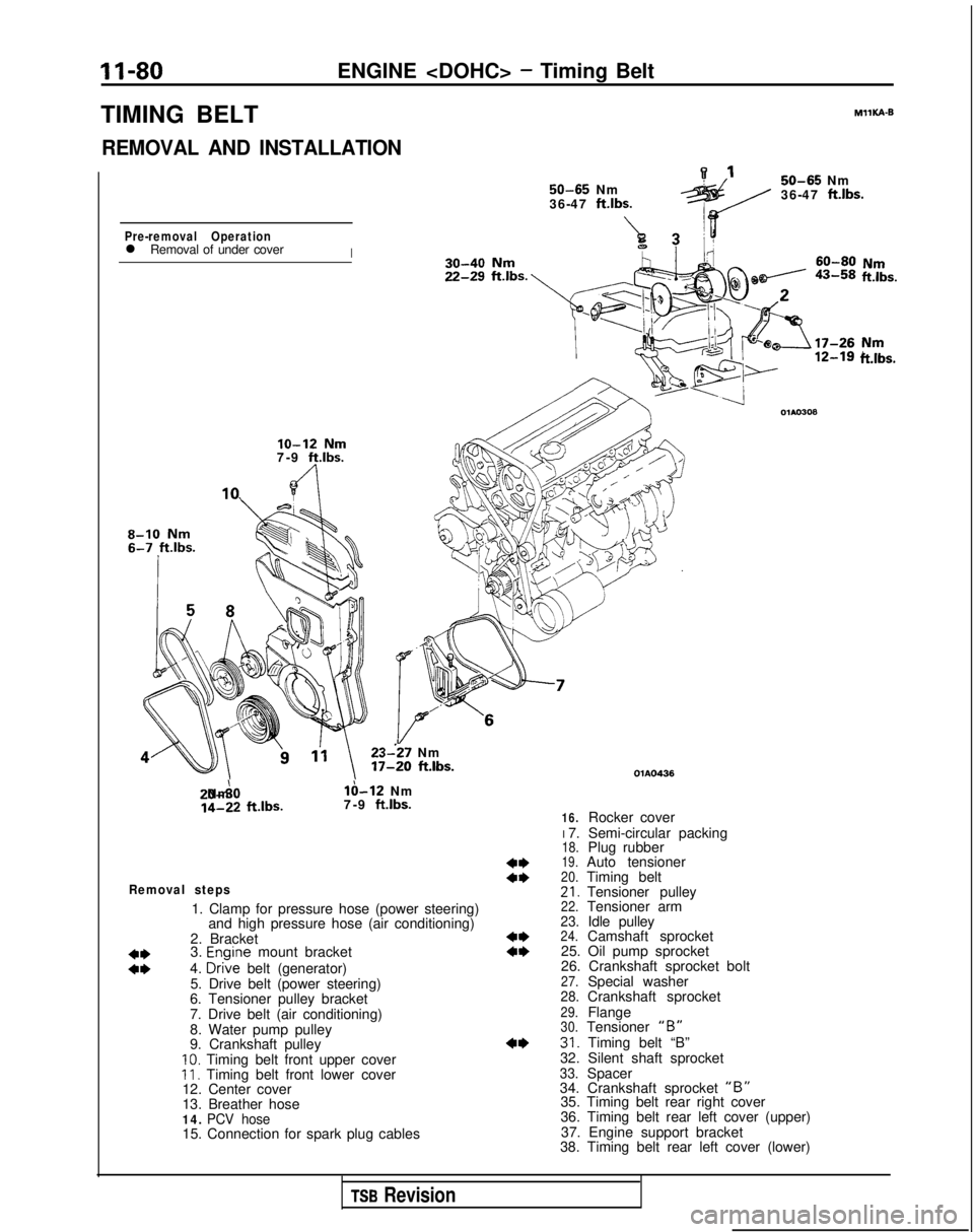
TIMING BELT
REMOVAL AND INSTALLATION 50-65
Nm
36-47 ftlbs.
A7Pre-removal Operationl Removal of under coverI MIlKA-B
50-65
Nm
36-47
ft.lbs.
ii!&.
lo-12 Nm7-9 ft.lbs.
8-10 Nm
23--27 Nm 17-20
ft.lbs. 20-A0 Nm
lb-12 Nm
14-22
ftlbs.
7-9 ft.lbs.
Removal steps
1. Clamp for pressure hose (power steering)
and high pressure hose (air conditioning)
2. Bracket
3.
Enoine mount bracket
ii4. D&e belt (generator)
5. Drive belt (power steering)
6. Tensioner pulley bracket
7. Drive belt (air conditioning)
8. Water pump pulley
9. Crankshaft pulley
10. Timing belt front upper coverII. Timing belt front lower cover
12. Center cover
13. Breather hose
14. PCV hose15. Connection for spark plug cables
ft.lbs.
4*a*
4**I)
4* OlAO436
16.Rocker cover
I 7. Semi-circular packing
18.Plug rubber19.Auto tensioner20.Timing belt21.Tensioner pulley22.Tensioner arm23.Idle pulley24.Camshaft sprocket
25. Oil pump sprocket
26. Crankshaft sprocket bolt
27.Special washer28.Crankshaft sprocket29.Flange30.Tensioner “B”31. Timing belt “B”
32. Silent shaft sprocket
33.Spacer
34. Crankshaft sprocket “B”35. Timing belt rear right cover
36. Timing belt rear left cover (upper)
37. Engine support bracket
38. Timing belt rear left cover (lower)
TSB Revision
Page 131 of 1273
ENGINE
f”.53A51b;m
r----v 1
3
lo-12 Nm
11-16
ftlbs.80-100
Nm y~x-di
58-72ft.lbs.2234!?!I
212543-55Nm 31-40, ff.lbs.b&-.,\‘-
/20-27 Nm
14-20
ftlbs.110;130 Nm80-94
ftlbs.
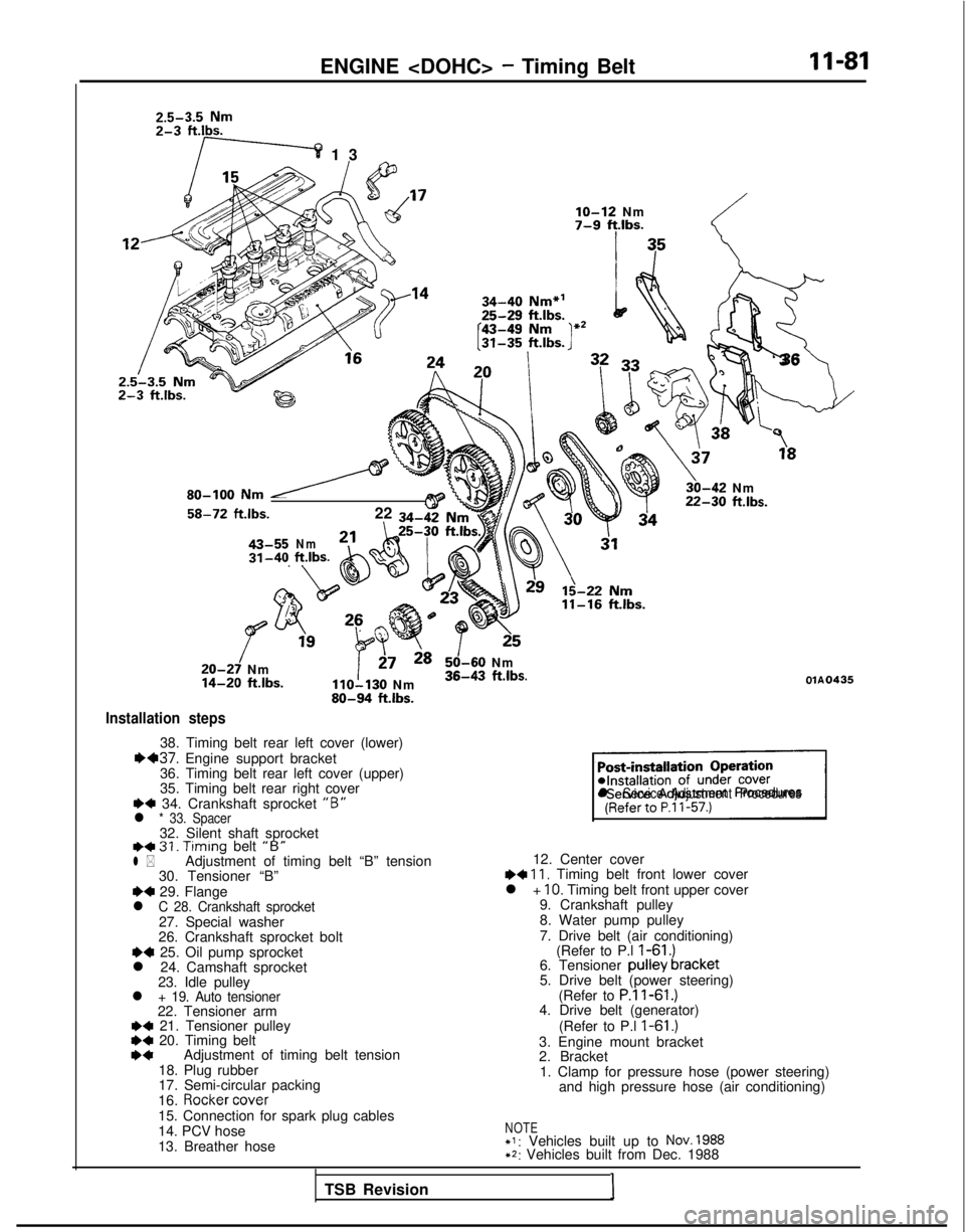
Installation steps
38. Timing belt rear left cover (lower)1H37. Engine support bracket
36. Timing belt rear left cover (upper)
35. Timing belt rear right cover
+4 34. Crankshaft sprocket “B”l * 33. Spacer32. Silent shaft sprocketI)+ 31. Timing
belt “B”l *Adjustment of timing belt “B” tension
30. Tensioner “B”
~~ 29. Flangel C 28. Crankshaft sprocket27. Special washer
26. Crankshaft sprocket bolt
~~ 25. Oil pump sprocket
l 24. Camshaft sprocket 23. Idle pulley
l + 19. Auto tensioner22. Tensioner arm+a 21. Tensioner pulley*C 20. Timing beltI)*Adjustment of timing belt tension
18. Plug rubber
17. Semi-circular packing
16.
Rocker cover
15. Connection for spark plug cables
14. PCV hose
13. Breather hose
!_-;
‘3
6
\
3,“”
30-42 Nm22-30 ftlbs.
125
50-60 Nm36-43 ftlbs.OlA0435
sl Service Adjustment Procedures
12. Center cover~~ 11, Timing belt front lower cover
l + IO. Timing belt front upper cover
9. Crankshaft pulley
8. Water pump pulley
7. Drive belt (air conditioning) (Refer to P.l
I-61 .)6. Tensioner pulley bracket
5. Drive belt (power steering)
(Refer to
P.ll-61.)4. Drive belt (generator)
(Refer to P.l
I-61 .)3. Engine mount bracket
2. Bracket1. Clamp for pressure hose (power steering) and high pressure hose (air conditioning)
NOTE+I: Vehicles built up to NOV. 1988+2: Vehicles built from Dec. 1988
TSB Revision I
Page 136 of 1273
11-86
ENGINE
Crankshaft
sprocket “B”
Crankshaft
6EN304 j
Spacer
I
ChamferedSilent shaft n
sprocket
I
Center oftenslonerpulley
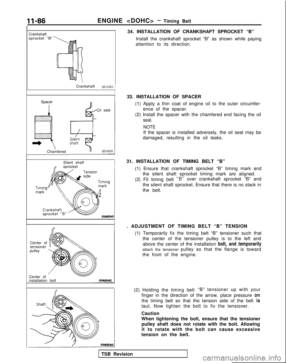
Center of installation bolt 34. INSTALLATION OF CRANKSHAFT SPROCKET “B”
Install the crankshaft sprocket “B” as shown while paying
attention to its direction.
33. INSTALLATION OF SPACER (1) Apply a thin coat of engine oil to the outer circumfer-ence of the spacer.
(2) Install the spacer with the chamfered end facing the oil
seal.
NOTE
If the spacer is installed adversely, the oil seal may be
damaged, resulting in the oil leaks.
31. INSTALLATION OF TIMING BELT “B” (1) Ensure that crankshaft sprocket “B” timing mark andthe silent shaft sprocket timing mark are aligned.
(2) Fit timing belt
“B” over crankshaft sprocket “B” and
the silent shaft sprocket. Ensure that there is no slack in
the belt.
. ADJUSTMENT OF TIMING BELT “B” TENSION (1) Temporarily fix the timing belt “B” tensioner such thatthe center of the tensioner pulley is to the left andabove the center of the installation bolt, and temporarily
attach the tensioner pulley so that the flange is toward
the front of the engine.
(2) Holding the timing belt “B” tensioner up with your
finger in the direction of the arrow, place pressure on
the timing belt so that the tension side of the belt is
taut. Now tighten the bolt to fix the tensioner.
Caution
When tightening the bolt, ensure that the tensioner pulley shaft does not rotate with the bolt. Allowing
it to rotate with the bolt can cause excessive
tension on the belt.
TSB Revision
Page 143 of 1273
13-1
FUEL
CONTENTSM’ISAA--
AUTO-CRUISE CONTROL SYSTEM.............
.
332
AUTO-CRUISE CONTROL ............................. 408
SERVICE ADJUSTMENT PROCEDURES .................397
Accelerator Cables
inspectron and Adjustment ........
.
398 Auto-cruise
Control System Inspection
..............397
Individual Parts Inspection ......................
401SPECfAL
TOOLS
.....................................
333
SPECIFICATIONS .................................... 332
TROUBLESHOOTING ................................. 334
Auto-cruise Control Components Location ..........368
Auto-cruise Control
Related Harnesses
..........365
Check Chart
Check Chart
Circuit Diagram ................................
371input Checking................................
.
366
On-board Diagnostic Checking ......................
361Troubleshooting Quick-reference Chart
.
334
Troubleshooting Quick-reference Chart
ENGINE CONTROL...............................
.
328
ENGINE CONTROL ..................................
330
SERVICE ADJUSTMENT PROCEDURES .................329
Accelerator Cable inspectron and Adjustment
...........329
Accelerator Switch Inspection and Adjustment ..........329
SPECIFICATIONS ....................................
328
TROUBLESHOOTlNG................................
.
328
Accelerator
Cable and Accelerator Pedal .............
.
328
FUEL SYSTEM
FUEL FILTER .........................................
327
FUEL LINE AND VAPOR LINE
.
326
FUEL LINE AND VAPOR LINE
.
324
FUEL TANK
.
322
FUELTANK
.
318
GENERAL INFORMATION ............................ 196
ON-VEHICLE INSPECTION OF MFI
COMPONENTS
......251
Air Conditioning Switch and A/C Compressor Clutch Relay .....................................
285
Barometric Pressure Sensor .................... 266
Boost Meter
311Camshaft Position Sensor ........................
.
277Closed Throttle Position Switch
.....................
.
274
Component Location .............................
251Components Inspection Pocedure
................. 255
Crankshaft Position Sensor ..................... 280EGR
Solenord
...................
.
307EGR Temperature Sensor
.............
.
288Engrne Control Module Power Ground
................
.
257
Engine Coolant Temperature Sensor ..................
268Evaporative Emission Purge Solenoid .................
.
307
Fuel Pressure Solenoid
307Fuel Pressure Test...............................
.
312
Fuel Pump ...................................... 258
Heated Oxygen Sensor ............................ 290
Idle Air Control Motor (Stepper Motor) ................
238Ignition Coil and Ignition Power Transistor .............
.
302
Ignition Switch-ST .................................. 284
Ignition Switch-ST and Park/Neutral Position Switch .....284
Injectors .......................................
295Inspection of Engine Control Module Terminal
Voltage .......................................
.
315
Intake Air Temperature Sensor .......................263
Knock Sensor
Power Steering Pressure Switch ......................
284Power Supply and Ignition Switch ...................
.
255Resistor
..............................
.
298Terminal Voltage Check Chart
......................
.
315Throttle Position Sensor
..........................
.
270Turbocharger Waste Gate Solenoid
.........
.
309 Vehicle
Speed Sensor
............................... 284
Volume Air Flow Sensor ............................
261SERVICE ADJUSTMENT PROCEDURES ...............
.
245
Basic
idle Speed Adjustment .......................
.
245
Closed Throttle Position Switch (Fixed
SAS)Adjustment ......................................
.
250
Curb
Idle Speed Inspection
..........................245Throttle Body (Throttle Valve Area) Cleaning
...........
.
248Throttle Position Sensor Adjustment
..................
.
248
SPECIALTOOLS...................................
.
204
SPECIFICATIONS ...................................
201TROUBLESHOOTING ...............................
.
205
Check Engine/Malfunction Indicator Lamp ..............205
Circuit Diagram .................................... 214
Clear Memory of Diagnostic Trouble Code .............
211Explanation and Precaution Related to Harness
Checking ......................................
.
205Explanation of Troubleshooting Procedures
............
.
205Failsafe/Back-up Functions List
.....................
.
211Fuel tank and Fuel Line
............................
.
244
Read Out Diagnostic Trouble Code ...................
211Troubleshooting Table
.............................
.
208(CONTINUED ON NEXT PAGE)
Page 144 of 1273
13-2
FUEL SYSTEM
..........
FUEL FILTER ....................................
FUEL LINE AND VAPOR LINE .....................FUELTANK....................................
.
GENERAL INFORMATION ........................
ON-VEHICLE INSPECTION OF MFI
COMPONENTS . .
Air
Conditionrng Switch and A/C CompressorClutch Relay ......
.
.............
Barometric Pressure Sensor .........
Camshaft Position Sensor ...........
Closed Throttle Position Switch ...........
Component Location .............
Components
Inspectron Procedure .......
.
Crankshaft Positron Sensor ............
EGR Solenoid
. . .3. .
115..,.113
. 109
. . 3
. . . 38
83
536961384173101EGR Temperature Sensor
.
85
Enqine Control Module Power Ground ......
.
....
45
Engine Coolant Temperature Sensor ...............
55Evaporative Emission Purge Solenord..............
.
99
Fuel Pressure ...............................
102Fuel Pump
...................................
.
46
Idle Speed Control Motor (DC Motor) ................
.
93
Idle Speed Control Motor Positron Sensor ............
.
64
lgnitron Co11 and Ignition Power Transistor .........
.
96
Ignition Switch-ST ..........................
77Ignition Switch-ST and Park/Neutral Position Switch
...78
Injectors..................................
.
90
Inspection of
Engrne Control Module Terminal
Voltage .........
.
..........................
105Intake Air Temperature Sensor ..................
.
51Oxygen Sensor
............................
.
87Power Steering Pressure Switch
..................
.
81Power Supply
.........................
.
42
Terminal Voltage Check Chart ......................
106Throttle Positron Sensor.....................
.
57Vehicle Speed Sensor
.........................
.
80
Volume Air Flow Sensor .........................
49
SERVICE ADJUSTMENT PROCEDURES .................
32
Basic
Idle Speed Adjustment ...................
.
33
Curb Idle Speed Inspection ..........................
32Throttle Body (Throttle Valve Area) Cleaning........
.
35
Throttle Positron Sensor Adjustment ................
35
SPECIAL TOOLS 7
.................
...................
SPECIFICATIONS ....................................
5
TROUBLESHOOTING .................................
8
Check Engine/Malfunction Indicator Lamp ..............
10Crrcuit Diagram.................................
.
20
Clear Memory of Diagnostic Trouble Code ............
17Explanation and Precaution Related to HarnessChecking......................................
.
9Explanation of Troubleshooting Procedures
...........
.
8
Failsafe/Back-up Functions List ....................
16Fuel Tank and Fuel Lrne.........................
.
32Read Out of Diagnostic Trouble Code
...............
.
16Troubleshooting Table
.........................
.
13
FUEL SYSTEM
116
FUEL FILTER .......................................
195
FUEL LINE AND VAPOR LINE ........................
195
FUEL TANK ........................................ 195
GENERAL INFORMATION ............................
116
ON-VEHICLE INSPECTION OF MFI
COMPONENTS
Air Conditioning Switch and A/C Compressor Clutch Relay .............................
Barometric Pressure Sensor .................
Camshaft Position Sensor ....................
Closed Throttle Position Switch ................
Component Location .......................
Components Inspectron Pocedure
..............
Crankshaft Position Sensor .................
EGR Solenoid
EGR Temperature Sensor
Engine Control Module Power Ground ..........
Engine Coolant Temperature Sensor .............
Evaporative Emission Purge Solenoid ............
Fuel Pressure Test ...........................
Fuel Pump ..................................
IAC Valve Positon Sensor
......................
Idle Air Control Motor (DC Motor) ..............
lgnrtion Coil and Ignition Power Transistor
.......
.
Ignition Switch-ST ...........................
Ignition Switch-ST and Park/Neutral Position Switch
Injectors ....................................
Inspection of Engine Control Module Terminal
Voltage .....................................
Intake Air Temperature Sensor .................
Oxygen Sensor .............................
Power Steering Pressure
Swatch..............
.
Power Supply ...............................
Terminal Voltage Check Chart ..................
Throttle Position Sensor .......................
Vehicle Speed Sensor ......................... . . . . 139
176
154
165
16013914216
7
..,_ 191177146
155
189192
147
162
184
186
171172181
192152
179
175
143
192
157
173
Volume Air Flow Sensor ...........................
.
150
SERVICE ADJUSTMENT PROCEDURES
...............
.
133
Basic Idle Speed Adjustment 133
Closed Throttle Position Switch and Throttle Position
Sensor Adjustment .................................
136Curb Idle Speed Inspection
.........................
.
133Fixed SAS Adjustment
.............................
.
138Throttle Body (Throttle Valve Area) Cleaning
...........
.
136
SPECIAL TOOLS
...................................
.
119
SPECIFICATIONS 118
.... ..............................
TROUBLESHOOTING ..................
.............
119
Check Engine/Malfunction Indicator Lamp ..............
120Circuit Diagram...................................
.
128Clear Memory of Diagnostic Trouble Code
............
.
126Explanation and Precaution Related to Harness
Checking ........................................
.
119Explanation of Troubleshooting Procedures
............
.
119Failsafe/Back-up
Fuctions List
........................
126
Fuel Tank and Fuel Line .............................
133Read Out of Diagnostic Trouble Code ................
.
126
Troubleshooting Table ..............................
123
Page 148 of 1273
13-6
FUEL SYSTEM
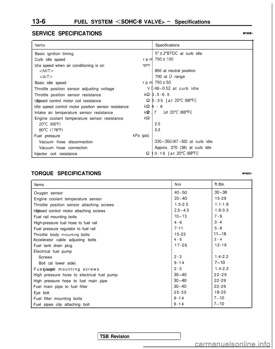
SERVICE SPECIFICATIONSMl3CE.
ItemsSpecifications
Basic ignition timing
5”?2”BTDC at curb idle
Curb idle speed rpm
7502 100Idle
speed when air conditioning is on rpm
-am-r>850 at neutral position
4A>700 at D range
Basic idle speed rpm
750+50
Throttle position sensor adjusting voltageV 0.48-0.52 at curb idl
e
Throttle position sensor resistance
k-2 3.5-6.
5
Idle speed control motor coil resistance
Q 5-35 [at 20°C (68”F)l
Idle
speed control motor position sensor resistance
M-2 4-
6
Intake air temperature sensor resistance kQ 2.7 [at
20°C (68”F)l
Engine coolant temperature sensor resistancekc2
20°C (68°F)2.5
80°C (176°F)0.3
Fuel pressurekPa (psi)
Vacuum hose disconnection
330-350 (47-50) at curb idle
Vacuum hose connection Approx. 270 (38) at curb idle
Injector coil resistance
R 13-16 [at 20°C (68”F)]
TORQUE SPECIFICATIONSMIICC-
Items
Oxygen sensor
Engine coolant temperature sensor
Throttle position sensor attaching screws Idle speed control motor attaching screws
Fuel rail mounting bolts
High-pressure fuel hose to fuel rail
Fuel pressure regulator to fuel rail
Throttle body mounting
bolts
Accelerator cable adjusting bolts
Fuel tank drain plug
Electrical fuel pump Screws
Bolt (at lower side)
Fuel unit mounting screws gauge
High pressure hose to electrical fuel pump
High pressure hose to fuel main pipe
Fuel main pipe to fuel filter
Eye bolt
Fuel filter mounting bolts
Fuel pipes clip attaching boltNmft.lbs.
40-5030-36
20-4015-29
1.5-2.5 1.1-1.8
2.5-4.51.8-3.3
IO-137-
9
4-6 3-4
7-11 5-8
15-22
11-16
4-
6
3-4
17-26 12-19
2-3 1.4-2.2
9-14
7-10
2-
3
1.4-2.2
30-4022-2
9
30-4022-29
30-4022-29
25-3
5
18-25
9-14
7-10
9-1
4
7-10
1 TSB Revision