1988 PONTIAC FIERO check engine
[x] Cancel search: check enginePage 995 of 1825
700-R4-6 HYDRAULIC DIAGNOSIS
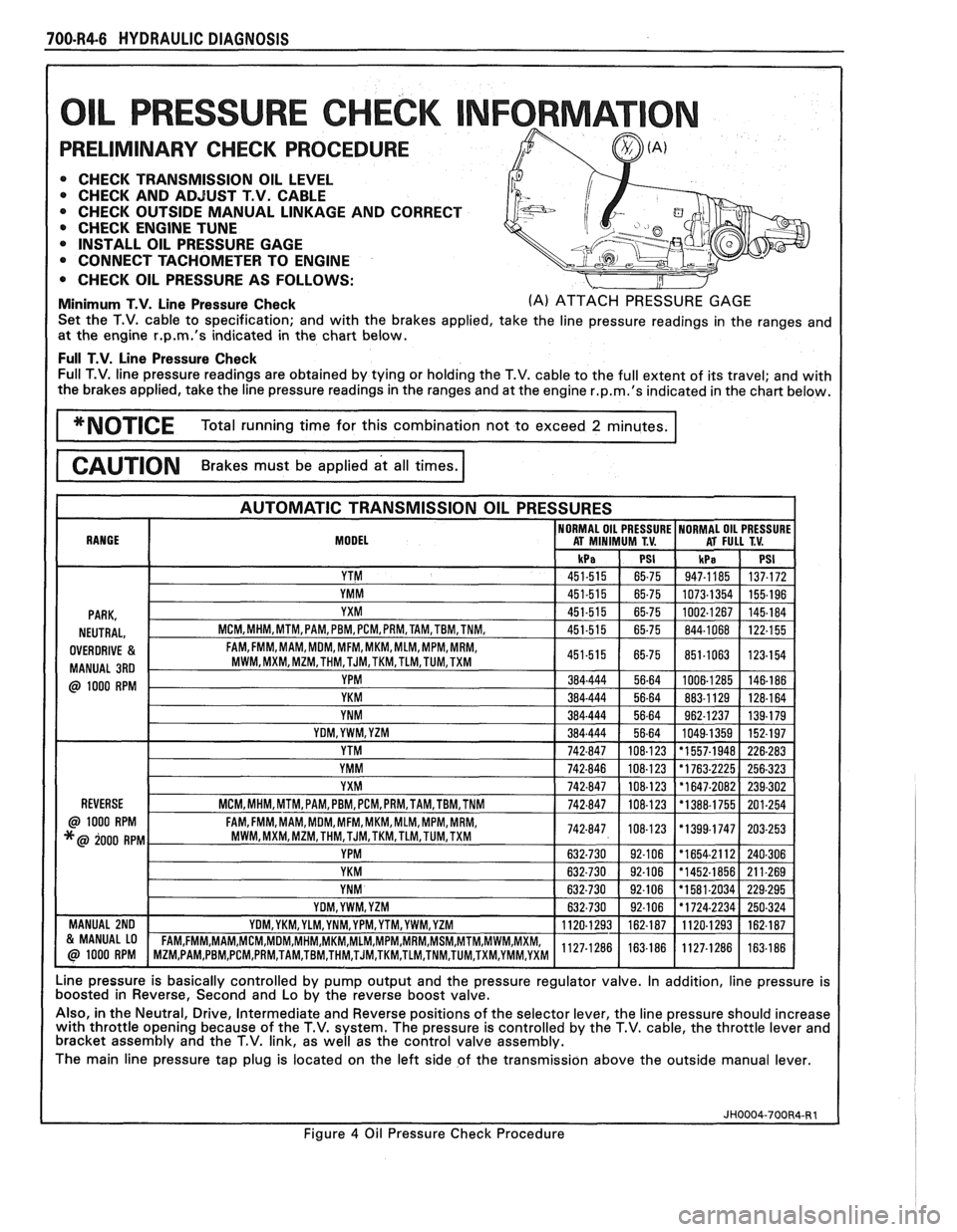
L PRESSURE CHECK NFORMAT
PRELIMINARY CHECK PROCEDURE
0 CHECK TRANSMISSION OIL LEVEL 0 CHECK AND ADJUST T.V. CABLE
0 CHECK OUTSIDE MANUAL LINKAGE AND CORRECT
@ CHECK ENGINE TUNE
0 INSTALL OIL PRESSURE GAGE
CONNECT TACHOMETER TO ENGINE
0 CHECK OIL PRESSURE AS FOLLOWS:
Minimum T.V. Line Pressure Check (A) ATTACH PRESSURE GAGE
Set the T.V. cable to specification; and with the brakes applied, take the line pressure readings in the ranges and
at the engine
r.p.m.'s indicated in the chart below.
Full T.V. Line Pressure Check Full T.V. line pressure readings are obtained by tying or holding the T.V. cable to the full extent of its travel; and with
the brakes applied, take the line pressure readings in the ranges and at the engine
r.p.m.'s indicated in the chart below.
MODEL
Line pressure is basically controlled by pump output and the pressure regulator valve. In addition, line pressure is
boosted in Reverse, Second and Lo by the reverse boost valve.
Also, in the Neutral, Drive, Intermediate and Reverse positions of the selector lever, the line pressure should increase
with throttle opening because of the T.V. system. The pressure is controlled by the T.V. cable, the throttle lever and
bracket assembly and the T.V. link, as well as the control valve assembly.
The main line pressure tap plug is located on the left side of the transmission above the outside manual lever.
Figure
4 Oil Pressure Check Procedure
Page 997 of 1825
700-R4-8 HYDRAULIC DIAGNOSIS
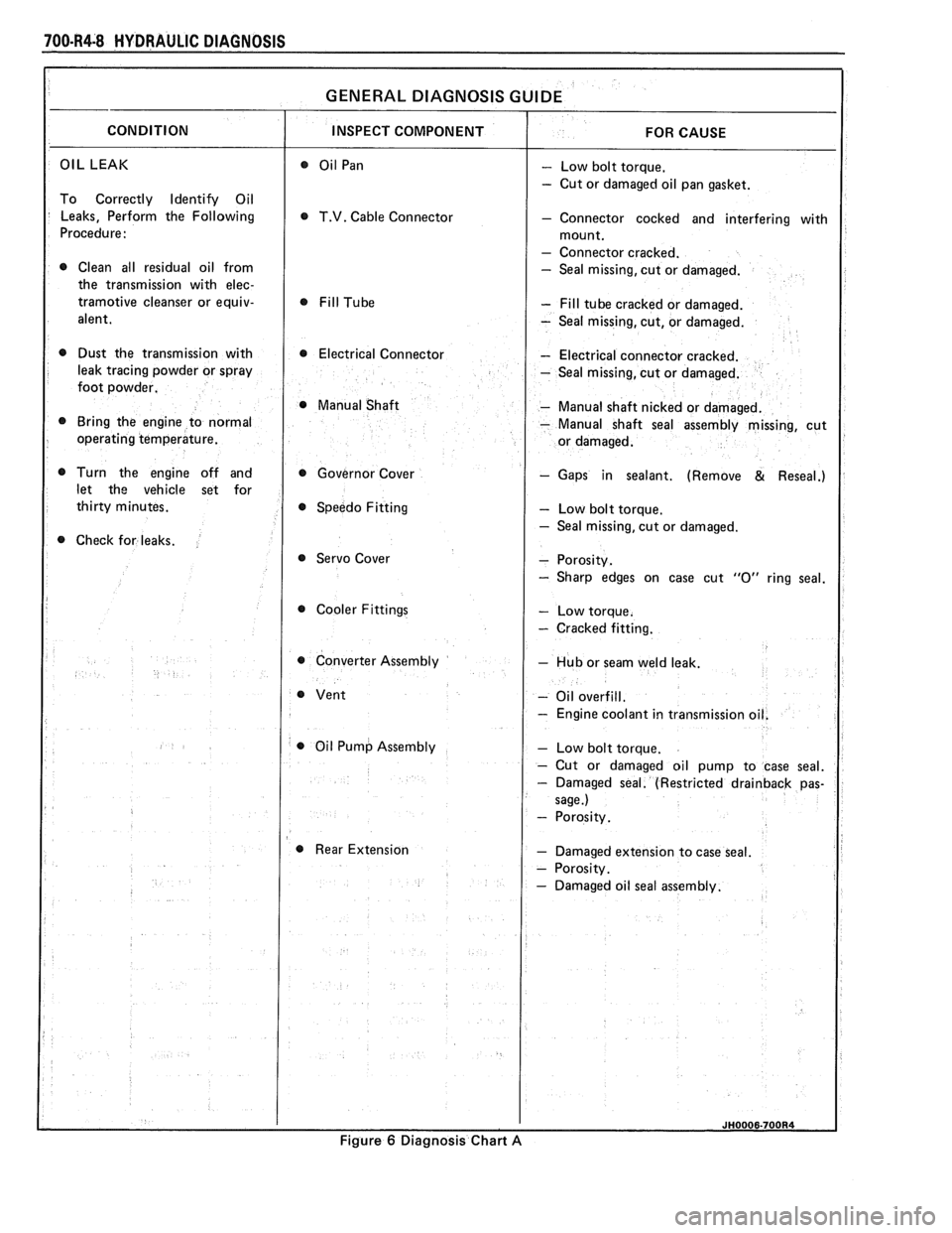
OIL LEAK - Low bolt torque.
- Cut or damaged oil pan gasket.
To Correctly Identify Oil
Leaks, Perform the Following
T.V. Cable Connector - Connector cocked and interfering with
Procedure:
- Connector cracked.
0 Clean all residual oil from - Seal missing, cut or damaged.
the transmission with
elec-
tramotive cleanser or equiv- - Fill tube cracked or damaged.
alent.
- Seal missing, cut, or damaged.
0 Dust the transmission with 0 Electrical Connector - Electrical connector cracked.
leak tracing powder or spray
- Seal missing, cut or damaged.
foot powder.
@ Manual Shaft - Manual shaft nicked or damaged.
Bring the engine to normal
- Manual shaft seal assembly missing, cut
operating temperature.
Turn the engine off and Governor Cover
- Gaps in sealant. (Remove & Reseal.)
let the vehicle set for
Speedo Fitting
- Low bolt torque.
- Seal missing, cut or damaged.
Check for leaks.
@ Servo Cover
Cooler Fittings
- Cracked fitting.
0 Converter Assembly - Hub or seam weld leak.
- Oil overfill.
- Engine coolant in transmissio
0 Oil Pump Assembly
Rear Extension
- Damaged extension to case seal.
Figure
6 Diagnosis Chart A
Page 999 of 1825
100.R4.10 HYDRAULIC DIAGNOSIS
(Verify With Gage-Check - Rotor guide omitted or misassembled.
Oil Level
81 Engine Tune.) - Rotor cracked or broken. - T.V. valve, reverse boost valve or bushing
stuck, damaged or incorrectly assembled.
- Orifice hole in pressure regulator valve
- Sticking slide or excessive rotor clearance.
- Pressure relief ball not seated or damaged.
- Porosity in pump cover or body.
- Wrong pump cover.
- Pump faces not flat.
- Excessive rotor clearance.
- Intake pipe restricted by casting flash.
- Cracks in filter body or intake pipe.
- "0" ring seal missing, cut or damaged.
- Wrong grease used on rebuild.
T.V. Exhaust Ball
- Stuck or damaged.
* Throttle Link - Misassembled, binding or damaged.
- Manual valve scored or damaged.
- Spacer plate or gaskets incorrect, mis-
assembled or damaged.
- Face not flat.
- Throttle valve sticking.
- T.V. limit valve sticking.
- Modulated downshift valve stuck.
- Line bias valve stuck.
- 2-3 Shift valve stuck.
- Check balls omitted or misassembled.
- Case to valve body face not flat.
T.V. Exhaust Ball
- Stuck or damaged.
Throttle Lever
81 Bracket - Misassembled, binding or damaged.
Figure
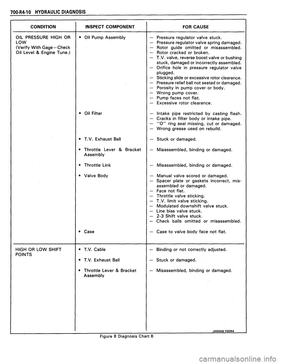
8 Diagnosis Chart B
Page 1020 of 1825
HYDRAULIC DfAQNOSIS 70044-31
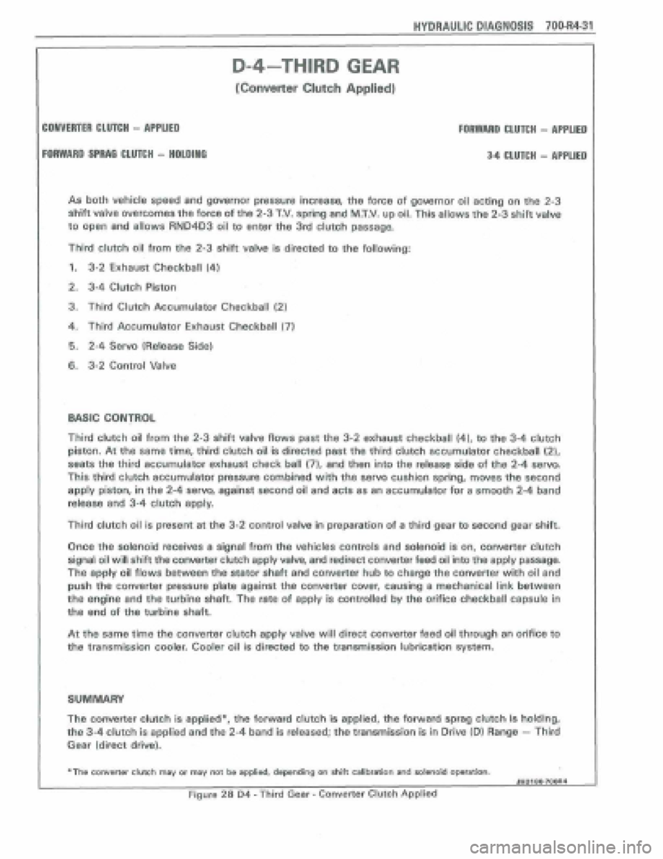
As both vehicle speed and governor pressure increase, the force of gowrnor oil acting on the 2-3
shift valve overcomes the force of the 2-3 T.V. spring and MXV. up oil, This allows the 2-3 shift valve
to
open and allows RN04D3 oil to enter the 3rd clutch passage.
Third clutch oil from the 2-3 shift valve is directed to the following:
1. 3-2 Exhaust Checkball (4)
2. 3-4 Clutch Piston
3. Third Clutch Accumulator Checkball (2)
4. Third Accumulator Exhaust: Checkball (7)
6. 2-4 Servo 1Release Side)
6. 3-2 Control Valve
D-4-THIRD GEAR
[Converter CItPtch Applied)
COMVERTER CtUTCli - APPLIED FOAWARD CLUTCH - APPLIED
FORWARD SFRAG CLU7CH - HPLDINO 34 CLUTCH - APPLIED
Third clutch oil from the 2-3 shift valve flows past the 3-2 exhaust checkball (4), to the 3-4 clutch
piston. At the same time, third clutch oil is directed past the third clutch accumulator checkball {2),
seats the third accumula'tor exhaust check ball (71, and then into the release side of the 2-4 serva
This third clutch accumulator pressure combined with the servo cushion spring, moves the second
apply piston, in the 2-4 servo, against second oil and acts as an accumulator for a smooth 2-4 band
release and 3-4 clutch apply.
Third clutch oil is present at the 3-2 control valve In preparation of a third gear to second gear shift.
Once the solenoid teceives a signal from the vehicles controls and solenoid is on, convefier clutch
signal oil will shift the converter clutch apply valve, and redirect converter feed oil into the apply passage.
the apply oil flows between the stator shaft and converter hub to charge the converter with oil and
push the converter pressure plate against the converter cwer, causing a mechanical link between
the engine and the turbhe shaft. The rate of apply is controlled by the orifice checkball capsule in
tha end of the turbine shaft.
At tho same time the converter clutch appfy valve will direct converter feed oil through an orifice to
the transmission cooler. Cooler oil is directed to the transmission lubrication sysm.
SUMMARY
The converter clutch is applied*, the forward clutch is applied, tho forward sprag clutch is holding,
the 3-4 clutch is applied and the 2-4 band is released; the transmission is in Drive (Dl Range - Third
Gear (direct drive).
+The converter clwh msy or may not be applied, depending on Aitt calibration and salenoid operation. JHOI 80+7OOA4
Figure 28 D4 - Third Gear - Converter Clutch Applkd
Page 1028 of 1825
HYDRAULIC DIAGNOSIS 70044-39
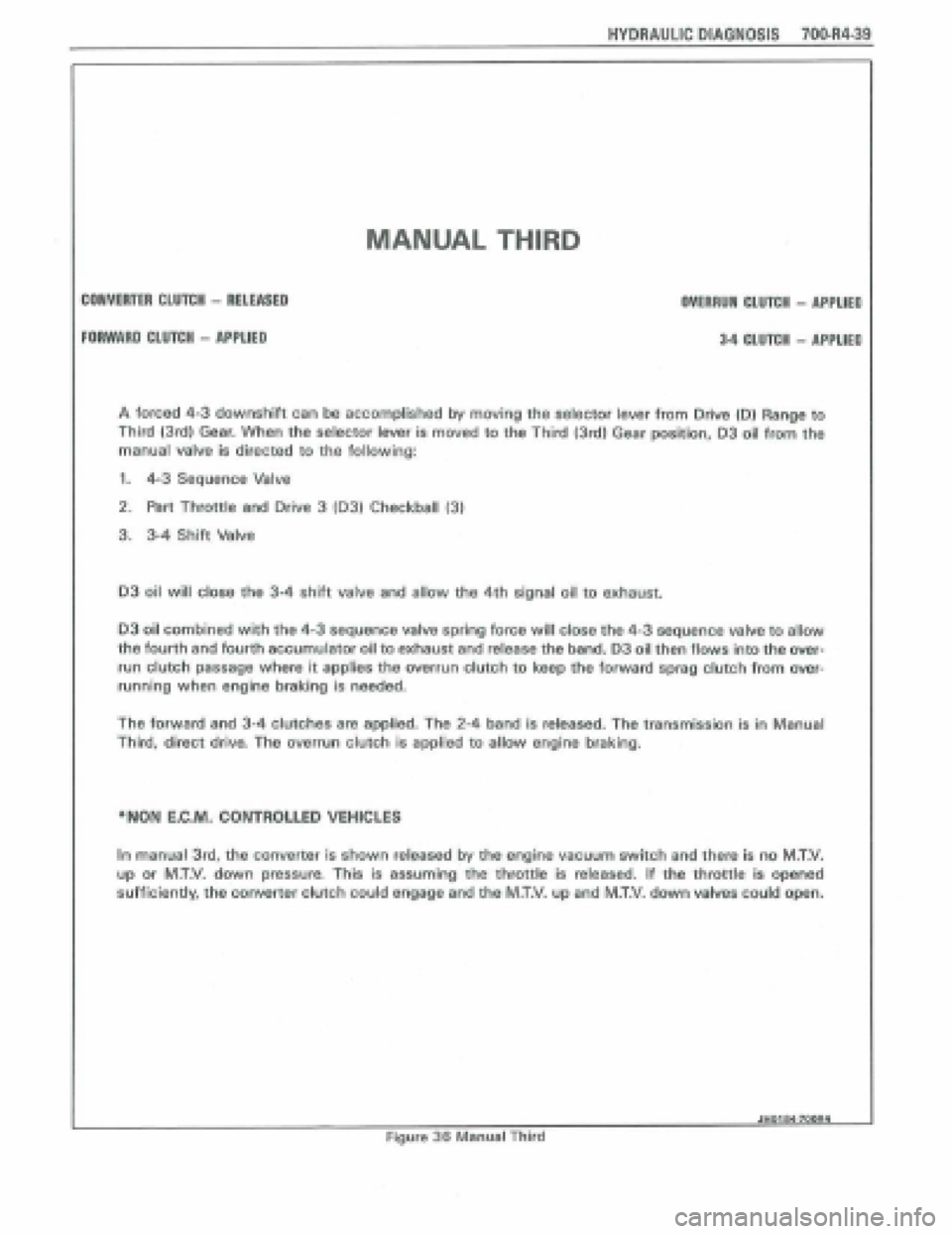
MANUAL THIRD
CONVERTER CLUTCH - RELEASED
FORWARD CLUTCH - APPLIED
OVERRUN CLUTCH - APPUED
3.4 CLUfeH - APPLIEP
A forced 4-3 downshift can be accomplished by moving the selector lever from Drive 10) Range to
Third {3rd) Gear. When the selector lever is moved to the Third (3rd) Gear position, 03 oil from the
manual
valve is directed to the following:
1. 4-3 Sequence Valve
2. Part Throttle and Drive 3 103) Checkball 131
3. 3-4 Shift Valve
03 oil will close the 34 shift valve and allow the 4th signal oil to exhaust.
D3 oil combined with the 4-3 sequence valve spring force will close the 4-3 sequence valve to allow
the fourth and fourth accumulator oil to exhaust and release the band. 03 oil then flows into the over-
run clutch passage where it applies the overrun clutch to keep the forward sprag clutch from over-
running when engine braking is n~eded.
The forward and 3-4 CIU~C~~S are applied. The 2-4 band is released. The transmission is in Manual
Third,
direct driva The overrun clutch is appRad to allow engine braking.
*NON E,C.M, CONTROLLED VEHICLES
In manual 3td, the converter is shown released by the engine vacuum switch and there is no M.T.V.
up or M.T.V. down pressure, This is assuming the throttle is released. If the throttle is opened
sufficiently, the converter clutch could engage and the M.T.V. up and MXV. down valves coJd open.
JHOtOQ7WRI I
Figure 36 Manual Third
Page 1050 of 1825
TORQUE CONVERTER CLUTCH (TCC)
DIAGNOSIS
To properly diagnose the Torque Converter
Clutch (TCC) system, perform all electrical
testing first and then the hydraulic testing. Refer
to the Torque Converter Section
6E2-C8 for
additional information.
The TCC is applied by fluid pressure which is
controlled by a solenoid located inside the Automatic
Transmission assembly. The solenoid is energized or
released by making or breaking an electrical circuit
through a combination of switches and sensors.
TCC Electrical Diagnosis
e For electrical diagnosis of TCC, refer to the
specific vehicle section in Section
8A, Electrical
Diagnosis.
e For diagnosis of emission control related
components of TCC, Refer to the specific section
of
6E, Driveability and Emissions.
e For the diagnosis of TCC Hydraulic Controls,
refer to the Procedure and Wiring Diagrams
provided in this section.
Functional Check Procedure
rn Inspect
1. Install a tachometer
2. Operate the vehicle until proper operating
temperature is reached
3. Drive vehicle at 50-55 mph (80-88 Km/h) with
light throttle (road load)
4. Maintaining throttle lightly touch the brake
pedal and check for a slight bump when the TCC
releases and a slight increase in engine RPM.
5. Release the brake, slowly accelerate and check for
a re-apply of the converter clutch and a slight
decrease in engine RPM.
Preliminary Checking Procedure
The purpose of the preliminary checking
procedure is to isolate external (electrical) problems
from internal (electrical or mechanical) ones.
Important
e Use only a scale type ohmmeter. High impedance
type ohmmeters and those with a digital readout
will not work.
e An ALCL scanner may be used to verify the
electrical circuit. Remember, a completed circuit
does not indicate that the solenoid will apply.
e Do not bench test using an automotive type
battery. Accidentally crossed wires will damage
the internal diodes of the TCC solenoid.
HYDRAULIC DIAGNOSIS 700-R4-61
External Controls
rn Inspect
e Connect voltmeter between transmission
connector and ground.
e Turn key "ON"
e If 0 or low voltage is found, refer to Sections 6E
and 8A for electrical diagnosis.
e If 12 volts are present at the connector, refer to
the TCC hydraulic diagnosis.
TORQUE CONVERTER EVALUATION
Torque Converter Stator
The Torque Converter Stator roller clutch can
have one of two different type malfunctions:
A. Stator Assembly freewheels in both
directions.
B. Stator Assembly remains locked up at all
times.
Condition A-Poor Acceleration Low Speed
The vehicle tends to have poor acceleration from
a standstill. At speeds above 30-35 mph (50-55
km/h),
the car may act normal. If poor acceleration is noted,
it should first be determined that the exhaust system
is not blocked, the engine timing is correct and the
transmission is in first
(1st) gear when starting out.
If the engine freely accelerates to high
r.p.m. in
"NEUTRAL" (N), it can be assumed that the engine
and exhaust system are normal. Checking for poor
performance in "Drive" and Reverse will help
determine if the stator is freewheeling at all times.
Condition B-Poor Acceleration High Speed
Engine r.p.m. and car speed limited or restricted
at high speeds. Performance when accelerating from a
standstill is normal. Engine may over-heat. Visual
examination of the converter may reveal a blue color
from over-heating.
If the converter has been removed, the stator
roller clutch can be checked by inserting a finger into
the splined inner race of the roller clutch and trying to
turn the race in both directions. The inner race should
turn freely clockwise, but not turn or be very difficult
to turn counterclockwise.
The Converter Should Be Replaced If:
e Leaks externally, such as at the hub weld area.
e Converter has an imbalance which cannot be
corrected. (Refer to Converter Vibration Test
Procedure).
e Converter is contaminated with engine coolant
containing antifreeze.
The Converter Should Not Be Replaced If:
e The oil has an odor, is discolored, and there is no
evidence of metal or clutch facing particles.
e The threads in one or more of the three converter
bolt holes are damaged.
- Correct with thread insert. (Refer to Section
6A).
Page 1118 of 1825
AUTOMATIC TRANSMISSION 7A-3
PRELIMARY CHECKING PROCEDURE
The condition of an automatic transmission not
operating properly may be influenced by one, or a
combination of the following items:
e Fluid level high/low
(Refer to Section 7A1)
e Engine performance
(Refer to Sections 6 and 6E)
T.V. cable adjustment
(Refer to Section
7A1)
e Manual linkage adjustment
(Refer to Section
7A1)
e Internal fluid leaks
(Refer to Transmission Unit Repair section)
e Electrical system
(Refer to Section 6E and 8A)
e Transmission or other mechanical component
(Refer to Transmission Unit Repair section)
e Vacuum modulator
(Refer to appropriate Hydraulic Diagnosis
Section)
NOISE AND VIBRATION ANALYSIS
A noise or vibration that is noticeable when the
vehicle is in motion, MAY NOT be the result of the
transmission.
If noise or vibration is noticeable in "Park"
(P)
and "Neutral" (N) with engine at idle, but is less
noticeable as
RPM's increase, the cause may be from
poor engine performance.
e Tires for
- Uneven wear
- Imbalance
- Mixed sizes
- Mixed radial and bias ply
(Refer to Section 3E)
e Suspension components for
- Alignment and wear
- Loose fasteners
(Refer to Section 3C)
e Engine/Transmission mounts for
- Damage
- Loose bolts
(Refer
to Sections 6A and 7A2)
e Transmission case mounting holes for:
- Missing bolts, nuts, studs
- Stripped threads
- Cracks
e Flywheel for:
- Missing or loose bolts
- Cracks
- Imbalance
(Refer to Section 6A)
e Torque converter for: - Missing or loose bolts or lugs - Missing or loose balance weights
- Imbalance
TRANSMISSION FLUID LEVEL INFORMATION
Checking fluid level, color and condition at
regular intervals will provide early diagnosis
information about the transmission. This information
may then be used to correct a condition that, if not
detected early, could result in major transmission
repairs.
When adding or changing fluid, use only
DEXRONO 11, or equivalent. Refer to Section OB of
this Service Manual for maintenance information and
servicing intervals.
Fluid level should be checked when it reaches
normal operating temperatures of
190-200°F.
(88-93°C). This temperature is reached after
approximately 15 miles (24 km) of highway
driving.
e Fluid color - Should be dark red (may be dark green)
NOTICE: Do not overfill. Overfilling will cause
foaming, loss of fluid and possible damage to the
transmission.
Inaccurate fluid level readings will result if
checked immediately after the vehicle has been
operated:
- In high abmient temperatures above 90°F
(32°C)
- At sustained high speeds
- In heavy city traffic during hot weather
- As a towing vehicle - In commercial service (taxi or police use)
TRANSMISSION FLUID CHECKING
PROCEDURE
(Refer to Figure 3)
1. Park vehicle on level ground.
2. Apply parking
brake and block wheels.
3. Start
engine and operate vehicle for 15 minutes or
until a normal operating temperature is reached.
4. Move gear
selector through all gear positions.
5. Move
gear selector to "Park" (P).
6. Check fluid level, color and condition.
Page 1121 of 1825
7A1-2 AUTOMATIC TRANSMISSION ON-VEHICLE SERVICE
Pitting
FLEXPLATE/TORQUE CONVERTER VIBRATION
TEST PROCEDURE
1. Start engine
2. With engine at idle speed and the transmission in
"Park"
(P) or "Neutral" (N), observe vibration.
3. Shut off engine.
Remove or Disconnect
e Flexplate cover attaching bolts
s Flexplate to torque converter attaching
bolts
e Rotate torque converter 120 (1/3 turn)
Install
or Connect
e Flexplate to torque converter attaching
bolts
- Torque bolts to 47 N.m (35 Ibs. ft.)
s Flexplate cover bolts
- Torque bolts to 6 N-m (53 lbs. in.)
4. Start engine and check for vibration. Repeat this
procedure un
ti1 the best possible balance is
obtained.
NOTICE: Some engine/transmission
combinations cannot be balanced in this manner
due to limited clearances between the torque
converter bolts and engine. Be sure bolts do not
bottom out in lug nuts or the torque converter
cover could be dented and cause internal damage.
FLUID LEAK DIAGNOSIS
The cause of most external leaks can generally be
located and repaired with the transmission in the car.
METHODS FOR LOCATING LEAKS
General Method
s Verify that the leak is transmission fluid.
a Thoroughly clean the suspected leak area.
s Operate the car for about 15 miles or until normal
operating temperatures are reached.
e Park the car over clean paper or cardboard.
s Shut off engine and look for fluid spots on paper.
a Make necessary repairs.
Powder Method
e Thoroughly clean the suspected leak area with
solvent.
a Apply an aerosol type powder (foot powder) to
the suspected leak area.
s Operate the car for about 15 miles or until normal
operating temperatues are reached.
s Shut off engine.
e Inspect suspected leak area and trace the leak
path through the powder to find the source.
a Make necessary repairs.
Dye And Black Light Method
A fluid dye and black light kit is available from
various tool manufacturers.
s Follow the manufacturer's recommendations for
the amount of dye to be used.
a Detect the leak with the black light.
e Correct cause of leak.
REPAIRING THE LEAK
Once the leak has been pinpointed and traced
back to its source, the cause of the leak must be
determined in order for it to be repaired properly. If a
gasket is replaced, but the sealing flange is bent, the
new gasket will not repair the leak. The bent flange
must be repaired also. Before attempting to repair a
leak, check to be sure that the following conditions are
correct as they may cause a leak.
Gaskets
s Fluid level/pressure is too high.
e Plugged vent or drain-back holes.
s Improperly torqued fasteners or dirty/damaged
threads.
a Warped flanges or sealing surface.
e Scratches, burrs or other damage to the sealing
surface.
e Damaged or worn gasket.
e Cracking or porosity of the component.
s Improper sealant used (where applicable).
Seals
e Fluid level/pressure is too high.
a Plugged vent or drain-back holes.
s Damaged seal bore (scratched, burred or nicked).
e Damaged or worn seal.
e Improper installation.
a Cracks in component.
e Manual or output shaft surface scratched, nicked
or damaged.
a Loose or worn bearing causing excess seal wear.
Possible Points of Oil Leak
I. Transmission/Transmission oil pan :
Attaching bolts not correctly torqued
s Improperly installed or damaged gasket
s Oil pan or mounting face not flat
2, Case Leak :
@ Filler pipe "multi-lip seal" damaged or
missing
a Filler pipe bracket mislocated
s T.V. cable "multi-lip" seal missing,
damaged or improperly installed
a Governor cover or "0" ring damaged or
missing
@ Speedometer driven gear/speed sensor seal
damaged
e Manual shaft seal damaged
s Oil cooler connector fittings loose or
damaged