1988 PONTIAC FIERO check engine
[x] Cancel search: check enginePage 1358 of 1825
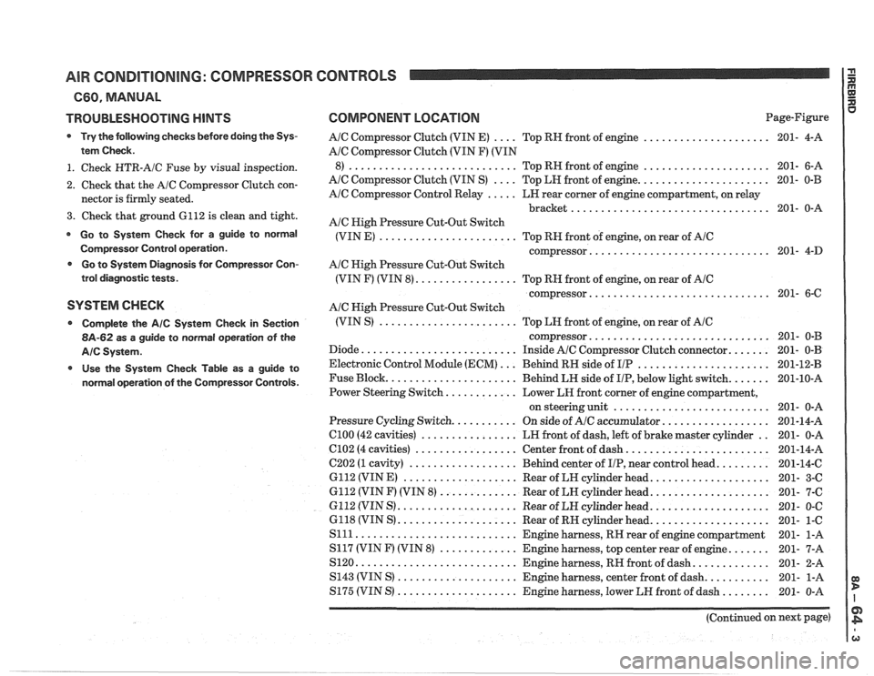
AIR CONDITIONING: COMPRESSOR CONTROLS
660. MANUAL
TROUBLESHOOTING
HINTS
Try the following checks before doing the Sys-
tem Check
.
1 . Check HTR-A/C Fuse by visual inspection .
2 . Check that the A/C Compressor Clutch con-
nector is firmly seated
.
3 . Check that ground 6112 is clean and tight .
Go to System Check for a guide to normal
Cornpressor Control operation
.
Go to System Diagnosis for Compressor Con-
trol diagnostic tests
.
SYSTEM CHECK
Complete the AIC System Check in Section
8A-62 as a guide to normal operation of the
AIC Systern .
Use the System Check Table as a guide to
normal operation of the Compressor Controls
.
COMPONENT LOCPaTlON Page-Figure
.... ..................... AIC Compressor Clutch (VIN E)
Top RH front of engine 201-
4-A
Ale Compressor Clutch (VIN F) (VIN
..................... ............................ 8) Top RH front of engine 201- 6-A
.... ...................... AlC Compressor Clutch (VIN S)
Top LH front of engine 201- 0-B
..... AIC Compressor Control Relay
LH rear corner of engine compartment. on relay
................................. bracket 201- 0-A
A/C High Pressure Cut-Out Switch
....................... (VIN E)
Top RH front of engine. on rear of AIC
.............................. compressor 201- 4-D
Ale Nigh Pressure Cut-Out Switch
................. (VIN F) (VIN 8) Top RN front of engine. on rear of AIC
.............................. compressor 201- 6-C
AIC High Pressure Cut-Out Switch
....................... (VIN S)
Top LH front of engine. on rear of AIC
.............................. compressor 201- 0-B
Diode
.......................... Inside AIC Compressor Clutch connector ....... 201- 0-B
Electronic Control Module (ECM)
... Behind RH side of I/P ...................... 201-12-B
Fuse Block
...................... Behind LH side of IIP. below light switch ....... 201-10-A
............ Power Steering Switch
Lower LR front corner of engine compartment.
.......................... on steering unit 201- 0-A
.................. Pressure Cycling Switch ........... On side of AlC accumulator 201-14-A
.. el00 (42 cavities) ................ LH front of dash. left of brake master cylinder
201- 0-A
........................ 6102 (4 cavities) ................. Center front of dash 201-14-A
......... C202 (1 cavity) .................. Behind center of IIP. near control head
201-14-C
6112 (VINE)
................... Rear of LH cylinder head .................... 201- 3-C
6112 (VIN F) (VIN 8)
............. Rear of LH cylinder head .................... 201- 7-C
G112 (VIN
S) .................... Rear of LH cylinder head .................... 201- 0-C
6118 (VIN S) .................... Rear of RH cylinder head .................... 201- 1-C
S111 ........................... Engine harness. RN rear of engine compartment 201- 1-A
S117 (VIN
F) (VIN 8) ............. Engine harness. top center rear of engine ....... 201- 7-A
S120
........................... Engine harness. RH front ofdash ............. 201- 2-A
........... S143 (VIN S) .................... Engine harness. center front of dash
201- 1-A
S175 (VIN S) .................... Engine harness. lower LH front of dash ........ 201- 0-A
(Continued on next page)
Page 1359 of 1825
AIR CONDITIONING: COMPRESSOR CONTROLS OD D
C60. MANUAL I I
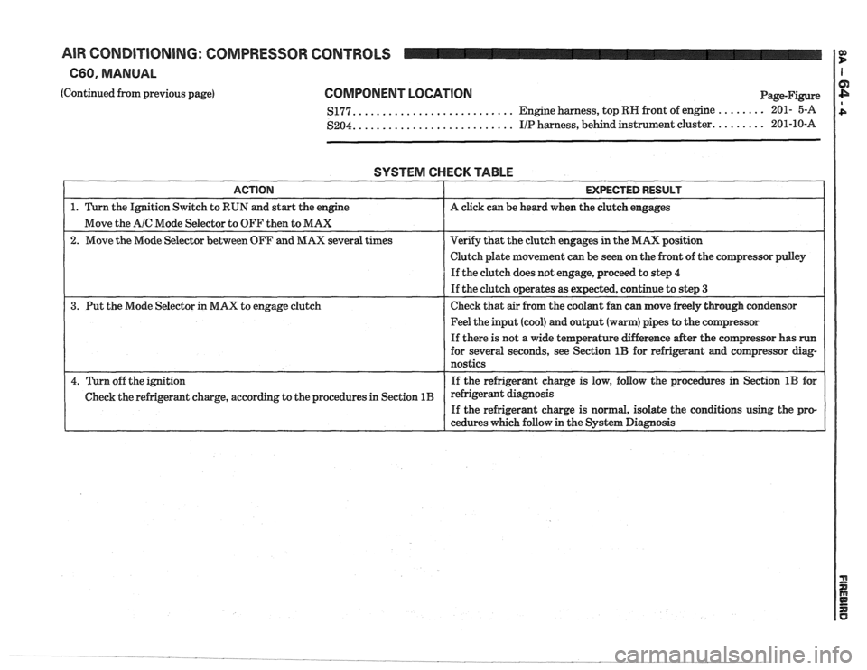
(Continued from previous page) COMPONENT LOCATION
.......................... $177. Engine harness,
top RN front of engine ........ 201- 5-A
.......................... $204. I/P harness, behind instrument cluster. ........ 201-10-A
SYSTEM CHECK TABLE
I ACTION I EXPECTED RESULT I
1. Turn the Ignition Switch to RUN and start the engine A click can be heard when the clutch engages
Move the
A/C Mode Selector to OFF then to MAX
2. Move the Mode Selector between OFF and MAX several times Verify
that the clutch engages in the MAX position
I I Clutch plate movement can be seen on the front of the comgressor pdey I
I I If the clutch does not engage, proceed to step 4
If the clutch operates as expected, continue to step
3
3.
Put the Mode Selector in MAX to engage clutch Check
that air from the coolant fan can move freely through condensor
1 1 Feel the input (cool) and output (warm) pipes to the cornpressor I
I
If there is not a wide temperature difference after the compressor has run
for several seconds, see Section 1B for refrigerant and compressor diag-
nostics
4. Turn off the ignition If the
refrigerant charge is low, follow the procedures in Section 1B for
Check the refrigerant charge, according to the procedures in Section
1B refrigerant diagnosis
If the refrigerant charge is normal, isolate the conations using the pro-
cedures which follow in the System Diagnosis
Page 1360 of 1825
AIR CONDITIONING: COMPRESSOR CONTROLS I i
660, MANUAL B
2
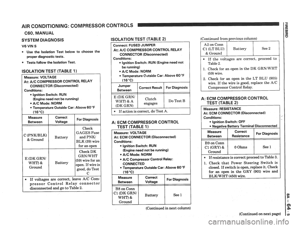
SYSTEM DlAGNOSlS
V6 VIN S
0 Use the Isolation Test below to choose the
proper diagnostic tests.
0 Tests follow the Isolation Test.
ISOLATION TEST (TABLE 1)
At: AIC COMPRESSOR CONTROL RELAY
CONNECTOR (Disconnected)
0 lgnition Switch: RUN
(Engine need not be running)
0 AIC Mode: NORM
0 Temperature Outside Car: Above 60 OF
Measure
Between Correct I For Diagnosis / Voltage
I
I - I
Check
C
(PNKIBLK) GAGES Fuse
BLK
(39) wire
for
an open
Check DK
I 0 If voltages are correct, leave AIC Corn-]
I I
E (DK GRNl
WNT) &
Ground
I
.#
pressor Control Relay connector
disconnected and go to Table
2.
ISOLATION TEST (TAB!-E 2) u (Continued -from previous column) I I I I I
Battery
Connect: FUSED JUMPER
At:
AlC COMPRESSOR CONTROL RELAY
CONNECTOR (Disconnected)
Conditions:
lgnition Switch: RUN (Engine need not
GRNIWNT
(59) wire for an
open. ~f wire is
good, do Test
C
be running)
0 AIC Mode: NORM
0 Temperature Ot~tside Car: Above 60°F
Correct Result For Diagnosis
1 ::zn 1 1 1
If action is correct, do Test A.
E (DK GRNI
WHT' & A
(DK GRN)
A: ECM COMPRESSOR CONTROL
TEST (TABLE
1)
Measure: VOLTAGE
At: ECM CONNECTOR (Disconnected)
Conditions:
0 lgnition Switch: RUN
(Engine need not be running)
AIC Mode: NORM
0 AIC Compressor Control Relay:
CONNECTED
Temperature Outside Car: Above 60°F
116°C)
Clutch
engages
[ B8 on Conn 1 I I
Do Test B
Measure
Between
I C1g,";,"N1 I Battery I See 1 I
I Ground I
(Continued in next column)
Correct
Voltage
1 ~~~~~~) 1 Battery 1 See 2
& Ground
If the voltages are correct, proceed
to
Table 2.
For Diagnosis
1. Check for an open in the DK GRNlWNT
(59) wire.
2. Check for an open in the LT BLU (905)
wire. If the wire
is good, replace the AlC
Com~rc!ssor Control Relay.
A: ECM COMPRESSOR CONTROL
TEST ('FABLE
2)
Measure: RESISTANCE
At: ECM CONNECTOR (Disconnected)
Conditions:
0 lgnition Switch: OFF
Negative Battery Terminal
I Disconnected
Measure I Correct I For Diagnosis I I Between Resistance
B9 on
Conn
C1 (GRY) & 0 Ohms See 1
Ground
0 If
resistance is correct proceed to Table 3.
1. Check that Power Steering Switch is
closed.
If switch is open, replace it. Check
for
an open in the GRY (901) wire and
(Continued on next page)
Page 1361 of 1825
AIR CONDITIONING: COMPRESSOR CONTROLS
C60, MANUAL
(Continued from previous page)
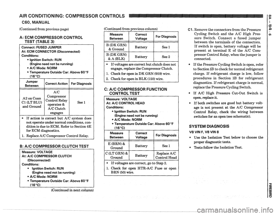
A: ECM COMPRESSOR CONTROL
TEST (TABLE
3)
Connect: FUSED JUMPER
At: ECM CONNECTOR (Disconnected)
Conditions:
0 Ignition Switch: RUN
(Engine need not be running]
AIC Mode: NORM
Temperature Outside Car: Above 60 OF
(16°C)
Jumper
Correct Action For Diagnosis
Between
engages
r If action is correct but A/C system does
not operate under normal conditions, con-
dition
is due to ECM. Refer to Section 6E
for ECM diagnostics.
1. Replace AIC Compressor Control Relay.
Corm
ILT BLU'
and Ground
B: AIC COMPRESSOR CLUTCH TEST
Measure: VOLTAGE
At:
AIC COMPRESSOR CLUTCH
(Disconnected)
Conditions: Ignition Switch: RUN
(Engine need not
be running)
r Ale Mode: NORM
Temperature Outside Car: Above
60 OF
116OC)
Compressor
Control Relay
operates
&
AIC Clutch (Continued from previous column)
1
See 1
Measure
I Between Correct I For
Diagnosis I I Vdtaas
/ (DK GRN' I Battery I See 1 & Ground
I BLz,",":' ( Battery I See 2
If voltages are correct hut clutch does not
engage, replace the Compressor Clutch.
I 1. Check for open in DK GRN (959) wire. 1
2. Check for open in BLK (150) wire.
C: AIC COMPRESSOR FUNCTION
CONTROL TEST
lgnition Switch: RUN
(Engine need not be running)
A/C Mode: NORM
open NTR-AIC Fuse or open
61. Remove the connectors from the Pressure
Cycling Switch and the
A/C High Pres-
sure Switch. Connect a fused jumper
between the ter
als of the connectors.
If switch is open, battery voltage will be
present at terminal
E of the AlC Com-
pressor Control Relay, when the jumper is
connected.
0 If the Pressure Cycling Switch is open, refer
to Section
1B to check for normal refrigerant
charge. If refrigerant charge is low, follow
procedures in Section
1B for refrigerant
diagnostics.
If refrigerant charge is normal,
replace the Pressure Cycling Switch.
@ If A/C High Pressure Cut-Out Switch is
open, replace it.
0 If both switches are good but battery volt-
age is not present at the
AIC Compressor
Control Relay, check the wiring between
switches for
an open (see schematic).
SYSTEM DIAGNOSIS
V8 VlN F, V8 VIN 8
@ Use the Isolation Test below to choose the
proper diagnostic tests.
Tests follow the Isolation Test.
(Continued in next co
Page 1362 of 1825
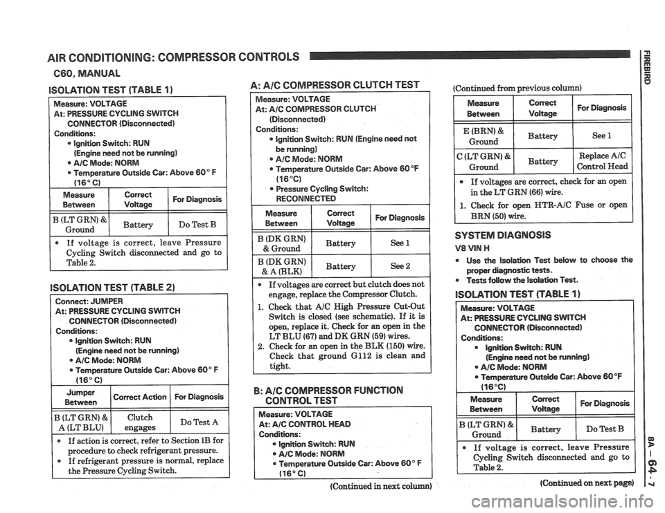
AIR CONDITIONING: COMPRESSOR
660, MANUAL
ISOLATION TEST (TABLE 1)
Measure: VOLTAGE
At: PRESSURE CYCLING
SWITCH
CONNECTOR (Disconnected)
Conditions: lgnition Switch: RUN
(Engine need not be running)
0 AIC Mode: NORM
Temperantre Outside Car: Above 60" F
(16" C)
Measure
Between Correct For Diagnosis /
I ILT Ground GRN'8rl Battery I Do Test B I
. If voltage is correct, leave Pressure
Cycling Switch disconnected and go to
Table
2.
ISOLATION TEST (TABLE 2)
Connect: JUMPER
At: PRESSURE CYCLING SWITCH
CONNECTOR (Disconnected)
Conditions: lgnition Switch: RUN
(Engine need not be running)
@ AIC Mode: NORM
0 Temperature Outside Car: Above 60" F
(16" C) I
Jumper I Correct Ac~on 1 For Diagnosis I I Between
If action is correct, refer to Section 1B for I
B (LT GRN) &
A (LT BLU)
I procedure to check refrigerant pressure. I
If refrigerant pressure is normal, replace
the Pressure Cycling Switch.
Clutch
engages
CONTROLS
Do Test A
A: Pale COMPRESSOR CLUTCH TEST
Measure: VOLTAGE
At:
A/C COMPRESSOR CLUTCH
(Disconnected)
Conditions:
0 Ignition Switch: RUN (Engine need not
be running)
0 AIC Mode: NORM
Temperature Outside Car: Above 60
OF
(16°C)
. Pressure Cycling Switch:
RECONNECTED
I
I ':"A':,",":' 1 ~attery I See 2 I
If voltages are correct but clutch does not
engage, replace the Compressor Clutch.
1. Check that AIC High Pressure Cut-Out
Switch is closed (see schematic). If
it is
open, replace it. Check for
an open in the
LT BLU
(67) and DK GRN (59) wires.
2. Check for an open in the BLK (150) wire.
Check that ground 6112 is clean and
tight.
B: AIC COMPRESSOR FUNCTION
CONTROL TEST
Measure: VOLTAGE
At: AIC CONTROL HEAD
Conditions: lgnition Switch: RUN
A/C Mode: NORM
0 Temperature Outside Car: Above 60" F
(16" C)
(Continued in next colum)
(Continued from previous column)
Measure Correct For Diagnosis
Between Voltage
Battery 1 See 1
Replace Ale
Control Head
If voltages are correct, check for an open
in the LT GRN
(66) wire.
1. Check for open HTR-AIC Fuse or open
BRN (50) wire.
SYSTEM DlAGlUOSlS
V8 VlN H
0 Use the isolation Test below to choose the
proper diagnostic tests.
Tests follow the Isolation Test.
lSOLATlOlU TEST (TABLE 1)
At: PRESSURE CYCLING SWITCH
CONNECTOR (Disconnected)
Ignition Switch: RUN
(Engine need not be running)
. A/C Mode: NORM
ramre Outside Car: Above 60 OF
Measure
I Between Correct I For Diagnosis I
Battery I Do Test B I I I
. If voltage is correct, leave Pressure
1 Cycling switch disconnected and go to I
(Continued on next page)
Page 1363 of 1825
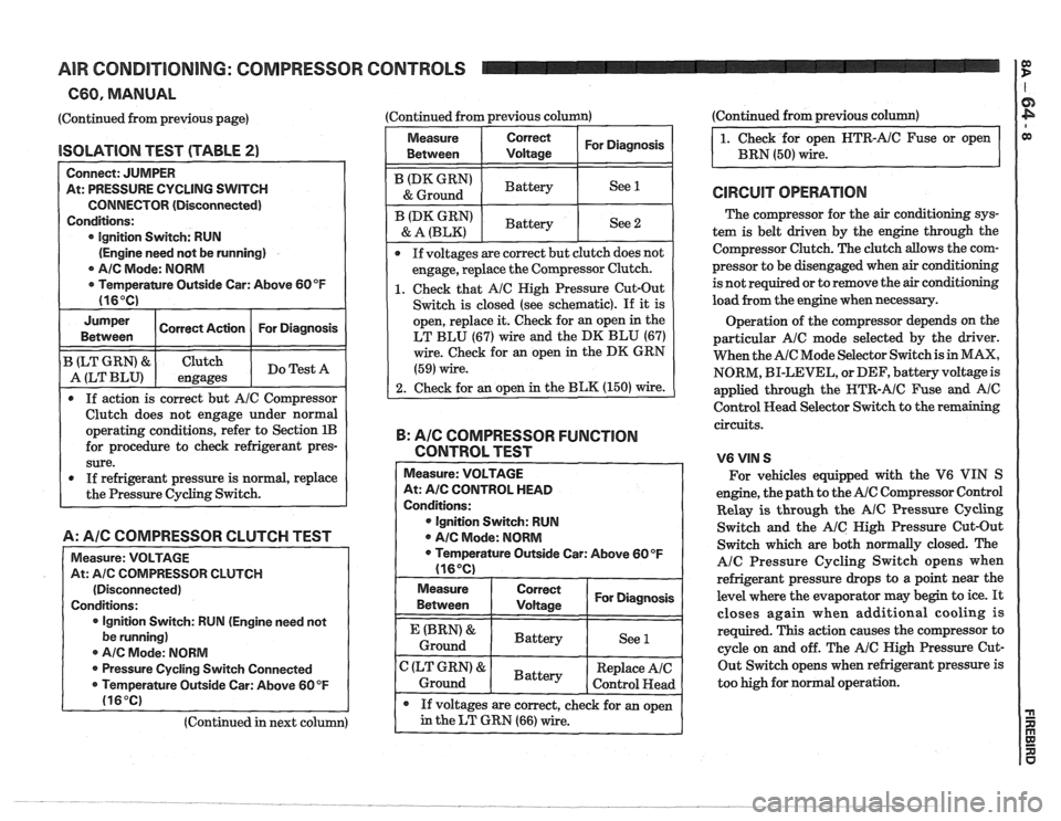
AIR CONDITIONING: COMPRESSOR CONTROLS
C60, MANUAL
(Continued from previous page)
lSOLATlON TEST (TABLE 2)
Connect: JUMPER
At: PRESSURE CYCLING SWITCH
CONNECTOR (Disconnected)
Conditions:
lgnition Switch: RUN
(Engine need not be running)
0 AIC Mode: NORM
r Temperamre Outside Car: Above 60°F
Jumper I Correct Action I For Diagnosis I Between
B (LT GRN) & Clutch
A (LT BLU) engages Do
Test A
0 If action is correct but AIC Compressor
Clutch does not engage under normal
operating conditions, refer to Section
1B
for procedure to check refrigerant pres-
sure.
0 If refrigerant pressure is normal, replace
the Pressure Cycling Switch.
A: A/C COMPRESSOR CLUTCH TEST
Measure: VOLTAGE
At:
Ale COlVlPRESSOR CLUTCH
(Disconnected)
Conditions:
lgnition Switch:
RUN (Engine need not
be running)
0 A/C Mode: NORM
@ Pressure Cycling Switch Connected
0 Temperature Outside Car: Above 60 OF
(16°C)
(Continued in next column) (Continued
from previous column) (Continued
from previous column)
Measure
Between Correct I For Diagnosis I 1. Check for open HTR-AIC Fuse or open
BRN
(50) wire.
I (DK GRN' I Battery I See 1 I & Ground
@ If voltages are correct but clutch does not
engage, replace the Compressor Clutch.
1. Check that Ale Nigh Pressure Cut-Out
Switch is closed (see schematic).
If it is
open, replace it. Check for an open in the
LT BLU (67) wire and the DK BLU (67)
wire. Check for an open in the DK GRN
(59) wire.
2. Check for an open in the BLK (150) wire.
ID* GRN)
& A (BLK)
B: AIG COMPRESSOR FUNCTION
CONTROL TEST - -
Measure: VOLTAGE
At:
A/C CONTROL HEAD
Conditions:
@ Ignition Switch: RUN
@ AIC Mode: NORM
0 Temperature Outside Car: Above 60OF
(16OC)
Battery
Measure
Between
I ~~~~~~ I For Diagnosis I
See 2
(BRN' &
Ground
If voltages are correct, check for an open
in the LT GRN (66) wire.
C (LT GRN) &
Ground The
compressor for the
air conditioning sys-
tem is belt driven by the engine through the
Compressor Clutch. The clutch allows the com-
pressor to be disengaged when
air conditioning
is not required or to remove the
air conditioning
load from the engine when necessary.
-
Battery Operation
of the compressor depends on the
particular
AIC mode selected by the driver.
When the
AIC Mode Selector Switch is in MAX,
NORM, BI-LEVEL, or DEF, battery voltage is
applied through the
HTR-AIC Fuse and Ale
Control Head Selector Switch to the remaining
circuits.
See
1
Battery
V6VIN S
For vehicles equipped with the V6 VIN S
engine, the path to the
AIC Compressor Control
Relay
is through the AIC Pressure Cycling
Switch and the
AIC Nigh Pressure Cut-Out
Switch which are both normally closed. The
AlC Pressure Cycling Switch opens when
refrigerant pressure drops to a point near the
level where the evaporator may begin to ice.
It
closes again when additional cooling is
required. This action causes the compressor to
cycle on and off. The
AIC High Pressure Cut-
Out Switch opens when refrigerant pressure is
too high for normal operation.
Replace AIC
Control
Head
Page 1366 of 1825
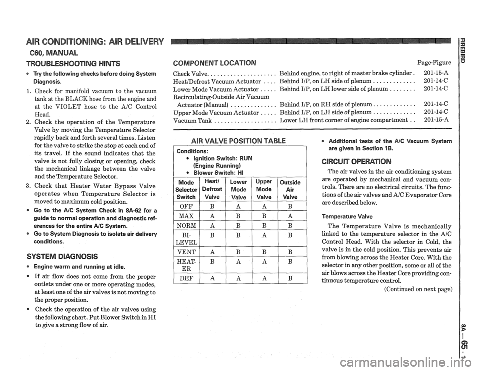
AIR CONDITIONING: AlR DELIVERY
660, MANUAL
TROUBLESHOOTING HINTS
Try the following checks before doing System
Diagnosis.
1. Cheek for manifold vacuum to the vacuum
tank at the BLACK hose from the engine and
at the VIOLET hose to the
A/C Control
Head.
2. Check the operation of the Temperature
Valve by moving the Temperature Selector
rapidly back and forth several times. Listen
for the valve to strike the stop at each end of
its travel.
If the sound indicates that the
valve is not fully closing or opening, check
the mechanical linkage between the valve
and the Temperature Selector.
3. Check that Heater Water Bypass Valve
operates when Temperature Selector is
moved to maximum cold position.
Go to the AlC System Check in 8A-62 for a
guide to normal operation and diagnostic ref-
erences for the entire
AIC System.
r Go to Systern Diagnosis to isolate air delivery
conditions.
SYSTEM DIAGNOSIS
Engine vvarm and running at idle.
If air flow does not come from the proper
outlets under one or more operating modes,
at least one of the air valves is not moving to
the proper position.
Check the operation of the air valves using
the following chart. Put Blower Switch in
HI
to give a strong flow of air.
COMPONENT LOGATlORl Page-Figure
Check Valve.
. . . . . . . . . . . . . . . . . . . . Behind engine, to right of master brake cylinder . 201-15-A
HeatIDefrost Vacuum Actuator . . . . Behind IIP, on LN side of plenum . . . . . . . . . . . . . 201-14-6
Lower Mode Vacuum Actuator
. . . . . Behind I/P, on LH lower side of plenum . . . . . . . . 201-14-C
Recirculating-Outside Air Vacuurn
Actuator (Manual) . . . . . . . . . . . . . . Behind IIP, on RH side of plenum. . . . . . . . . . . . . 201-14-6
Upper Mode Vacuum Actuator
. . . . . Behind I/P, on LN side of plenum . . . . . . . . . . . . . 201-14-6
Vacuum Tank
. . . . . . . . . . . . . . . . . . . Lower LIH front corner of engine compartment . . 201-15-A
AIR VALVE POSlTlON TABLE * Additional tests of the Ale Vacuum System
are given in Section
1 B.
GIWCUiT OPEMTIOIU
The air valves in the air conditioning system
are operated by mechanical and vacuum con-
trols. There are no electrical circuits. The func-
tions of the air valves and
A/C Evaporator Core
are described below.
Temperature Valve
The Temperature Valve is mechanically
linked to the temperature selector in the
AIC
Control Head. With the selector in Cold, the
valve is in the cold position. This prevents air
from blowing across the Heater Core. With the
selector in any other position, some or
all of the
air blows across the Heater Core providing con-
tinuous temperature control.
(Continued on next page)
Page 1371 of 1825
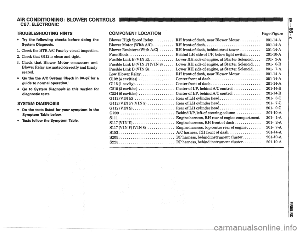
AIR CONDITIONING: BLOWER CONTROLS
TROUBLESHOOTING NlNTS
a Try the following checks before doing the
System Diagnosis
.
1 . Check the HTR A/C Fuse by visual inspection .
2 . Check that 6112 is clean and tight .
3 . Check that Blower Motor connectors and
Blower Relay are mated correctly and firmly
seated
.
a Go the the AIC Systern Check in 813-62 for a
guide to normal operation
.
Go to Systern Diagnosis in this section for
diagnostic tests
.
SYSTEM DIAGNOSIS
Do the tests listed for your symptom in the
Symptom Table below
.
Tests follow the Symptom Table .
COMPONENT LOCATION Page-Figure
Blower High Speed Relay
.......... RH front of dash. near Blower Motor ..........
Blower Motor (With AIC) .......... RH front of dash ...........................
Blower Resistors (With AIC) ....... RH front of dash. behind strut tower ..........
...................... Fuse Block
Behind LH side of IIP. below light switch .......
............ Fusible Link B (VIN E) Lower RH side of engine. at Starter Solenoid ....
Fusible Link B (VIN F) (VIN 8) ..... Lower RH side of engine. at Starter Solenoid ....
............ Fusible Link B (VIN S) Lower RN side of engine. at Starter Solenoid ....
................ Low Blower Relay RH front of dash. near Blower Motor ..........
........................ ................. C102 (4 cavities) Center
front of dash
................... ........................ C115 (1 cavity) Center
front of dash
................. ............. C215 (3 cavities) Center
of IIP. behind AlC control
................. ............. 6224 (6 cavities) Center
of IIP. behind Ale control
................... .................... 6112 (VIN E) Rear of LH cylinder head
............. .................... 6112 (VIN F) (VIN 8) Rear of LH cylinder head
.................... .................... 6112 (VIN S) Rear
of LN cylinder head
.......................... ............ 6200 Behind I/P. left of steering column
........................... Slll Engine harness. RN rear of engine compartment
.................... ............. S117 (VIN E) Engine harness. RH front of dash
............. ....... S117 (VIN F) (VIN 8) Engine harness. top center rear of engine
........................... ................ S153 AIC harness. RH front of dash
........................... ......... S205 IIP harness. behind instrument cluster
........................... S225 IIP harness. behind instrument cluster .........