1988 PONTIAC FIERO wheel size
[x] Cancel search: wheel sizePage 348 of 1825
ENGINE GENERAL INFORMATION 6-3
B, Section 6E2 - Fuel Injection (TBI)
B, Section 6E3 - Fuel Injection (Ported)
ENGINE MECHANICAL DIAGNOSIS
The following diagnostic information covers common problems and possible causes. When
the proper diagnosis is made, the problem should be corrected by adjustment, repair or part
replacement as required. Refer to the appropriate section of the manual for these procedures.
EXCESSIVE OIL LOSS
B, External oil leaks. Tighten bolts and/or replace o Continuous high speed driving, and/or severe
gaskets and seals as necessary. usage
such as trailer hauling, will normally cause
decreased oil mileage.
e Improper reading of dipstick. Check oil with car PCV system malfunctioning. on a level surface and allow adequate drain-down Valve guides and/or valve stem seals worn, or time.
seals omitted. Ream guides and install oversize
service valves and/or new valve stem seals.
Improper Use S.A'E' Piston rings broken, worn, or not seateded. Allow viscosity for prevailing temperatures. See
adequate time for rings to seat. Replace broken
Owner's Manual for proper specifications.
or worn rings, as necessary.
Piston improperly installed or misfitted.
LOW OIL PRESSURE
Slow idle speed. Set idle speed to correct
specification, if not ECM controlled.
Incorrect, or malfunctioning, oil pressure switch.
Incorrect, or malfunctioning, oil pressure gage.
Replace with proper gage.
.*
Improper oil viscosity, or diluted oil. install oil of
proper viscosity for expected temperature, or
install new oil if diluted with moisture or
unburned fuel mixtures.
o Oil pump worn or dirty.
e Plugged oil filter.
e Oil pickup screen loose or plugged.
B, Hole in oil pickup tube.
e Excessive bearing clearance. Replace if necessary.
o Cracked, porous or plugged oil galleys. Repair or
replace block.
o Galley plugs missing or misinstalled. Install
plugs, or repair as necessary.
VALVE TRAIN NOISE
e Low oil pressure. Repair as necessary. (See o Broken valve spring.
preceding diagnosis for low oil pressure.)
o Sticking valves.
o Loose rocker arm attachments. Inspect and B, Lifters worn, dirty, or defective. Clean, inspect,
test and replace as necessary.
repair as necessary.
o Camshaft worn, or poor machining. Replace
o Worn rocker arm and/or pushrod. camshaft.
B, Worn valve guides.
ENGINE KNOCK DIAGNOSIS
KNOCKS COLD AND CONTINUES FOR TWO TO THREE MINUTES
INCREASES
WITH TORQUE
o Vacuum operated EFE engines may have valve o Excessive piston to bore clearance. Replace
knock. Replace EFE valve. piston.
e Flywheel contacting splash shield. Reposition
splash shield.
e Loose or broken balancer or drive pulleys.
Tighten, or replace as necessary. Cold engine piston knock usually
disappears when the cylinder is grounded
out. Cold engine piston knock which
disappears in 1.5 minutes should be
considered acceptable.
Page 349 of 1825
6-4 ENGINE GENERAL INFORMATION
Bent connecting rod.
HEAVY KNOCK H0"FVVI"F TORQUE APPLIED
Broken balancer, or pulley hub. Replace parts as e Exhaust system grounded. Reposition as
necessary. necessary.
Loose torque converter bolts. Flywheel
cracked.
e Excessive main bearing clearance. Replace as
Accessory belts too tight or nicked. Replace
necessary.
and/or tension to specs as necessary.
e Excessive rod bearing clearance. Replace as
necessary.
LIGHT KNOCK HOT
Detonation or spark knock. Check operation of e Loose torque converter bolts.
EST or ESC (See Section
6D or 6E). Check e Exhaust leak at manifold. Tighten bolts and/or
engine timing and fuel quality.
replace gasket.
8 Excessive rod bearing clearance. Replace
bearings as necessary.
KNOCKS ON INITIAL START-UP BUT ONLY LASTS A FEW SECONDS
Noisy mechanical fuel pump. Replace pump.
When the engine is stopped, some valves
will be open. Spring pressure against lifters
Improper oil viscosity. Install proper oil viscosity will
tend to bleed lifter down. Attempts to
for expected temperatures. See Owner's Manual. repair
should be made only if the problem
is consistent.
Hydraulic lifter bleed down. Clean, test and @ Excessive crankshaft end clearance. Replace
replace as necessary. crankshaft
thrust bearing.
@ Excessive front main bearing clearance. Replace
worn parts.
KNOCKS AT IDLE HOT
Loose or worn drive belts. Tension and/or @ Excessive piston pin clearance. Ream and install
replace as necessary. oversize pins. (VIN R and 2) or replace piston
A/C Compressor or generator bearing. Replace and
pin.
as necessary.
e Connecting rod alignment. Check and replace
rods as necessary.
Noisy mechanical fuel pump. Replace pump.
8 Insufficient piston to bore clearance. Hone bore
Valve train. Replace parts as necessary. and
fit new piston.
@ Loose crankshaft balancer. Torque and/or
Improper oil viscosity. Install proper viscosity oil
replace worn parts.
for expected temperature4 See Owner" e Piston pin offset to wrong side. Install correct
ENGINE OVERHEATS
Coolant system leak, oil cooler system leak, or
2. Belt slipping or damaged. Replace tensioner, or
coolant recovery system not operating. Check for belt, as required.
leaks and correct as required. Check coolant
3. Thermostat stuck closed. Check and replace if
recovery tank, hose and radiator cap.
required.
4. Electrical cooling fan operation. See the
ELECTRICAL TROUBLESHOOTING
MANUAL.
5. Head gasket leaking. Check and repair as
required.
Page 364 of 1825
2.8 LITER V.6 6A2.13
Torque bolts as shown in Figure 6A2-15.
4. Install
push rods and loosely retain with rocker
arms. Make sure lower ends of
pushrods are in
lifter seats.
5. Install intake manifold.
6. Raise vehicle.
7. Install dipstick tube bracket.
8. Connect exhaust pipe
to exhaust manifold flange.
9. Lower vehicle.
10. Adjust
valve lash as previously outlined.
11. Continue
following intake manifold installation
for build up.
Removal (Right)
Remove intake manifold as previously outlined.
Raise vehicle.
Disconnect exhaust pipe.
Drain engine block.
Lower vehicle.
Loosen rocker arms until able to remove push
rod.
Remove serpentine belt.
Remove tensioner.
Remove A.I.R. bracket.
Remove generator bracket.
Remove head bolts.
Remove head.
Installation (Right)
The gasket surfaces on both the head and cylinder
case
deck must be clean of any foreign matter and free
of nicks of heavy scratches. Cylinder bolt threads in the
case and threads on the cylinder head bolts must be
clean. Dirt will affect bolt torque.
1. Place the gasket in position, over the dowel pins,
with the note "This Side Up" showing.
2. Install cylinder head.
3. Coat cylinder head bolt threads with sealer,
#lo52080 or equivalent, and install bolts.
Torque bolts as shown in (Figure
6A2-15).
Install push rods and loosely retain with rocker
arms. Make sure lower ends of push rods are in
lifter seats.
Install intake manifold.
Raise vehicle.
Install exhaust pipe to exhaust manifold flange.
Lower vehicle.
Adjust valve lash as previously outlined.
Install AIR bracket.
Install tensioner.
Install generator bracket.
Continue following intake manifold installation
for build up.
Disassembly
1. With cylinder head removed, remove rocker arm
nuts, balls and rocker arms (if not previously
done).
2. Using tool J-8062, compress the valve springs and
remove valve keys. Release the compressor tool and
remove spring caps, oil shedders, springs and
damper assemblies, then remove oil seals.
3. Remove valves from cylinder head and place
them in a rack so they can be installed in their
original positions.
Cleaning and Inspection
Clean all carbon from combustion chambers and
valve ports using 'tool
5-8089.
Thoroughly clean valve guides using 5-8 10 1.
Clean all carbon and sludge from push rods,
rocker arms and push rod guides.
Clean valve stems and heads on a buffing wheel.
Clean carbon deposits from head gasket mating
surface.
Inspect cylinder head for cracks in the exhaust
ports, combustion chambers, or external cracks
to the water jacket.
Inspect the valves for burned heads, cracked faces
or damaged stems.
NOTICE: Excessive valve stem to bore clearance
will cause high oil consumption and may cause
valve breakage. Insufficient clearance will result in
noise and sticky functioning of the valve and
disturb engine smoothness.
8. Measure valve stem clearance as follows:
a. Clamp
a dial indicator on one side of the
cylinder head. Locate the indicator so that
movement of the valve stem from side to
side (crosswise to the head) will cause direct
movement of the indicator stem. The
indicator stem must contact the side of the
valve stem just above the guide.
b. Drop
the valve head
1.5mm off the valve
seat.
c. Move
the stem of the valve from side to side,
using light pressure, to obtain a clearance
reading. If clearance exceeds specifications,
it will be necessary to ream valve guides for
oversize valves. Service valves are available
in std., 089,
.394 and .775mm O.S. sizes.
9. Check
valve spring tension with tool J-8056,
spring tester. Springs should be compressed to the
specified height and checked against the
specifications chart. Springs should be replaced if
not within 44
N (10 Ibs.) of the specified load
(without dampers).
10. Inspect
rocker arm studs for wear or damage.
ROCKER ARM STUDS
Cylinder heads use threaded rocker arm studs.
Rocker arm studs that have damaged threads should
be replaced with new studs. If, for some reason, the
threads in the head
are damaged or stripped, the head
can be retapped, and a helical type insert added. If such
an insert is not available, the head should be replaced.
VALVE GUIDES
Valves with oversize stems are available in .089,
,394 and ,775mm over sizes. To ream the valve guide
Page 376 of 1825
2.8 LITER V-6 6A2-25
Fitting
1. Select rings comparable in size to the piston being
used.
2. Slip
the compression ring in the cylinder bore;
then press the ring down into the cylinder bore
about 6mm above ring travel. Be sure ring is
square with cylinder wall.
3. Measure the space or gap between the ends of the
ring with a feeler gage (Figure
6A2-33).
4. If
the gap between the ends of the ring is below
specifications, remove the ring and try another
for fit.
5. Fit each compression ring to the cylinder in
which it is going to be used.
6. If the pistons have not been cleaned and inspected
as previously outlined, do so.
7. Slip the outer surface of the top and second
compression ring into the respective piston ring
groove and roll the ring entirely around the
groove (Figure
6A2-34). If binding occurs at any
point, the cause should be determined. If there is
a ring groove, remove by dressing with a fine cut
file. If the binding is caused by a distorted ring,
check a new ring.
Installation
1. Install oil ring spacer in groove being sure ends
are butted and not overlapped.
2. Hold
spacer ends butted and install lower steel oil
ring rail.
3. Install upper
steel oil ring rail with gap staggered.
4. Flex
the oil ring assembly to make sure ring is
free. If binding occurs, the cause should be
detemined. If caused by ring groove, remove by
dressing groove with a fine cut file. If binding is
caused by a distorted ring, check a new ring.
5. Install second compression ring. Stagger gap
from other rings.
6. Install top compression ring with gap properly
located.
ENGINE ASSEMBLY
Removal
Disconnect battery.
Remove air cleaner.
Remove hood. Drain radiator.
Remove lower radiator hose.
Remove upper fan shroud.
Remove upper radiator hose and coolant
recovery hose.
Remove transmission cooler lines. Remove radiator.
Remove fan assembly.
Remove heater hoses.
Disconnect carburetor linkage, includes cruise
control detent cable.
Remove vacuum brake booster line.
Remove distributor cap and lay wiring aside.
Disconnect necessary wires and hoses.
Remove power steering pump and lay aside. Raise
vehicle.
Remove exhaust pipes at exhaust manifold.
Remove dust cover.
Remove converter bolts.
Disconnect starter wires.
Remove bell housing bolts.
Remove motor mount through bolts.
Disconnect fuel lines at fuel pump.
Lower vehicle. Support transmission.
Remove
A.I.R./Converter pipes bracket.
Remove engine, include removing wire from
bracket at rear left of engine.
Installation
Position engine assembly in vehicle.
Attach motor mount to engine brackets and
lower engine in place.
Remove engine lifting device.
Remove transmission floor jack.
Raise vehicle on hoist.
Install mount "through" bolts. Torque to
specifications.
Install bell housing bolts. Torque to
specifications.
On vehicles with automatic transmission, install
converter to flywheel attaching bolts. Torque to
specifications.
Install flywheel splash shield of conveter housing
cover as applicable. Torque attaching bolts to
specifications.
Install starter wires.
Connect fuel lines.
Connect exhaust pipe at manifold.
Lower vehicle on hoist.
Reinstall power steering pump, if so equipped.
Connect necessary wires and hoses.
Install radiator and fan shroud and reconnect
radiator and heater hoses.
Fill cooling system.
Fill crankcase with oil. See owner's manual for
specifications.
Install air cleaner.
Install hood.
Connect battery cables.
NOTICE: To avoid possible arcing of battery,
connect positive battery cable first.
22. Start engine, check for leaks and check timing.
CRANKSHAFT
The crankshaft can be removed while the engine
is dissasembled for overhaul, as previously outlined or
without complete disassembly.
Removal
1. With the engine removed from the vehicle,
remove the clutch assembly (if equipped) and
flywheel. Mount engine in stand and clamp
securely.
Page 377 of 1825
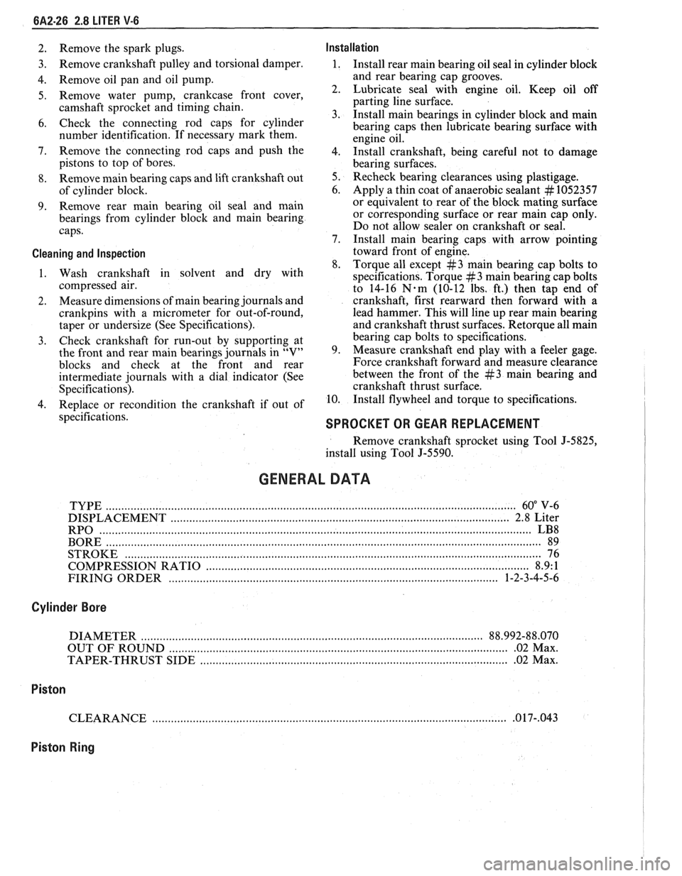
6A2-26 2.8 LITER V-6
2. Remove the spark plugs. Installation
3. Remove
crankshaft pulley and torsional damper. 1. Install rear main bearing oil seal in cylinder block
4. Remove oil pan and oil pump. and
rear bearing cap grooves.
5. Remove water pump, crankcase front cover, 2. Lubricate seal with engine oil. Keep oil off
camshaft sprocket and timing chain. parting
line surface.
3. Install main bearings in cylinder block and main
6. Check the connecting rod caps for cylinder
bearing caps then lubricate bearing surface with
number identification. If necessary mark them.
engine oil.
7. Remove the connecting rod caps and
push the
4. 1n;tall crankshaft, being careful not to damage
pistons to top of bores.
bearing surfaces.
8. Remove main bearing caps and lift crankshaft out 5. Recheck bearing clearances using plastigage.
of cylinder block. 6.
Apply a thin coat of anaerobic sealant
# 1052357
9. Remove rear
main bearing oil seal and main or
equivalent to rear of the block mating surface
bearings from cylinder block and main bearing or corresponding
surface or rear main cap only.
caps. Do
not allow sealer on crankshaft or seal.
7. Install main bearing caps with arrow pointing
Cleaning and Inspection toward front of engine.
8. Torque all except
#3 main bearing cap bolts to
1. Wash crankshaft in solvent and dry with
specifications. Torque
#3 main bearing cap bolts
compressed air. to 14-16
N-m (10-12 lbs. ft.) then tap end of
2. Measure
dimensions of main bearing journals and crankshaft, first rearward then forward with a
crankpins with a micrometer for out-of-round, lead
hammer. This will line up rear main bearing
taper or undersize (See Specifications). and crankshaft
thrust surfaces.
Retorque all main
3. Check
crankshaft for run-out by supporting at bearing
cap bolts to specifications.
the front and rear main bearings journals in "V" 9. Measure crankshaft
end play with a feeler gage.
blocks and check at the front and rear Force crankshaft forward and measure clearance
intermediate journals with a dial indicator (See between the front of the
#3 main bearing and
Specifications). crankshaft thrust surface.
4. Replace or recondition the crankshaft if out of 10.
Install flywheel and torque to specifications.
specifications.
SPROCKET OR GEAR REPLACEMENT
Remove crankshaft sprocket using Tool J-5825,
install using Tool J-5590.
GENERAL DATA
TYPE .................................................................................................................................... 60" V-6
DISPLACEMENT
............................................................................................................. 2.8 Liter
RPO
........................................................................................................................................... LB8
BORE ......................................................................................................................................... 89
STROKE
................................... .... ............................................................................................... 76
COMPRESSION RATIO
....................................................................................................... 8.9: 1
FIRING ORDER
.......................................................................................................... 1-2-3-4-5-6
Cylinder Bore
DIAMETER .............................................................................................................. 88.992-88.070
OUT OF ROUND
............................................................................................................. .02 Max.
TAPER-THRUST SIDE
................................................................................................. .02 Max.
Piston
CLEARANCE .................................................................................................................. .O 17-,043
Piston Ring
Page 406 of 1825
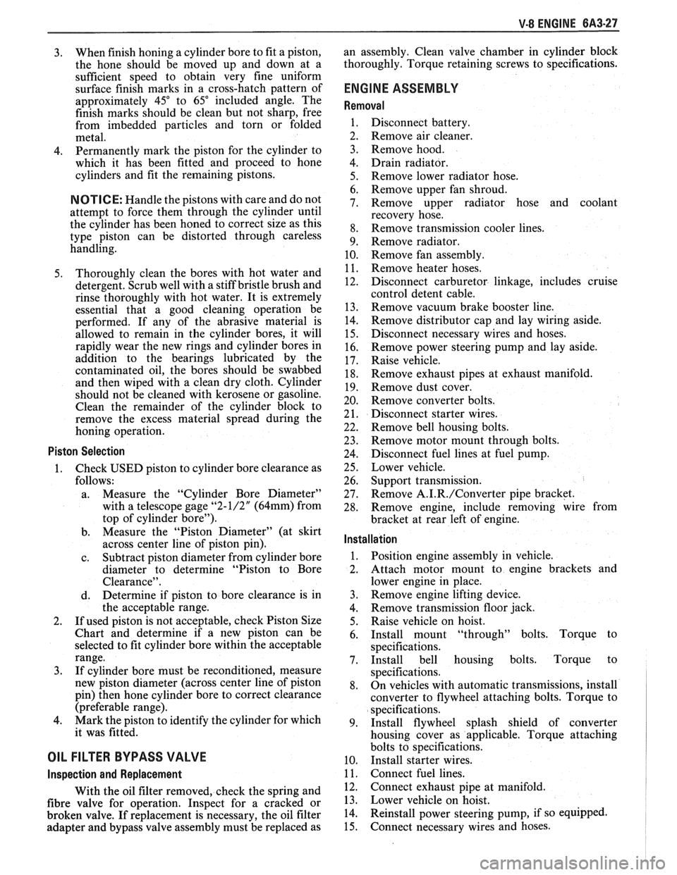
V-8 ENGINE 6A3-27
3. When finish honing
a cylinder bore to fit a piston,
the hone should be moved up and down at a
sufficient speed to obtain very fine uniform
surface finish marks in a cross-hatch pattern of
approximately
45" to 65" included angle. The
finish marks should be clean but not sharp, free
from imbedded particles and torn or folded
metal.
4. Permanently mark
the piston for the cylinder to
which it has been fitted and proceed to hone
cylinders and fit the remaining pistons.
NOTICE: Handle the pistons with care and do not
attempt to force them through the cylinder until
the cylinder has been honed to correct size as this
type piston can be distorted through careless
handling.
5. Thoroughly
clean the bores with hot water and
detergent. Scrub well with a stiff bristle brush and
rinse thoroughly with hot water. It is extremely
essential that a good cleaning operation be
performed. If any of the abrasive material is
allowed to remain in the cylinder bores, it will
rapidly wear the new rings and cylinder bores in
addition to the bearings lubricated by the
contaminated oil, the bores should be swabbed
and then wiped with a clean dry cloth. Cylinder
should not be cleaned with kerosene or gasoline.
Clean the remainder of the cylinder block to
remove the excess material spread during the
honing operation.
Piston Selection
1. Check USED piston to cylinder bore clearance as
follows:
a. Measure
the "Cylinder Bore Diameter"
with a telescope gage
"2-1/2" (64mm) from
top of cylinder bore").
b. Measure
the
"Piston Diameter" (at skirt
across center line of piston pin).
c. Subtract
piston diameter from cylinder bore
diameter to determine "Piston to Bore
Clearance".
d. Determine if piston to bore clearance is in
the acceptable range.
2. If
used piston is not acceptable, check Piston Size
Chart and determine if a new piston can be
selected to fit cylinder bore within the acceptable
range.
3. If
cylinder bore must be reconditioned, measure
new piston diameter (across center line of piston
pin) then hone cylinder bore to correct clearance
(preferable range).
4. Mark the piston to identify the cylinder for which
it was fitted.
OIL FILTER BYPASS VALVE
Inspection and Replacement
With the oil filter removed, check the spring and
fibre valve for operation. Inspect for a cracked or
broken valve. If replacement is necessary, the oil filter
adapter and bypass valve assembly must be replaced as an
assembly. Clean valve chamber in cylinder block
thoroughly. Torque retaining screws to specifications.
ENGINE ASSEMBLY
Removal
1. Disconnect battery.
2. Remove air cleaner.
3. Remove hood.
4. Drain radiator.
5. Remove lower radiator hose.
6. Remove upper fan shroud.
7. Remove upper radiator hose and coolant
recovery hose.
8. Remove transmission cooler lines.
9. Remove radiator.
10. Remove fan assembly.
1 1. Remove heater hoses.
12. Disconnect
carburetor linkage, includes cruise
control detent cable.
13. Remove vacuum brake booster line.
14. Remove
distributor cap and lay wiring aside.
15. Disconnect necessary wires and hoses.
16. Remove power steering
pump and lay aside.
17. Raise vehicle.
18. Remove exhaust
pipes at exhaust manifold.
19. Remove dust cover.
20. Remove converter bolts.
2 1. Disconnect starter wires.
22. Remove bell housing bolts.
23. Remove
motor mount through bolts.
24. Disconnect fuel lines
at fuel pump.
25. Lower vehicle.
26. Support transmission.
27. Remove
A.I.R./Converter pipe bracket.
28. Remove engine, include removing wire
from
bracket at rear left of engine.
Installation
1. Position engine
assembly in vehicle.
2. Attach
motor mount to engine brackets and
lower engine in place.
3. Remove engine lifting device.
4. Remove transmission floor jack.
5. Raise vehicle on hoist.
6. Install mount "through" bolts. Torque to
specifications.
7. Install bell housing bolts. Torque to
specifications.
8. On vehicles with automatic transmissions, install
I
converter to flywheel attaching bolts. Torque to
specifications.
9. Install flywheel splash shield of converter
housing cover as applicable. Torque attaching
bolts to specifications.
I
10. Install starter wires.
1 1. Connect fuel lines.
12. Connect exhaust pipe at manifold.
13. Lower vehicle on hoist.
14. Reinstall power steering pump, if so equipped.
15. Connect necessary wires and hoses.
Page 407 of 1825
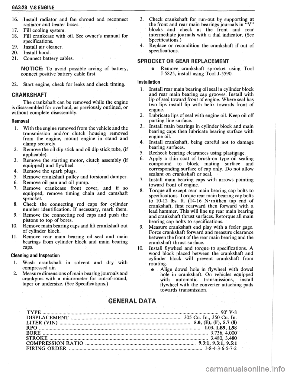
6A3-28 V-8 ENGINE
16. Install
radiator and fan shroud and reconnect
radiator and heater hoses.
17. Fill cooling system.
18. Fill
crankcase with oil. See owner's manual for
specifications.
19. Install air cleaner.
20. Install hood.
21. Connect battery cables.
NOTICE: To avoid possible arcing of battery,
connect positive battery cable first.
22. Start engine, check for leaks and check timing.
CRANKSHAFT
The crankshaft can be removed while the engine
is disassembled for overhaul, as previously outlined, or
without complete disassembly.
Removal
With the engine removed from the vehicle and the
transmission and/or clutch housing removed
from the engine, mount engine in stand and
clamp securely.
Remove the oil dip stick and oil dip stick tube, (if
applicable).
Remove the starting motor, clutch assembly (if
equipped) and flywheel.
Remove the spark plugs.
Remove crankshaft pulley and torsional damper.
Remove oil pan and oil pump.
Remove crankcase front cover, and if so
equipped, remove timing chain and camshaft
sprocket.
Check the connecting rod caps for cylinder
number identification. If necessary, mark them.
Remove the connecting rod caps and push the
pistons to top of bores.
Remove main bearing caps and lift crankshaft out
of cylinder block.
Remove rear main bearing oil seal and main
bearings from cylinder block and main bearing
caps.
Cleaning and Inspection
1. Wash crankshaft in solvent and dry with
compressed air.
2. Measure dimensions of main bearing journals and
crankpins with a micrometer for out-of-round,
taper or undersize. (See Specifications.) 3.
Check crankshaft for run-out by supporting at
the front and rear main bearings journals in
"V"
blocks and check at the front and rear
intermediate journals with a dial indicator. (See
Specifications.)
4. Replace or recondition the crankshaft if out of
specifications.
SPROCKET OR GEAR REPLACEMENT
e Remove crankshaft sprocket using Tool
5-5825, install using Tool J-5590.
Installation
1.
Install rear main bearing oil seal in cylinder block
and rear main bearing cap grooves. Install with
lip of seal toward front of engine. Where seal has
two lips install lip with helix towards front of
engine.
2. Lubricate lips of seal with engine oil. Keep oil off
parting line surface.
3. Install main bearings in cylinder block and main
bearing caps then lubricate bearing surface with
engine oil.
4. Install crankshaft, being careful not to damage
bearing surfaces.
5. Recheck bearing clearances using plastigage.
6. Apply a thin coat of brush-on type oil sealing
compound to block mating surface and
corresponding surface of cap only. Do not allow
sealant on crankshaft or seal.
7. Install main bearing caps with arrows pointing
toward front of engine.
8. Torque all except rear main bearing cap bolts to
specifications. Torque rear main bearing cap bolts
to 10-12 lbs. ft. (14-16
N.m)then tap end of
crankshaft, first rearward then forward with a
lead hammer. This will line up rear main bearing
and crankshaft thrust surfaces.
Retorque all main
bearing cap bolts to specifications.
9. Measure crankshaft end play with a feeler gage.
Force crankshaft forward and measure clearance
between the front of the rear main bearing and the
crankshaft thrust surface.
10. Install flywheel and torque to specifications. A
wood block placed between the crankshaft and
cylinder block will prevent crankshaft from
rotating.
Align dowel hole in flywheel with dowel
hole in crankshaft. On vehicles equipped
with automatic transmissions, install
flywheel with the converter attaching pads
towards transmission.
GENERAL DATA
TYPE .................................................................................................................................. 90" V-8
DISPLACEMENT
............................................................................... 305 Cu. In., 350 Cu. In.
......................................................... LITER (VIN) ................................... ...... 5.0, (E), (F), 5.7 (8)
RPO ......................................................................................................................... L03, LB9, L98
BORE ........................................................................................................................ 3.736, 4.000
STROKE
........................... .. ....................................................................................... 3.480, 3.480
COMPRESSION RATIO
................................................................................... 931, 931, 9.5:1
FIRING ORDER .................................................................................................... 1-8-4-3-6-5-7-2
Page 482 of 1825
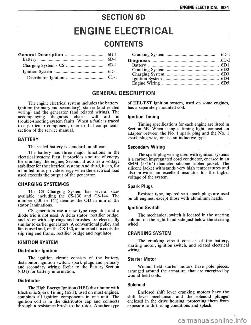
ENGINE ELECTRICAL 6B.l
SECTION 6D
NE ELECTR
General Description ................................... 6D- 1 Cranking System ..................................... 6D- 1
Battery .................... ... .............................. 6D- 1 ....................................................... Diagnosis ,6D-2
.................................. Charging System - CS 6D- 1 Battery ................... .. ..................................... 6D1
......................................... Ignition System ............................................ 6D- 1 Cranking System 6D2
Charging System .......................... .. ............... 6D3 .................................. Distributor Ignition 6D- 1 Ignition Svstem .......................................... 6D4 - Engine Wiring ................................................ 6D5
GENERAL DESCRIPTION
The engine electrical system includes the battery,
ignition (primary and secondary), starter (and related
wiring) and the generator (and related wiring). The
accompanying diagnosis charts will aid in
trouble-shooting system faults. When a fault is traced
to a particular component, refer to that components'
section of the service manual.
BATTERY
The sealed battery is standard on all cars.
The battery has three major functions in the
electrical system: First, it provides a source of energy
for
cranking the engine; Second, it acts as a voltage
stabilizer for the electrical system; And third, it can, for
a limited time, provide energy when the electrical load
used exceeds the output of the generator.
CHARGING SYSTEM-CS
The CS Charging System has several sizes
available, including the CS-130 and CS-144. The
number (130 or 144) denotes the
OD in mm of the
stator laminations.
CS generators use a new type regulator and a
diode trio is not used. A delta stator, rectifier bridge,
and rotor with slip rings and brushes are electrically
similar to earlier generators. A conventional pulley and
fan is used and, on the CS-130, an internal fan cools the
slip ring end frame, rectifier bridge and regulator.
IGNITION SYSTEM
Distributor Ignition
The ignition circuit consists of the battery,
distributor, ignition switch, spark plugs and primary
and secondary wiring. Refer to the Battery Section
(6D 1) for battery information.
Distri but~r
The High Energy Ignition (HEI) distributor with
Electronic Spark Timing (EST), used on most engines,
combines all ignition components in one unit. The
ignition coil is in the distributor cap and connects
through a resistance brush to the rotor. Another type of
HEVEST ignition system,
used on some engines,
has a separately mounted coil.
Ignition Timing
Timing specifications for each engine are listed in
Section 6E. When using a timing light, connect an
adapter between the No. 1 spark plug and the No. 1
spark plug wire, or use an inductive type
Secondary Wiring
The spark plug wiring used with ignition systems
is a carbon impregnated cord conductor, encased in an
8MM (5/16") diameter silicone rubber jacket. The
silicone jacket withstands very high temperatures and
also provides an excellent insulator for the higher
voltage of the system.
Spark Plugs
Resistor type, tapered seat spark plugs are used
on all engines, except those with aluminum heads.
lgnition Switch
The mechanical switch is located in the steering
column on the right hand side just below the steering
wheel.
CRANKING SYSTEM
The cranking circuit consists of the battery,
starting motor, ignition switch, and related electrical
wiring.
Starter Motor
Wound field starter motors have pole pieces,
arranged around the armature, that are energized by
wound field coils.
Solenoid
Enclosed shift lever cranking motors have the
shift lever mechanism and the solenoid plunger
enclosed in the drive housing, protecting them from
exposure to dirt, icing conditions and splash.