1988 PONTIAC FIERO wheel size
[x] Cancel search: wheel sizePage 276 of 1825
REAR AXLE 4B-3
Noise which originates in other places cannot be
corrected by adjustment or replacement of parts in the
differential. It should also be remembered that rear
axle gears, like any other mechanical device, are not
absolutely quiet and should be accepted as being
commercially quiet unless some abnormal noise is
present.
To make a systematic check for axle noise under
standard conditions, observe the following:
1. Select a level smooth asphalt road to reduce tire
noise and body drumming.
2. Check rear axle lubricant to assure correct level,
then drive car far enough to thoroughly warm up
rear axle lubricant.
3. Note speed and RPM at which noise occurs. Then
stop car and with automatic transmission in neutral,
run engine slowly up and down through engine speeds, corresponding to car speed at which noise
was most pronounced, to determine if it is caused by
exhaust, muffler roar or other engine conditions.
4. Tire noise changes with different road surfaces,
but rear axle noise does not. Temporarily
inflating all tires to approximately 50 pounds
pressure for
test purposes only will materially
alter noise caused by tires, but will not affect noise
caused by rear axle. Rear axle noise usually stops
when coasting at speeds under 30 miles per hour;
however, tire noise continues, but with lower
tone, as car speed is reduced. Rear axle noise
usually changes when comparing acceleration
and coast, but tire noise remains about the same.
Distinguish between tire noise and rear axle noise
by noting if noise varies with various speeds or
sudden acceleration and deceleration; exhaust
and axle noise show variations under these
conditions while tire noise remains constant and
is more pronounced at speeds of 20 to 30 miles
per hour. Further check for tire noise by driving
car over smooth pavements or dirt roads (not
gravel) with tires at normal pressure. If noise is
caused by tires, it will noticeably change or
disappear and reappear with changes in road
surface.
5. Loose or rough front wheel bearings will cause
noise which may be confused with rear axle
noises; however, front wheel bearing noise does
not change when comparing drive and coast.
Light application of brakes while holding car
speed steady will often cause wheel bearing noise
to diminish, as this takes some weight off the
bearing. Front wheel bearings may be easily
checked for noise by jacking up the wheels and
spinning them, also by shaking wheels to
determine if bearings are loose.
6. Rear suspension rubber bushings and spring
insulators dampen out rear axle noise when
correctly installed. Check to see that no metallic
contact exists between the spring and spring
opening in frame or between upper and lower
control arm bushings and frame or axle housing
brackets.
Metal-to-metal contact at those points
may result in telegraphing road noise and normal axle
noise which would not be objectionable if
dampened by bushings.
AXLE NOISES
Gear Noise
After the noise has been determined as being in
the
axle by following the above appraisal procedure,
the type of axle noise should be determined to aid in
maki~~g repairs if necessary.
Gear noise (whine) is audible from 20 to
55 mph
under four driving conditions:
1. Drive - Acceleration or heavy pull.
2. Road Load - Car driving load or constant speed.
3. Float
- Using
enough throttle to keep the car from
driving the engine
- car slows down gradually but
engine still pulls slightly.
4. Coast
- Throttle closed and car in gear. Gear
noise most frequently has periods where noise is
more prominent, usually 30 to 40 mph and 50 to
55 mph.
Bearing Noise
Bad bearings generally produce more of a rough
growl or grating sound, rather than the whine typical
of gear noise. Bearing noise frequently "wow-wows" at
bearing rpm, indicating a defective pinion or rear axle
case side bearing. This noise could easily be confused
with rear wheel bearing noise. Inspect and replace as
required.
Rear Wheel Bearing Noise
A rough rear wheel bearing produces a noise
which continues with car coasting at low speed and
transmission in neutral. Noise may diminish some by
gentle braking. With rear wheels jacked up, spin rear
wheels by hand while listening at hubs for evidence of
rough (noisy) wheel bearing.
I(noclc At Low Speeds
Low speed knock can be caused by worn
universal joints or a side gear hub counterbore in a case
that has worn oversize. Inspect and replace universal
joint or case and side gear as required.
Baclclash Clunk
Excessive clunk with acceleration and
deceleration is caused by worn differential pinion shaft,
excessive clearance between axle shaft and side gear
splines, excessive clearance between side gear hub and
counterbore in case worn pinion and side gear teeth,
worn thrust washers and excessive drive pinion and
rear gear backlash. Remove worn parts and replace as
required, selecting close fitting parts when possible.
Adjust pinion and ring gear backlash.
REAR AXLE STANDARD AND LIMITED-SLIP
1. Noise is the same in "Drive" or "Coast".
a. Road noise.
b. Tire noise.
c. Front wheel bearing noise.
Page 277 of 1825
4B-4 REAR AXLE
d. Incorrect driveline angle.
Noise changes on a different type of road.
a. Road noise.
b. Tire noise.
Noise tone lowers as car speed is lowered.
a. Tire noise.
Similar noise is produced with car standing and
driving.
a. Engine noise.
b. Transmission noise.
Vibration. a. Rough rear wheel bearing.
b. Unbalanced
or damaged propeller shaft.
c. Tire unbalance.
d. Worn
universal joint in propeller shaft.
e. Incorrect driveline angle.
f. Mis-indexed propeller shaft at pinion
flange.
g. Pinion
flange
runout too great.
A knock or click approximately every two
revolutions of the rear wheel.
a. A rear wheel bearing.
Noise most pronounced on turns.
a. Rear
axle side gear and pinion noise.
A continuous low pitch whirring or scraping
noise starting at relatively low speed.
a. Pinion bearing noise.
Drive noise, coast noise or float noise.
a. Ring and
pinion gear noise.
Clunk on acceleration or deceleration.
a. Worn rear
axle pinion shaft in case or side
gear hub counterbore in case worn oversize.
b. Insufficient
lubrication on propeller shaft
slip yoke.
c. Worn U-joints on
propeller shaft. Front or
rear.
Groan in "Forward" or "Reverse".
a. Wrong
or contaminated lube in rear axle.
b. Worn bushings.
Chatter on turns.
a. Wrong
or contaminated lube in rear axle.
b. Clutch
cone worn and/or
spring(s) worn.
Clunk or knock on rough road operation.
a. Excessive end play of axle shafts to
differential cross shaft.
b. Worn bushings.
PRE-REPAIR INVESTIGATION AND TROUBLE
DIAGNOSIS
A careful1 diagnosis of the rear axle prior to
disassembly will often reveal valuable information as to
the extent and type of repairs or adjustments necessary.
Since frequent causes of axle noises are improper
backlash, pinion bearing pre-load, or side bearing
pre-load, or a combination, a few simple adjustments
may be all that are necessary to correct a problem.
Therefore, before removing the rear axle from the
housing, the following checks should be made with the
results recorded and analyzed:
1) Backlash; 2) Total Assembly
Preload; 3) Tooth Contact Pattern Test;
4)
Fluid Level; and 5) Fluid Contamination.
Use care at all times to keep dirt and other foreign
matter, such as grinder dust, soot or sand, away from
differential to prevent possibility of subsequent failure.
The pinion and ring gear must be completely
assembled, installed and all pre-load and backlash
adjustments completed prior to the start of this method
of pinion depth setting. The following procedure can
be used in place of the gage method of pinion depth
setting.
Gear Tooth Nomenclature
The side of the ring gear tooth which curves
outward, or is convex, is referred to as the "drive" side.
The concave side is the "coast" side. The end of the
tooth nearest center of ring gear is referred to as the
"toe" end. The end of the tooth farthest away from the
center is the "heel" end. Toe end of tooth is smaller
than heel end.
It is very important that tooth contact be tested
before the rear axle carrier assembly is disassembled.
Variations in the carrier or pinion rear bearing may
cause the pinion to be too far away from, or close to,
the ring gear. Thus, the tooth contact must be tested
and corrected, if necessary, or the gears may be noisy.
Tooth Contact Pattern Test
1. Wipe oil out of carrier and carefully clean each
tooth of ring gear.
2. Use gear marking compound part number
1052351 or equivalent and apply this mixture
sparingly to all ring gear teeth, using a medium
stiff brush. When properly used, the area of
pinion tooth contact will be visible when hand
load is applied.
3. Tighten bearing cap bolts to 75
N.m (55 lb. ft.).
4. Expand
brake shoes using parking brake cables
until a torque of 54 to
70 N-m (40-50 lb. ft.) is
required to turn the pinion.
A test made without loading the gears will not
give a satisfactory pattern. Turn pinion flange
with wrench so that ring gear rotates one full
revolution, then reverse rotation so that ring gear
rotates one revolution in opposite direction.
5. Observe
pattern on ring gear teeth and compare
with Fig. 3.
Effects of Increasing Load on Teeth Contact
Pattern
When "load" on ring and pinion gear is
increased, such as when car is accelerated forward
from standstill or from normal drive, the tooth contact
will tend to spread out and, under very heavy load, will
extend from near toe to near heel on the drive side. The
entire contact also tends to shift toward heel under
increasingly heavier loads and will become somewhat
broader with respect to tops and bottoms of teeth. The
patterns obtained by this tooth contact pattern test
approximate a light load and, for this reason, they will
extend only about halfway.
Page 284 of 1825
REAR AXLE 48-1 1
Rear Wheel Bolt
Remove or Disconnect 1.
1. Raise vehicle on hoist allowing axle to hang
freely. 2.
2. Remove
wheel, tire and brake drum.
3. Using Tool J 6627-A press out stud.
Fig. 4 10 Removing Wheel Bolt
REAR AXLE ASSEMBLY
Install or Connect
Fig. 4 11 Installing Wheel Bolt
UNIT REPAIR
Remove or Disconnect
Place new stud in axle flange hole. Slightly start
stud serrations in hole by firmly pressing back of
stud with your hand.
Place a flat washer on the stud and install a lug
nut with flat side first (tapered face outboard).
Tighten on lug nut drawing stud into flange until
stud head is bottomed on back side of flange.
Remove lug nut.
Reinstall brake drum (or rotor and caliper),
wheel and tire.
Lower vehicle and remove from hoist.
It is not necessary to remove the rear axle
assembly for any normal repairs. However, if the
housing is damaged, the rear axle assembly may be
removed and installed using the following procedure.
Hoist car and support at frame. Hoist must
remain under rear axle housing.
Disconnect both shock absorbers.
Remove bolt securing left side of track bar to
axle.
Remove brake line junction block bolt at axle
housing, then disconnect brake lines at junction
block.
Lower rear axle assembly on hoist and remove
springs.
Remove rear wheels and drums.
Remove rear axle cover and drain lube.
Remove axle shafts.
Disconnect brake lines from axle housing clips.
Remove brake backing plates.
Disconnect lower control arms from axle
housing.
Disconnect torque arm at axle.
Mark propeller shaft and companion flange and
disconnect shaft and support out of the way.
Remove rear axle housing.
Install or Connect
Install rear axle housing.
Install propeller shaft aligning marks made at
time of removal.
Connect torque arm to axle.
Connect lower control arms to axle.
Install brake backing plates.
Connect brake lines to axle housing.
Install axle shafts.
Install axle housing cover.
Install rear wheels and drums.
Raise axle and install springs.
Install brake line to junction block, then mount
junction block on axle housing.
Install track bar to axle.
Connect shock absorbers.
Fill axle and bleed brake system.
Remove supports and lower car.
Disassembly of Rear Axle Assembly
Before attempting any service procedures the
technician must know what type rear axle is to be
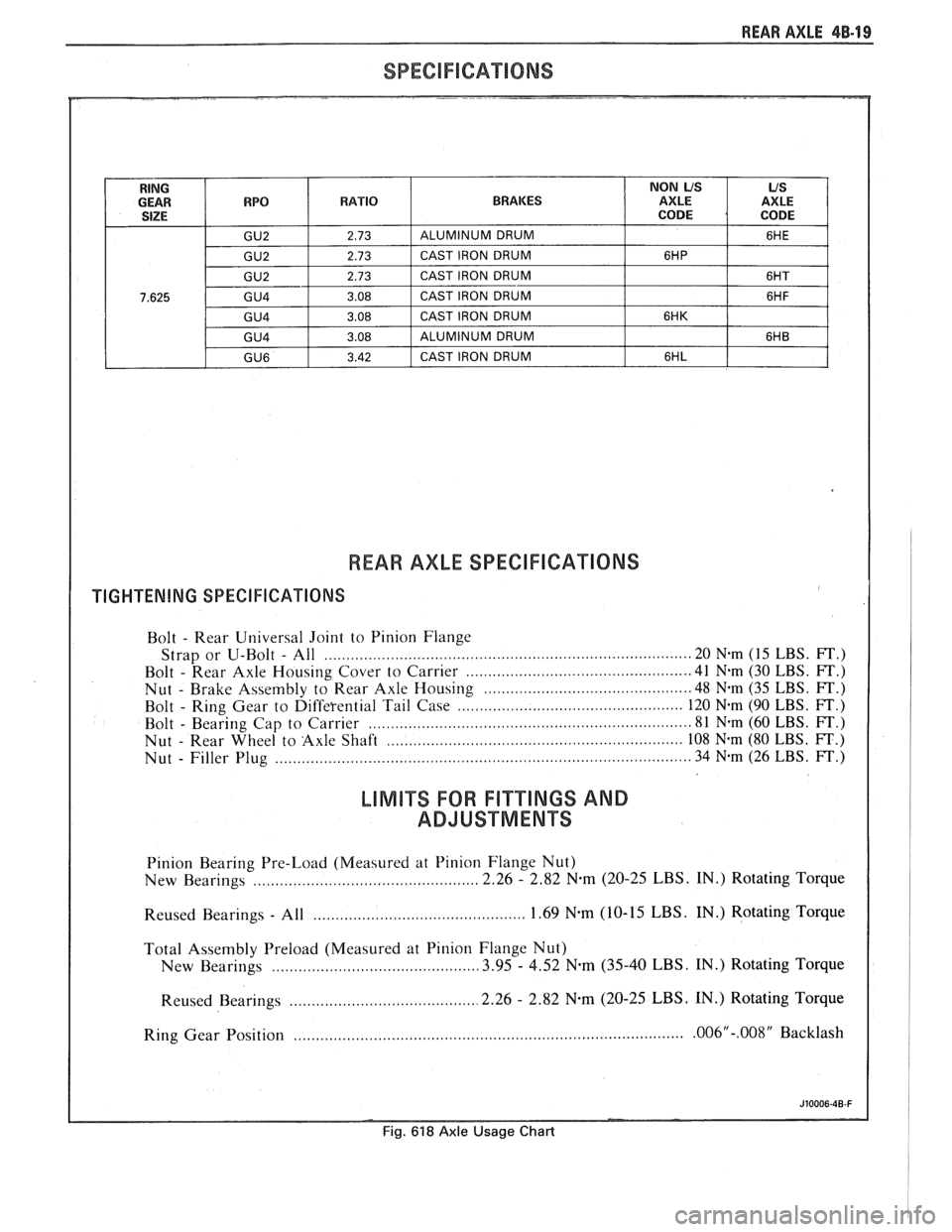
serviced. Refer to chart (Rear Axle Codes And
Identification) to identify codes, ring gear size, and
ratios. Remember that all ring gear bolts have L.H.
threads.
Most rear axle service repairs can be made by
supporting the car by the frame with the axle housing
supported and lowered to its lowest travel. On some
Page 290 of 1825
REAR AXLE 48-1 7
approached. No further tightening should be
attempted until the pre-load has been checked.
7. Check pre-load by using an inch pound torque
wrench.
NOTICE: After pre-load has been checked, final
tightening should be done very carefully. For
example, if when checking, pre-load was found to
be 0.6
N-m (5 lbs. in.), any additional tightening
of the pinion nut can add many additional pound
inch of torque. Therefore, the pinion nut should be
further tightened only a little at a time and the
pre-load should be checked after each slight
amount of tightening. Exceeding pre-load
specifications will compress the collapsible spacer
too far and require the installation of a new
collapsible spacer.
While observing the preceeding note, carefully set
pre-load at 2.7 to 3.6
N-m (24 to 32 1b.in.) on new
bearings or 1.0 to 1.4
N m (8 to 12 1b.in.) on used
bearings.
8. Rotate pinion several times to assure that
bearings have been seated. Check pre-load again.
If pre-load has been reduced by rotating pinion,
reset pre-load to specifications.
Rear Axle Backlash Adjustment
1. Install rear axle case into carrier, using shims as
determined by the side bearing pre-load
adjustment.
2. Rotate rear axle case several times to seat
bearings, then mount dial indicator. Use a small
button on the indicator stem so that contact can
be made near heel end of tooth. Set dial indicator
so that stem is in line as nearly as possible with
gear rotation perpendicular to tooth angle for
accurate backlash reading.
3. Check backlash at three or four points around
ring gear. Lash must not vary over
.05mm (.002")
around ring gear. Pinion must be held stationary
when checking backlash. If variation is over
.05mm (.002") check for burrs, uneven bolting
conditions or distorted case flange and make
corrections as necessary.
4. Backlash at the point of minimum lash should be
between .13 and
.23mm (.005" and ,009") for all
new gears.
5. If backlash is not within specifications, correct by
increasing thickness of one shim and decreasing
thickness of other shim the same amount. This
will maintain correct rear axle side bearing
pre-load.
For each
.03mm (.001") change in backlash
desired, transfer
.05mm (.002") in shim
thickness. To decrease backlash
.03mm (.00lU),
decrease thickness of right shim .05mm (.002")
and increase thickness of left shim .05mm (.
002 "). To increase backlash .05mm (.002 ")
increase thickness of right shim .10mm (.004")
and decrease thickness of left shim .10mm (.
004"). 6.
When backlash is correctly adjusted, remove both
bearing caps and both shim packs.
Keep packs in their respective position, right or
left side.
Select a shim
.10mm (.004") thicker than the one
removed from the left side, then insert left side
shim pack between the spacer and the left bearing
race. Loosely install bearing cap.
7. Select a shim
.10mm (.004") thicker than the one
removed from right side and insert between the
spacer and the right bearing race. It will be
necessary to drive the right shim into position
(Fig. 614).
8. Torque to 75 Nem (55 1b.ft.).
9. Recheck backlash
and correct if necessary.
10. Install axles (See Rear Axle Installation).
11.
Use sealant 1052366 or cover gasket
only.
Install cover and torque cover bolts to 27
N-m (20 1b.ft.).
12. Fill rear axle to proper level with the specified
lubricant. Refer to specifications.
LIMITED SLIP REAR AXLE (GONE TYPE)
The cone-type limited-slip differential has several
definite operating characteristics. An understanding of
these characteristics is necessary as an aid to diagnosis.
The clutch energizing force comes from the
thrust side of the gears. Consequently, a free spinning
wheel may not have enough resistance to drive torque
to apply the clutch cones. If this occurs, apply the
parking brake a few notches which will provide enough
resistance to energize the clutch cones.
Energizing the clutch cones is independent of
acceleration; therefore, a very slow application of the
throttle on starting is recommended to provide
maximum traction by preventing "break away" of
either rear wheel.
Improper operation is generally indicated by cone
slippage or grabbing. Sometimes this produces a
chatter or whirring sound. However, these sounds do
not always indicate failure as they could be produced
from a lack of proper lubrication. For example, under
certain conditions where one wheel is on
a very slippery
surface and the other on dry pavement, wheel spin can
occur if over acceleration is attempted. Continued
spinning may cause audible noise, such as a whirring
sound, due to the cones lacking sufficient lubricant.
This does not necessarily indicate failure of the unit.
During regular operation (straight ahead driving)
when both wheels rotate at equal speeds, there is an
approximately equal driving force delivered to each
wheel. When cornering, the inside wheel delivers extra
driving force causing slippage in both clutch cones.
Consequently, the operational life of the limited slip
unit is dependent upon equal rotation of both wheels
during straight ahead operation. If wheel rotation for
both rear wheels is not equal during straight ahead
operation, the limited-slip unit will constantly be
functioning as if the vehicle were cornering. This will
impose constant slippage on the clutch cones and will
eventually lead to abnormal wear on the clutch cones.
Therefore, it is important that there be no excessive
differences in the rear wheel tire sizes, air pressures, or
Page 291 of 1825
4B-18 REAR AXLE
tire wear patterns. One indication of this condition is
"swerving on acceleration." If swerving on
acceleration is encountered, check the rear wheels for
different tire size, air pressure, or excessively different
wear patterns, and tread depths, before proceeding into
an overhaul operation.
Checking Limited-Slip Operation
1. Place transmisison
in Park position.
2. Raise
rear of vehicle until wheels are off the
ground, remove one wheel and tire assembly.
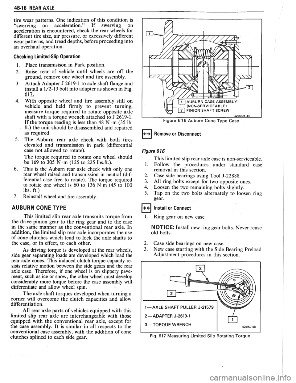
3. Attach Adapter J 2619-1 to axle shaft flange and
install a 1/2-13 bolt into adapter as shown in Fig.
617,
4. With opposite wheel and tire assembly still on
vehicle and held firmly to prevent turning,
measure torque required to rotate opposite axle
shaft with a torque wrench attached to J 2619-1.
If the torque reading is less than 48
N.m (35 lb.
ft.) the unit should be disassembled and repaired
as required.
5. The Auburn rear axle check with both tires
elevated and transmission in park (differential
case not allowed to rotate).
The torque required to rotate one wheel should
be 169 to 305
N-m (125 to 225 1bs.ft.).
6. This is the Auburn rear axle check with only one
rear wheel raised and transmission in neutral (dif-
ferential case free to rotate). The torque required
to rotate one wheel is
60 to 136 N-m (45 to 100
lbs. ft.)
7. Reinstall wheel and tire assembly.
AUBURN CONE TYPE
This limited slip rear axle transmits torque from
the drive pinion gear to the ring gear and to the case
in the same manner as the conventional rear axle. In
addition, the limited slip rear axle incorporates the use
of cone clutches which tend to lock the axle shafts to
the case, or in effect, to each other.
As driving torque is developed at the rear wheels,
side gear separating loads are developed which load the
rear axle cones. This induced clutch torque capacity re-
sists relative motion between the side gears and the rear
axle case. Therefore, if one wheel is on slippery pave-
ment, such as ice or snow, the other wheel must develop
considerably more torque before the case assembly will
differentiate and allow wheel spin.
The axle shaft torques developed when turning a
corner will overcome the clutch capacities and allow
differentiation.
All rear axle parts of vehicles equipped with this
limited slip rear axle are interchangeable with those
equipped with the conventional rear axle, except for
the case assembly. It is similar in all respects to the
conventional case assembly, with the addition of cone
clutches splined to each side gear.
INOWERVICEABLE) PINION SHAFT SCREW
Figure 6 16 Auburn Cone Type Case
Remove or Disconnect
Figure 6 16
This limited slip rear axle case is non-serviceable,
1. Follow the procedures under standard case
removal in this section.
2. Case side bearings using Tool J-22888.
3. All ring bolts except for two opposite ones.
4. Loosen the two remaining bolts slightly.
5. Tap on the two bolts alternately to loosen ring
gear.
Install or Connect
1.
Ring gear on new case.
NOTICE: Install new ring gear bolts. Never reuse
old bolts.
2. Case side bearings on new case.
3. New case starting with the Side Bearing Preload
Adjustment procedures in this section.
1 -AXLE SHAFT PULLER J-21579
2
-ADAPTER J-2619-1
3-TORQUE WRENCH
Fig.
617 Measuring Limited Slip Rotating Torque
Page 292 of 1825
REAR AXLE 48-19
RING NON US US GEAR WPQ RATIO BRAKES AXLE AXLE SIZE CODE CODE
GU2 2.73 ALUMINUM DRUM
6HE
GU2 2.73 CAST IRON DRUM 6HP
GU2 2.73 CAST IRON DRUM
6HT
7.625 G U4 3.08 CAST IRON DRUM 6HF
GU4 3.08 CAST IRON DRUM 6HK
G U4 3.08 ALUMINUM DRUM 6HB
GU6 3.42 CAST IRON DRUM 6HL
REAR AXLE SPEClFICAnONS
TIGHTENING SPECIFICATIONS
Bolt - Rear
Universal Joint to Pinion Flange
Strap or U-Bolt
- All ................................................................................ 20 Nem (15 LBS. FT.)
Bolt
- Rear Axle Housing Cover to Carrier ........................................... 41 N.m (30 LBS. FT.)
Nut
- Brake Assembly to Rear Axle Housing .......................................... 48 N-m (35 LBS. FT.)
Bolt
- Ring Gear to Differential Tail Case ............................................. 120 N.m (90 LBS. FT.)
Bolt
- Bearing Cap to Carrier ....................................................................... 81 N-m (60 LBS. FT.)
Nut
- Rear Wheel to Axle Shaft .................................................................. 108 N-m (80 LBS. FT.)
Nut
- Filler Plug ............................................................................................. 34 N-m (26 LBS. FT.)
LlMlTS FOR FI"TTINGS AND
ADJUSTMENTS
Pinion Bearing Pre-Load (Measured at Pinion Flange Nut)
New Bearings
................................................... 2.26 - 2.82 N-m (20-25 LBS. IN.) Rotating Torque
............................................. Reused Bearings - All 1.69 N-m (10-
15 LBS. IN.) Rotating Torque
Total Assembly Preload (Measured at Pinion Flange Nut)
New Bearings
.......................................... 3.95 - 4.52 N.m (35-40 LBS. IN.) Rotating Torque
.......................................... Reused Bearings 2.26 - 2.82 N.m (20-25 LBS. IN.)
Rotating Torque
Ring Gear Position
........................................................................................ .006"-.008" Backlash
Fig. 618 Axle Usage Chart
Page 301 of 1825
5-8 BRAKES
1 -PEDAL 4-SWITCH
(WITH CRUISE CONTROL)
2- RETAINER
5-PEDAL SUPPORT
3-SWITCH
I lWlO CRUISE CONTROLl J10003-5-F
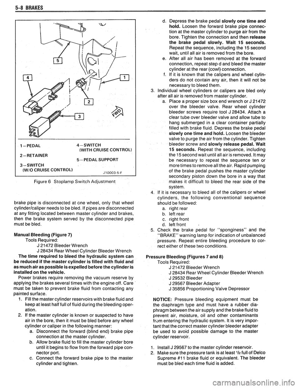
Figure 6 Stoplamp Switch Adjustment
brake pipe is disconnected at one wheel, only that wheel
cylinderlcaliper needs to be bled. If pipes are disconnected
at any fitting located between master cylinder and brakes,
then the brake system served by the disconnected pipe
must be bled.
Manual Bleeding (Figure
7)
Tools Required:
J 21472 Bleeder Wrench
J 28434 Rear Wheel Cylinder Bleeder Wrench
The time required to bleed the hydraulic system can
be reduced if the master cylinder is filled with fluid and
as much air as possible is expelled before the cylinder is
installed on the vehicle.
Power brakes require removing the vacuum reserve by
applying the brakes several times with the engine off. Care
must be taken to prevent brake fluid from contacting any
painted surface.
1. Fill the master cylinder reservoirs with brake fluid and
keep at least half full of fluid during the bleeding oper-
ation.
2.
If the master cylinder is known or suspected to have
air in the bore, then it must be bled before any wheel
cylinder or caliper in the following manner:
a. Disconnect the forward (blind end) brake pipe
connection at the master cylinder.
b. Allow brake fluid to fill the master cylinder bore
until it begins to flow from the forward pipe con-
nector port.
c. Connect the forward brake pipe to the master
cylinder and tighten. d.
Depress the brake pedal slowly one time and
hold. Loosen the forward brake pipe connec-
tion at the master cylinder to purge air from the
bore. Tighten the connection and then release
the brake pedal slowly. Wait
15 seconds.
Repeat the sequence, including the
15 second
wait, until all air is removed from the bore.
e. After all air has been removed at the forward
connection, repeat step d and bleed the master
cylinder at the rear (cowl) connection.
f. If it is known that the calipers and wheel cylin-
ders do not
coiitain any air, then it will not be
necessary to bleed them.
Individual wheel cylinders or calipers are bled only
after all air is removed from master cylinder.
a. Place a proper size box end wrench or
J 21 472
over the bleeder valve. Rear wheel cylinder
bleeder screws require tool
J 28434. Attach a
clear tube over bleeder valve and allow tube to
hang submerged in a clear container partially
filled with brake fluid. Depress the brake pedal
slowly one time and hold. Loosen the bleeder
valve to purge the air from the cylinder. Tighten
bleeder screw and slowly release pedal. Wait
15 seconds. Repeat the sequence, including
the 15 second wait until all air is removed. It may
be necessary to repeat the sequence ten or
more times to remove all the air. Rapid pumping
of the brake pedal pushes the master cylinder
secondary piston down the bore in a way that
makes it difficult to bleed the rear side of the
system.
If it is necessary to bleed all of the calipers or wheel
cylinders, the following conventional sequence
should be followed: a. right rear
b. left rear
c. right front
d. left front
Check the brake pedal for "sponginess" and the
"BRAKE" warning lamp for indication of unbalanced
pressure. Repeat entire bleeding procedure to cor-
rect either of these two conditions.
Pressure Bleeding (Figures
7 and 8)
Tools Required:
J 21472 Bleeder Wrench
J 28434 Rear Wheel Cylinder Bleeder Wrench
J 29532 Bleeder
J 29567 Bleeder Adapter
J 35856 Proportioning Valve Depressor
NOTICE: Pressure bleeding equipment must be
the diaphragm type and must have a rubber dia-
phragm between the air supply and the brake fluid to
prevent air, moisture, oil and other contaminants
fram entering the hydraulic system. It is very impor-
tant that the correct master cylinder bleeder adapter
be used to avoid possible damage to the master
cylinder reservoir.
1. Install J 29567 to the master cylinder reservoir.
2. Make sure the pressure tank is at least
lh full of Delco
Supreme $1 1 brake fluid or equivalent. The bleeder
must be bled each time fluid is added.
Page 302 of 1825
BRAKES 5-9
TUBE hlUST BE
SUBMERGED IN
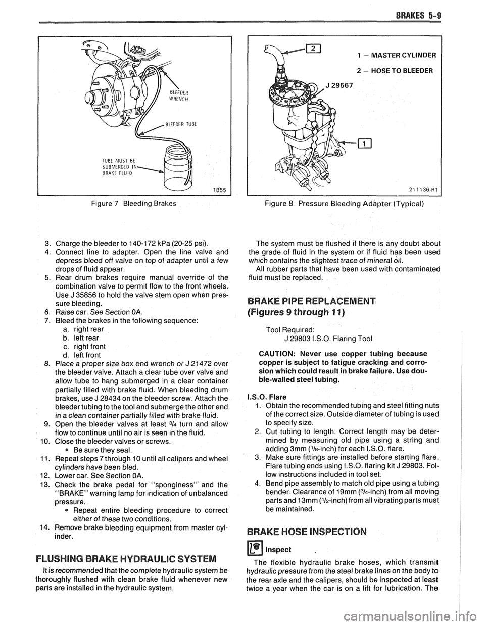
Figure 7 Bleeding Brakes
3. Charge the bleeder to 140-172
kPa (20-25 psi).
4. Connect line to adapter. Open the line valve and
depress bleed off valve on top of adapter until a few
drops of fluid appear.
5. Rear drum brakes require manual override of the
combination valve to permit flow to the front wheels. Use
J 35856 to hold the valve stem open when pres-
sure bleeding.
6. Raise car. See Section
OA.
7. Bleed the brakes in the following sequence:
a. right rear
b. left rear
c. right front
d. left front
8. Place a proper size box end wrench or
J 21472 over
the bleeder valve. Attach a clear tube over valve and
allow tube to hang submerged in a clear container
partially filled with brake fluid. When bleeding drum
brakes, use
J 28434 on the bleeder screw. Attach the
bleeder tubing to the tool and submerge the other end
in a clean container partially filled with brake fluid.
9. Open the bleeder valves at least 3/4 turn and allow
flow to continue until no air is seen in the fluid.
10. Close the bleeder valves or screws.
Be sure they seal.
11. Repeat steps
7 through 10 until all calipers and wheel
cylinders have been bled.
12. Lower car. See Section OA.
13. Check the brake pedal for "sponginess" and the
"BRAKE" warning lamp for indication of unbalanced
pressure.
* Repeat entire bleeding procedure to correct
either of these two conditions.
14. Remove brake bleeding equipment from master cyl-
inder.
FLUSHING BRAKE HYDRAULIC SYSTEM
It is recommended that the complete hydraulic system be
thoroughly flushed with clean brake fluid whenever new
parts are installed in the hydraulic system.
1 - MASTER CYLINDER
u 2 - HOSE TO BLEEDER
Figure 8 Pressure Bleeding Adapter (Typical)
The system must be flushed if there is any doubt about
the grade of fluid in the system or if fluid has been used
which contains the slightest trace of mineral oil.
All rubber parts that have been used with contaminated
fluid must be replaced.
BRAKE PIPE REPLACEMENT
(Figures
9 through 11)
Tool Required:
J 29803 I.S.O. Flaring Tool
CAUTION: Never use copper tubing because
copper is subject to fatigue cracking and corro-
sion which could result in brake failure. Use dou-
ble-walled steel tubing.
I.S.O. Flare
1. Obtain the recommended tubing and steel fitting nuts
of the correct size. Outside diameter of tubing is used
to specify size.
2. Cut tubing to length. Correct length may be deter-
mined by measuring old pipe using a string and
adding 3mm ('la-inch) for each I.S.O. flare.
3. Make sure fittings are installed before starting flare.
Flare tubing ends using I.S.O. flaring kit
J 29803. Fol-
low instructions included in tool set.
4. Bend pipe assembly to match old pipe using a tubing
bender. Clearance of
19mm (314-inch) from all moving
parts and
13mm (lh-inch)from all vibrating parts must
be maintained.
BRAKE HOSE INSPECTION
0 inspect
The flexible hydraulic brake hoses, which transmit
hydraulic pressure from the steel brake lines on the body to
the rear axle and the calipers, should be inspected at least
twice a year when the car is on a lift for lubrication. The