1988 PONTIAC FIERO wheel size
[x] Cancel search: wheel sizePage 1118 of 1825

AUTOMATIC TRANSMISSION 7A-3
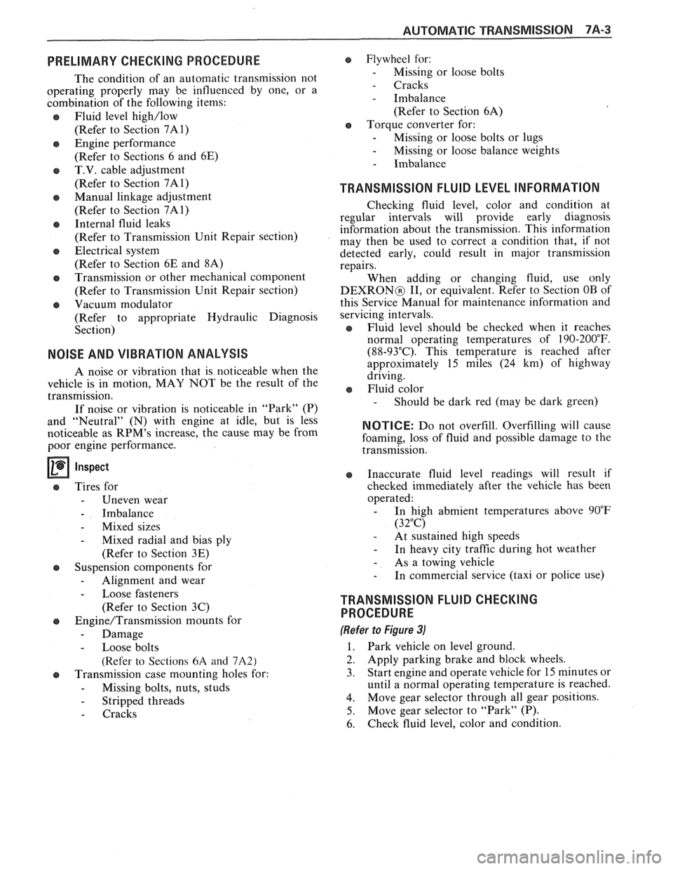
PRELIMARY CHECKING PROCEDURE
The condition of an automatic transmission not
operating properly may be influenced by one, or a
combination of the following items:
e Fluid level high/low
(Refer to Section 7A1)
e Engine performance
(Refer to Sections 6 and 6E)
T.V. cable adjustment
(Refer to Section
7A1)
e Manual linkage adjustment
(Refer to Section
7A1)
e Internal fluid leaks
(Refer to Transmission Unit Repair section)
e Electrical system
(Refer to Section 6E and 8A)
e Transmission or other mechanical component
(Refer to Transmission Unit Repair section)
e Vacuum modulator
(Refer to appropriate Hydraulic Diagnosis
Section)
NOISE AND VIBRATION ANALYSIS
A noise or vibration that is noticeable when the
vehicle is in motion, MAY NOT be the result of the
transmission.
If noise or vibration is noticeable in "Park"
(P)
and "Neutral" (N) with engine at idle, but is less
noticeable as
RPM's increase, the cause may be from
poor engine performance.
e Tires for
- Uneven wear
- Imbalance
- Mixed sizes
- Mixed radial and bias ply
(Refer to Section 3E)
e Suspension components for
- Alignment and wear
- Loose fasteners
(Refer to Section 3C)
e Engine/Transmission mounts for
- Damage
- Loose bolts
(Refer
to Sections 6A and 7A2)
e Transmission case mounting holes for:
- Missing bolts, nuts, studs
- Stripped threads
- Cracks
e Flywheel for:
- Missing or loose bolts
- Cracks
- Imbalance
(Refer to Section 6A)
e Torque converter for: - Missing or loose bolts or lugs - Missing or loose balance weights
- Imbalance
TRANSMISSION FLUID LEVEL INFORMATION
Checking fluid level, color and condition at
regular intervals will provide early diagnosis
information about the transmission. This information
may then be used to correct a condition that, if not
detected early, could result in major transmission
repairs.
When adding or changing fluid, use only
DEXRONO 11, or equivalent. Refer to Section OB of
this Service Manual for maintenance information and
servicing intervals.
Fluid level should be checked when it reaches
normal operating temperatures of
190-200°F.
(88-93°C). This temperature is reached after
approximately 15 miles (24 km) of highway
driving.
e Fluid color - Should be dark red (may be dark green)
NOTICE: Do not overfill. Overfilling will cause
foaming, loss of fluid and possible damage to the
transmission.
Inaccurate fluid level readings will result if
checked immediately after the vehicle has been
operated:
- In high abmient temperatures above 90°F
(32°C)
- At sustained high speeds
- In heavy city traffic during hot weather
- As a towing vehicle - In commercial service (taxi or police use)
TRANSMISSION FLUID CHECKING
PROCEDURE
(Refer to Figure 3)
1. Park vehicle on level ground.
2. Apply parking
brake and block wheels.
3. Start
engine and operate vehicle for 15 minutes or
until a normal operating temperature is reached.
4. Move gear
selector through all gear positions.
5. Move
gear selector to "Park" (P).
6. Check fluid level, color and condition.
Page 1551 of 1825

RADIO
(Continued from previous page)
1. Remove the Cancel Cam. Inspect the Slip
Rings on the Cancel Cam and the spring
loaded contacts on the Turn Signal
Switch. Replace as necessary. Incorrect
or missinglubricant on the Cam can cause
premature failure. Take care to keep lubri-
cant or any foreign material away from
the
LED'S and receptors as it will hinder
or prevent proper operation. The correct
lubricant is part no.
26002312.
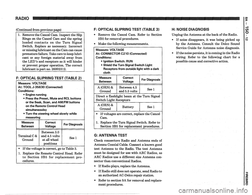
F: OPTICAL SLlPRlNG TEST (TABLE 2)
Measure: VOLTAGE
At: TOOL J-35630 (Connected)
Conditions:
@ Engine running
0 Press the Preset, Mute and RCL buttons
or the Seek, Scan, and
AMIFM buttons
on the Remote Control Head
sirnultaneoulsy
0 Turn the steering wheel slowly while
measuring
Measure
Correct I For Diagnosis I
I I Between 3.0 1 I Terminal C & and 4.5 volts
1 Ground 1 at all wheel
I 1 positions I I
I . If the voltage is correct, go to Table 3. (
1. Replace the Remote Control Head. Refer
to Section
3B5 for replacement pro-
cedures.
F: OPTICAL SLlPRllUG TEST (TABLE 3) H: NOlSE DIAGNOSIS
Remove the Cancel Cam. Refer to Section Unplug
the Antenna at the back of the Radio.
3B5 for removal procedures.
If noise disappears, it was being picked up
0 Make the following measurements.
by the Antenna. Consult the Delco Sound
Service Guide for Antenna noise diagnosis.
If the noise persists, it is coming in the Radio
wiring. Refer to the following chart for a
possible cause and corrective action.
At: CONNECTOR 6210 (Connected)
@ Ignition Switch: RUN
Shield the Turn Signal Switch Light
Receptors from outside light with a dark
1. Replace the Turn Signal Switch. Refer to
6: ANTENNA TEST
Check connectors Radio and Antenna ends of
Antenna Coaxial Cable. Connect a known good
test Antenna to the Radio. The test Antenna
must be designed for use
with ARC Radios, as
ARC Radios use a different size Antenna con-
nector than conventional Radios.
@ If Radio plays, replace the Antenna.
If Radio still does not operate, send Radio to
an authorized AC-Delco repair station.
Refer to section 9A for removal and replace-
ment procedures.
Page 1791 of 1825

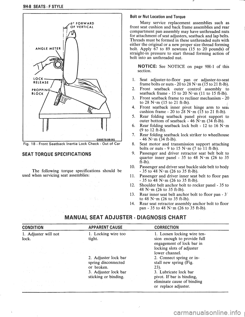
9H-8 SEATS. F STYLE Bolt or Nut Location and Torque
6O FORWARD Many service replacement assemblies such as
OF VERTICAL front seat cushion and back frame assemblies and rear
compartment pan assembly may have unthreaded nuts
for attachment of seat adjusters,
seatback and lap belts.
Threads must be formed in these unthreaded nuts with
either the original or a new proper size thread forming
ANGLE METER bolt. Apply 67 to 89 newtons (15 to 20 pounds) of
straight-in pressure to start thread forming action of
bolt into an unthreaded nut.
NOTIICE: See NOTICE on page 9H-1 of this
section.
1. Seat adjuster-to-floor pan or adjuster-to-seat
frame bolts or nuts
- 20 to 28 N-m (15 to 21 ft-lb).
2. Front seatback outer control assembly to
seatback frame - 15 to 20 N-m (1 1 to 15 ft-lb).
3. Front
seatback frame to recliner mechanism - 20
to 28
N-m (15 to 21 ft-lb). I 4. Front seatback inner pivot hinge arm to seai
cushion frame - 20 to 28 N.m (15 to 21 ft-lb).
5. Rear folding
seatback panel pivot support to
outer bottom of
seatback - 46 N-m (34 ft-lb).
6. Rear folding
seatback lock bolt - 12 to 16 N.m
(9 to 12 ft-lb).
7. Rear folding
seatback lock striker to wheelhouse
- 46 N.m (34 ft-lb).
Fig. 18 - Front Seatback Inertia Lock Check - Out of Car 8. Seat
motor and transmission support attaching
bolts or nuts
- 9 to 15 N.m (7 to 11 ft-lb).
SEAT TORQUE SPECIFICATIONS 9. Passenger and driver retractor seat belt bolt to
quarter inner panel
- 35 to 48 N-m (26 to 35
ft-lb).
10. Passenger and driver seat buckle side belt to body
The following torque specifications should be
- 35 to 48 N.m (26 to 35 ft-lb).
used when servicing seat assemblies:
11. Passenger and driver inner seat belt to floor pan
- 35 to 48 N.m (26 to 35 ft-lb).
12. Shoulder belt anchor bolt to rocker panel
- 35 to
48
Nam (26 to 35 ft-lb).
13. Rear inner seat belt anchor bolt to floor pan
- 3'
to 48
Nqm (26 to 35 ft-lb).
14. Rear seat retractor assembly anchor bolt to floor
pan
- 35 to 48 N-m (26 to 35 ft-lb).
MANUAL SEAT ADJUSTER - DIAGNOSIS CHART
CONDITION APPARENTCAUSE CORRECTION
1. Adjuster will not 1. Locking wire
too
1. Loosen locking wire ten-
lock. tight. sion enough to provide full
engagement of lock bar in
locking slots of adjuster
lower channel.
2. Adjuster lock bar 2. Connect spring or
in-
spring disconnected stall new spring (Fig.
or broken. 23).
3. Adjuster lock bar 3. Lubricate lock bar
sticking or binding.
pivot. If bar is binding,
eliminate cause of binding
or replace adjuster.