1988 PONTIAC FIERO maintenance
[x] Cancel search: maintenancePage 309 of 1825
5-16 BRAKES
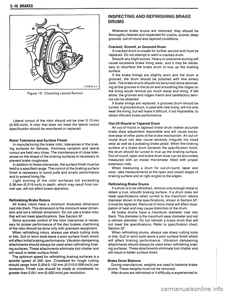
Figure 15 Checking Lateral Runout
Lateral runout of the rotor should not be over 0.13 mm
(0.005-inch). A rotor that does not meet the lateral runout
specification should be resurfaced or replaced.
Rotor Tolerance and Surface Finish
In manufacturing the brake rotor, tolerances of the brak-
ing surfaces for flatness, thickness variation and lateral
runout are held very close. The maintenance of close toler-
ances on the shape of the braking surfaces is necessary to
prevent brake roughness. In addition to these tolerances, the surface finish must be
held to a specified range. The control of the braking surface
finish is necessary to avoid pulls and erratic performance
and to extend lining life.
Light scoring of the rotor surfaces not exceeding
0.38
mrn (0.015-inch) in depth, which may result from nor-
mal use, will not affect brake operation.
Refinishing Brake Rotors
All brake rotors have a minimum thickness dimension
cast into them. This dimension is the minimum wear dimen-
sion and not a refinish dimension. Do not use a brake rotor
that will not meet specifications. See Section
5F.
Since accurate control of the rotor tolerances is neces-
sary for proper performance of the disc brakes, machining
of the rotor should be done only with precision equipment.
When refinishing rotors, always use sharp cutting tools
or bits. Dull or worn tools leave a poor surface finish which
will affect initial braking performance. Vibration dampening
attachments should always be used when refinishing brak-
ing surfaces. These attachments eliminate tool chatter and
will result in better surface finish.
The optimum speed for refinishing braking surfaces is a
spindle speed of 200 rpm. Crossfeed for rough cutting
should range from 0.254-0.152 mm (0.010-0.006-inch) per
revolution. Finish cuts should be made at crossfeeds no
greater than 0.051 mm (0.002-inch) per revolution.
INSPECTING AND REFlNlSHlMG BRAKE
DRUMS
Whenever brake drums are removed, they should be
thoroughly cleaned and inspected for cracks, scores, deep
grooves, out-of-round and tapered conditions.
Cracked, Scored, or Grooved Drum
A cracked drum is unsafe for further service and must be
replaced. Do not attempt to weld a cracked drum.
Smooth any slight scores. Heavy or extensive scoring will
cause excessive brake lining wear, and it may be neces-
sary to resurface the brake drum to true up the braking
surface.
If the brake linings are slightly worn and the drum is
grooved, the drum should be polished with fine emery
cloth. The brake drums should not be turned since eliminat-
ing all the grooves in the drum and smoothing the ridges on
the lining would remove too much metal and lining. If left
alone, the grooves and ridges match and satisfactory serv-
ice can be obtained. If brake linings are replaced, a grooved drum should be
turned. Agrooved drum, if used with new lining, will not only
wear the lining, but will make it difficult, if not impossible, to
obtain efficient brake performance.
But-Of-Round or Tapered Drum
An out-of-round or tapered brake drum makes accurate
brake shoe adjustment impossible and will cause exces-
sive wear of other parts of the brake mechanism. An out-of-
round drum can also cause severely irregular tire tread
wear as well as a pulsating brake pedal. When the braking
surface of a brake drum exceeds the specification limits,
the drum should be turned to true up the braking surface.
Out-of-round, taper and brake drum wear can be accurately
measured with an inside micrometer fitted with proper
extension rods. When measuring a drum for out-of-round, taper and
wear, take measurements at the open and closed edges of
braking surface and at right angles to the edges.
Refinishing Brake Drums
If adrum is to be refinished, remove only enough metal to
obtain a true, smooth braking surface. If a drum does not
meet specifications when turned to the maximum
rebore
diameter shown in the specifications, shown in Section 5F,
it must be replaced. Removal of more metal will affect dissi-
pation of heat and may cause distortion of the drum.
All brake drums have a maximum diameter cast into
them. This diameter is the maximum wear diameter and not
a refinish diameter. Do not refinish a brake drum that will
not meet the specifications. Refer to specification chart,
Section 5F. When refinishing drums, always use sharp cutting tools
or bits. Dull or worn tools leave a poor surface finish which
will affect braking performance. Vibration dampening
attachments should always be used when refinishing brak-
ing surfaces. These attachments eliminate tool chatter and
will result in better surface finish.
Brake Drum Balance
During manufacture, weights are used to balance brake
drums. These weights must not be removed.
After drums are refinished or if difficulty is experienced in
Page 464 of 1825
CHARGING SYSTEM 6D3-1
SECTION 6D3
CHARG NG SYSTEM
CONTENTS
General Description ................................. 6D3- 1 Charging System ........................................ 6D3- 1
.......................................... Charging System - CS ............................... 6D3- 1 On-Car Service 6D3-2
................................................... Diagnosis .. 6D3- 1 Generator 6D3-3 ...................... ......................... ............................................. 6D3- 1 Specifications 6D3-3 Service Procedures .................................. Unit Repair .. 6D3-4-6 ............................... ............
GENERAL DESCRIPTION
The engine electrical system includes the battery,
ignition (primary and secondary), starter (and related
wiring) and the generator (and related wiring).
Diagnostic charts (see Section 6D) will aid in
trouble-shooting system faults. When a fault is traced
to a particular component, refer to that components'
section of the service manual.
CHARGING SYSTEM-CS
The CS Charging System has several sizes
available, including the CS-130 and CS-144. The
number (130 or 144) denotes the
OD in mm of the
stator laminations.
CS generators use a new type regulator and a
diode trio is not used. A delta stator, rectifier bridge,
and rotor with slip rings and brushes are electrically
similar to earlier generators. A conventional pulley and
fan is used and, on the CS-130, an internal fan cools the
slip ring end frame, rectifier bridge and regulator.
Unlike three-wire generators, the CS-130 and
CS-144 may be used with only two connections
-
battery positive and an "L" terminal to the charge
indicator bulb. Use of "P",
"F", and "S" terminals is
optional. The "P" terminal is connected to the stator,
and may be connected externally to
a tachometer or other
device. The
"F" terminal is connected internally
to field positive, and may be used as a fault indicator.
The "S" terminal may be connected externally to a
voltage, such as battery voltage, to sense voltage to be
controlled.
As on other charging systems, the charge
indicator lights when the switch is closed, and goes out
when the engine is running. If the charge indicator is
on with the engine running, a charging system defect
is indicated. For all kinds of defects, the indicator will
glow at full brilliance, not "half lit". Also, the charge
indicator will be on with the engine running if system
voltage is too high or too low. The regulator voltage
setting varies with temperature, and limits system
voltage by controlling rotor field current.
This regulator switches rotor field current on and
off at a fixed frequency of about 400 cycles per second.
By varying the on-off time, correct average field
current for proper system voltage control is obtained.
At high speeds, the on-time may be 10% and the
off-time 90%. At low speeds, with high electrical loads,
on-off time may be 90% and
lo%, respectively.
No periodic maintenance on the generator is
required.
DIAGNOSIS
SERVICE PROCEDURES
CHARGING SYSTEM
The generator does not require periodic
lubrication. The rotor shaft is mounted on ball bearings
at the drive end and roller bearings at the slip ring end.
Each contains a permanent grease supply. At periodic
intervals, check mounting bolts for tightness and adjust
belt tension (see Section
6B), if applicable.
e When adjusting belt tension, apply pressure at
center of generator, never against either end
frame.
GENERATOR BENCH CHECK-CS
To check generator in a test stand, remove as
specified in On-Car Service and proceed as follows: 1.
Make connections as shown in Figure
lH, except
leave the carbon pile disconnected. The ground
polarity of generator and battery must be the
same. The battery must be fully charged. Use a
30-500
OHM resistor between battery and "L"
terminal.
2. Slowly increase generator speed and observe
voltage.
3. If the voltage is uncontrolled and increases above
16.0 volts, the rotor field is shorted, the regulator
is defective, or both.
A shorted rotor field coil can
cause the regulator to become defective. NOTE:
The battery must be fully charged when making
this test.
Page 613 of 1825
6EZ-C6-2 5.OL (VIN E) DRIVEABILITY AND EMISSIONS
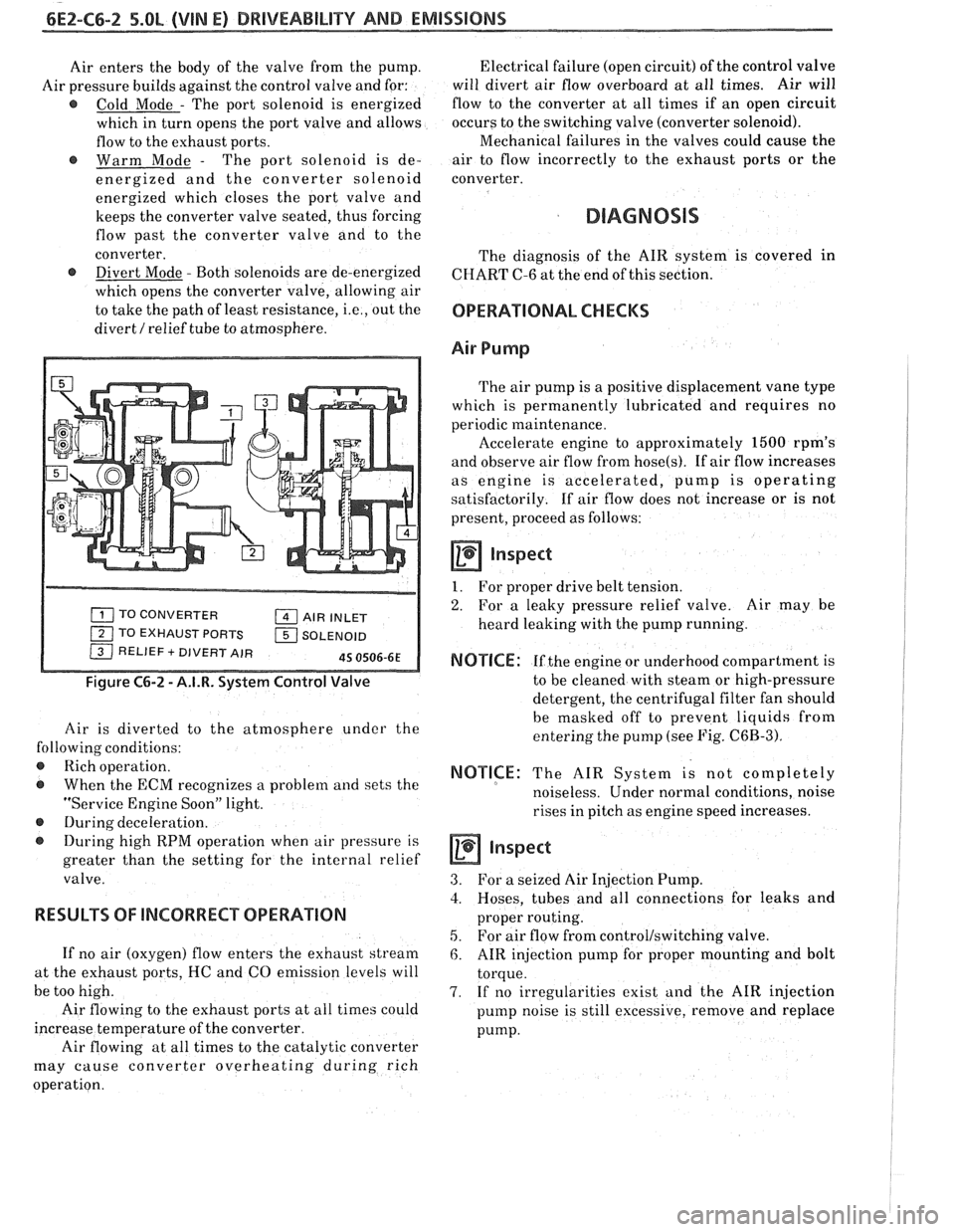
Air enters the body of the valve from the pump.
Air pressure builds against the control valve and for:
@ Cold Mode - The port solenoid is energized
which in turn opens the port valve and allows
flow to the exhaust ports.
@ Warm Mode - The port solenoid is de-
energized and the converter solenoid
energized which closes the port valve and
keeps the converter valve seated, thus forcing
flow past the converter valve and to the
converter.
@ Divert Mode - Both solenoids are de-energized
which opens the converter valve, allowing air
to take the path of least resistance,
i.e., out the
divert
/ relief tube to atmosphere.
TO CONVERTER AIR INLET
1 TO EXHAUST PORTS 1 SOLENOID / RELIEF + DIVERT AIR 45 0506-6E
Figure C6-2 - A.I.R. System Control Valve
Air is diverted to the atmosphere under the
following conditions:
@ Rich operation.
@ When the ECM recognizes a problem and sets the
"Service Engine Soon" light.
@ During deceleration.
During high RPM operation when air pressure is
greater than the setting for the internal relief
valve.
RESULTS OF lNCORRECP OPERATION
If no air (oxygen) flow enters the exhaust stream
at the exhaust ports, HC and CO emission levels will
be too high.
Air flowing to the exhaust ports at all times could
increase temperature of the converter.
Air flowing at all times to the catalytic converter
may cause converter overheating during rich
operation. Electrical failure
(open circuit) of the control valve
will divert air flow overboard at all times. Air will
flow to the converter at all times if an open circuit
occurs to the switching valve (converter solenoid).
Mechanical failures in the valves could cause the
air to flow incorrectly to the exhaust ports or the
converter.
DIAGNOSIS
The diagnosis of the AIR system is covered in
CHART C-6 at the end of this section.
OPERATIONAL CHECKS
Air Pump
The air pump is a positive displacement vane type
which is permanently lubricated and requires no
periodic maintenance.
Accelerate engine to approximately
1500 rpm's
and observe air flow from
hose(s). If air flow increases
as engine is accelerated, pump is operating
satisfactorily. If air flow does not increase or is not
present, proceed as follows:
a Inspect
1. For proper drive belt tension.
2. For a leaky pressure relief valve. Air may be
heard leaking with the pump running.
NOTICE: If the engine or underhood compartment is
to be cleaned with steam or high-pressure
detergent, the centrifugal filter fan should
be masked off to prevent liquids from
entering the pump (see Fig.
C6B-3).
NOTICE: The AIR System is not completely
noiseless. Under normal conditions, noise
rises in pitch as engine speed increases.
inspect
3. For a seized Air Injection Pump.
3. Hoses, tubes and all connections for leaks and
proper routing.
5. For air flow from control/switching valve.
6. AIR injection pump for proper mounting and bolt
torque.
7. If no irregularities exist and the AIR injection
pump noise is still excessive, remove and replace
pump.
Page 771 of 1825
6E3-C6-2 2.8L (WIN 5) DRIVEABILITY AND EMISSIONS
When the solenoid is de-energized, the pressurized
air from the air pump is allowed to enter the decel
timing chamber. This places sufficient pressure on
the metering valve diaphragm to overcome spring
tension, closing the
valve,causing air to divert to the
silencer.
At higher engine speeds, excess air is exhausted to
the silencer through the pressure relief valve. (Figure
C6-1)
Deceleration Valve
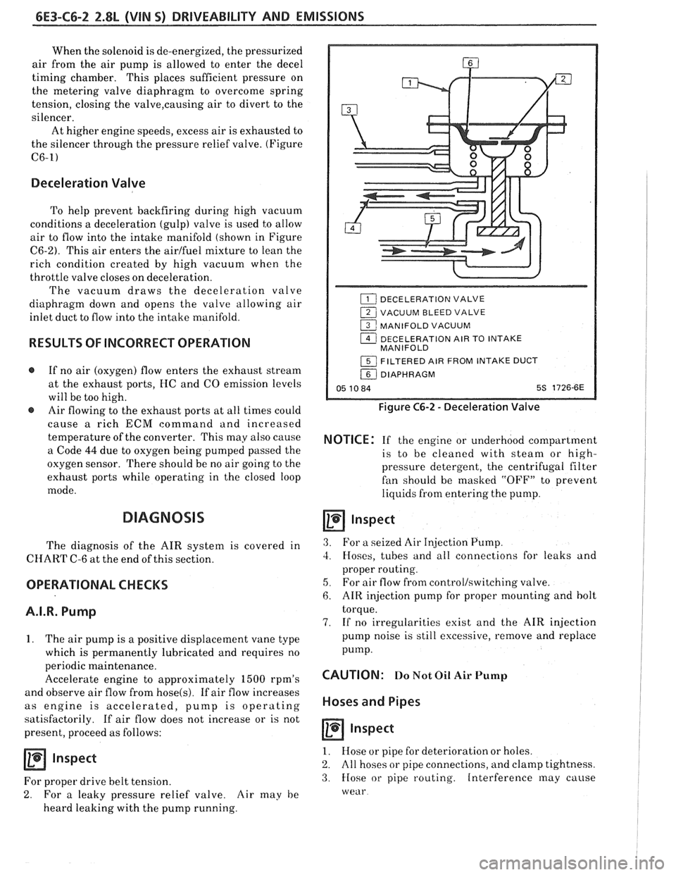
To help prevent backfiring during high vacuum
conditions a deceleration (gulp) valve is used to allow
air to flow into the intake manifold (shown in Figure
C6-2). This air enters the airlfuel mixture to lean the
rich condition created by high vacuum when the
throttle valve closes on deceleration.
The vacuum draws the deceleration valve
diaphragm down and opens the valve allowing air
inlet duct to flow into the intake manifold.
RESULTS OF INCORRECT OPERATION
@ If no air (oxygen) flow enters the exhaust stream
at the exhaust ports, HC and
CO emission levels
will be too high.
@ Air flowing to the exhaust ports at all times could
cause
a rich ECM command and increased
temperature of the converter. This may also cause
a Code
44 due to oxygen being pumped passed the
oxygen sensor. There should be no air going to the
exhaust ports while operating in the closed loop
mode.
DIAGNOSIS
The diagnosis of the AIR system is covered in
CHART C-6 at the end of this section.
OPERATIONAL CHECKS
A.I.R. Pump
1. The air pump is a positive displacement vane type
which is permanently lubricated and requires no
periodic maintenance.
Accelerate engine to approximately
1500 rpm's
and observe air flow from
hose(s). If air flow increases
as engine is accelerated, pump is operating
satisfactorily. If air flow does not increase or is not
present, proceed as follows:
Inspect
For proper drive belt tension.
2. For a leaky pressure relief valve. Air may he
heard leaking with the pump running.
DECELERATION VALVE
1 VACUUM BLEED VALVE
1 MANIFOLD VACUUM
1 DECELERATION AIR TO INTAKE
MANIFOLD
1 FILTERED AIR FROM INTAKE DUCT
/ DIAPHRAGM
05 10 84 5s 1726-6E
Figure C6-2 - Deceleration Valve
NOTICE: If the engine or underhood compartment
is to he cleaned with
steam or high-
pressure detergent, the centrifugal filter
fan should be masked "OFF7' to prevent
liquids from entering the pump.
Inspect
3. For a seized Air Injection Pump.
3. Hoses, tubes and all connections for leaks and
proper routing.
5, For air flow from controllswitching valve.
6. AIR injection pump for proper mounting and bolt
torque.
7. If no irregularities exist and the AIR injection
pump noise is still excessive, remove and replace
pump.
CAUTION: Do Not Oil Air Pump
Hoses and Pipes
Inspect
1. Hose or pipe for deterioration or holes.
2. All hoses or pipe connections, and clamp tightness.
3. Hose or pipe routing. Interference may cause
wear
Page 929 of 1825
6E3-C6-2 5.OL (VIN F) & 5.7L (VIN 8) DRIVEABILITY AND EMISSIONS
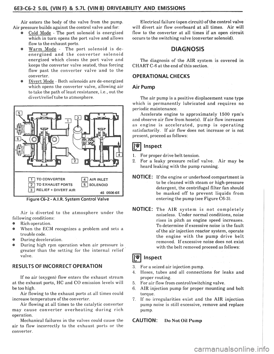
Air enters the body of the valve from the pump.
Air pressure builds against the control valve and for:
@ Cold Mode - The port solenoid is energized
which in turn opens the port valve and allows
flow to the exhaust ports.
Warm Mode
- The port solenoid is de-
energized and the converter solenoid
energized which closes the port valve and
keeps the converter valve seated, thus forcing
flow past the converter valve and to the
converter.
@ Divert Mode - Both solenoids are de-energized
which opens the converter valve, allowing air
to take the path of least resistance,
i.e., out the
divertlrelief tube to atmosphere. Electrical
failure (open circuit) of the control valve
will divert air flow overboard at all times. Air will
flow to the converter at all times if an open circuit
occurs to the switching valve (converter solenoid).
DIAGNOSIS
The diagnosis of the AIR system is covered in
CHART C-6 at the end of this section.
OPERATIONAL CHECKS
Air Pump
The air pump is a positive displacement vane type
which is permanently lubricated and requires no
periodic maintenance.
llccelerate engine to approximately 1500 rpm's
and observe air flow from hose(s). If air flow increases
as engine is accelerated, pump is operating
satisfactorily. If air flow does not increase or is not
present, proceed as follows:
Inspect
I. For proper drive belt tension.
2. For a leaky pressure relief valve. Air may be
heard leaking with the pump running.
TO CONVERTER AIR INLET
TO EXHAUST PORTS
1 SOLENOID
Figure C6-2 - A.I.R. System Control Valve
Air is diverted to the atmosphere under the
lowing conditions:
Rich operation.
When the
ECM recognizes a problem and sets a
trouble code.
@ During deceleration.
During high rprn operation when air pressure is
greater than the setting
for the internal relief
valve.
RESULTS OF INCORRECT OPERATION
If no air (oxygen) flow enters the exhaust stream
at the exhaust ports, I-IC and CO emission levels will
be too high.
Air flowing to the exhaust ports at all times could
increase temperature of the converter.
Air flowing at all times to the catalytic converter
may cause converter overheating during rich
a ion.
oper
t'
Mechanical failures in the valves could cause the
air to flow incorrectly to the exhaust ports or the
converter.
NOTICE : If the engine or underhood compartment is
to be cleaned with steam or high-pressure
detergent, the centrifugal filter fan should
be masked off to prevent liquids from
entering the pump (see Figure
C6-3).
NOTICE: The AIR system is not completely
noiseless. Under normal conditions, noise
rises in pitch as engine speed increases.
To determine if excessive noise is the fault
of the air injection reactor system, operate
the engine with the pump drive belt
removed. If excessive noise does not exist
with the belt removed proceed as follows:
a inspect
3. For a seized air injection pump.
4. Hoses, tubes and all connections for leaks and
proper routing.
5. For air flow from control/switching valve.
6. AIR injection pump for proper mounting and bolt
torque.
7. If no irregularities exist and the AIR injection
pump noise is still excessive, remove and replace
Pump.
CAUTION: 110 Not Oil Pump
Page 962 of 1825
DRIVEABILITY AND EMISSIONS . FUEL INJECIION 6E-1
DRBVEABILIW AND EMISSIONS
CONEENTS
General Information . Section 6E
Driveability and Emissions . Fuel Injected (TBI) . Section 6EZ
Driveability and Emissions . Fuel injected (PORT) . Section 6E3
..................... DRIVEABILITY 6E-1
........................ EMISSIONS 6E-1
MAINTENANCE SCHEDULE ............ 6E-1
VEHICLE EMISSIONS CONTROL
............. INFORMATION UBEL 6E-3
.................... INTRODUCTION 6E-3
.......... Electronic Engine Control 6E-3
What This Section Contains .......*. 6E-3
............. Blocking Drive Wheels 6E-3
.............. Cold Oxygen Sensor 6E-3
VISUAUPHYSICAL UNDERWOOD
..................... INSPECTION 6E-3
BASIC KNOWLEDGE REQUIRED ........ 6E-3
.............. Basic Electric Circuits 6E-3
Use of Circuit Testing Tools ......... 6E-4
Use of Digital Volt-Ohm Meter (DVM) . . 6E-4
DIAGNOSTIC INFORMATION .......... 6E-4
"Service Engine Soon" Light ........ 6E-4
Intermit . "Service Engine Soon" Light . . 6E-4
................... Trouble Codes 6E-4
.................. ALDL Connector 6E-4
Diagnostic Mode ................. 6E-4
Field Service Mode ................ 6E-5
............ Clearing Trouble Codes 6E-5
............. ECM Learning Ability 6E-5
DRIVEABILITY AND EMISSIONS ......... 6E-5
SECTIONS 6E2 and 6E3 SUMMARY ...... 6E-5
SECTION A ....................... 6E-6
Diagnostic Procedure Summary ...... 6E-6
ALDL "SCAN" TOOLS ................ 6E-6
Normal (Open) Mode ............. 6E-6
ALDL (1 OK. or Special) Mode ......... 6E-7
Factory Test (Backup or 3.9K) Mode .... 6E-7
DRIVEABILITY
The driveability diagnosis procedures apply to
various systems in current GM vehicles
. The
procedures assume that the vehicle worked right at
one time and the problem is due to time, wear. dirt or
other causes
. Start with the introduction that follows .
This will describe a systematic diagnostic procedure .
Any system disconnected during diagnosis should
be reconnected
. This includes wires, hoses. linkage.
etc . When removing air cleaner. plug hose fittings
that could cause an air leak
.
"SCAN" TOOLS LIMITATIONS AND USE ... 6E-7
Intermittent Conditions ........... 6E-7
"SCAN" TOOL POSITIONS ............ 6E-7
SECTION B . DRIVEABILITY SYMPTOMS . . 6E-10
SECTION C- COMPONENT SYSTEMS ..... 6E-10
Electronic Control Module (ECM) ..... 6E-10
Fuel Control System ............... 6E-10
Electric Fuel Pump (In-tank) ........ 6E-10
....... Evaporative Emission Control 6E-10
Electronic Spark Timing (EST) ....... 6E-10
....... Electronic Spark Control (ESC) 6E-10
Air Injection Reaction (A.I.R.). ........ 6E-10
......... Early Fuel Evaporation (EFE) 6E-10
Exhaust Gas Recirculation (EGR) ...... 6E-11
Transmission Convefler Clutch (TCC) . . 6E-11
.............. Shift Light Control ; . 6E-I I
................ NC Clutch Control 6E-11
........ Electric Cooling Fan Control 6E-11
Positive Crankcase Ventilation (PCV)
...... or Crankcase Ventilation (CV) 6E-11
Thermostatic Air Cleaner (THERMAC) . . 6E-11
ABBREVIATIONS & GLOSSARY OF TERMS .. 6E-1 1
............ WIRING HARNESS SERVICE 6E-14
......................... GENERAL 6E-14
WIREHARNESS.... ............*.... 6E-15
CONNECTORS .....e..e..ee...~.e.. 6E-15
................... Weather-Pack 6E-15
.................. Compact Three 6E-16
Metri-Pack Series 150 . Terrn'l Removal 6E-16
...................... Micro-Pack 6E-16
...... TOOLS NEED TO SERVICE SYSTEM 6E-17
GENERAL SPECIFICATIONS ............. 6E-23
EMISSIONS
The exhaust emission control systems used on
General Motors engines perform a specific function to
lower exhaust emissions while maintaining good fuel
economy and driveability
.
MAINTENANCE SCHEDULE
Refer to the General Motors Maintenance
Schedule in Section
"OB" of the Chassis Service
Manual for the maintenance service that should be
performed to retain emission control performance
.
Page 986 of 1825
EXHAUST SYSTEM 6F-1
SEC"B0N 6F
EXHAUST SYSTEM
CAUTION: Exhaust system components should avoid overheating and possible damage to the
have enough clearance from the underbody to passenger compartment carpets.
................................. General Description 6F- 1 Hanger ............................................................ 6F- I
..................... ....................... Exhaust Pipe .. 6F- I Clamp ............................................................ 6F- I
Muffler .......................................................... 6F- 1 Catalytic Converter ......................................... 6F- 1
.......................... Resonator ........................... .. 6F- 1
GENERAL DESGRIP"F0N
When inspecting or replacing exhaust system
components, make sure there is adequate clearance
from all points on the underbody to avoid possible
overheating of the floor pan and possible damage to the
passenger compartment insulation and trim materials.
Check complete exhaust system and nearby body
areas and trunk lid for broken, damaged, missing or
mispositioned parts, open seams, holes, loose
connections or other deterioration which could permit
exhaust fumes to seep into the trunk or passenger
compartment. Dust or water in the trunk may be an
indication of a problem in one of these areas. Any
defects should be corrected immediately. To help
insure continued integrity, the exhaust system pipe
qever a
rearward of the muffler must be replaced whe.-
new muffler is installed.
EXHAUST PlPE
The exhaust manifold to crossover pipe
connections are of the ball type, thus eliminating the
need for gaskets.
MUFFLER
The mufflers are a tri-flow design. Some muffler
installations have a slot in the inlet and/or outlet pipe
which indexes to a key (tab) welded on the exhaust
and/or tail pipe to help maintain alignment.
RESONATOR
A resonator is used on some series exhaust
systems. It allows the use of mufflers with less back
pressure and provides for optimum tuning
characteristics of the exhaust system. The
installation of exhaust system supports is
very important as improperly installed supports can
cause annoying vibrations which are difficult to
diagnose.
CLAMP
Two methods are used for connecting exhaust
system slip joins, (1) clamp and
(2) weld. When
servicing a welded connection it should be cut and the
new connection clamped when installing replacement
parts. Also, coat slip joints with exhaust system sealer
before assembling (Fig. 1).
SLOT IN PlPE
9/16 EXH. CROSSOVER TO EXH. PlPE 318 REMAINING JOINTS
EXHAUST SYSTEM U-BOLT CLAMPS
POSITION CLAMP AS SHOWN IN RELATION TO SLOT TO PREVENT GAS LEAKS ,,ooo,.,,
Fig. 1 Installation of Exhaust System Clamp
CATALYTIC CONVERTER
The catalytic converter is an emission control
device added to the exhaust system to reduce
pollutants from the exhaust gas stream.
NOTICE: THE CATALYTIC CONVERTER
REQUIRES THE USE OF UNLEADED FUEL
ONLY.
HANGER Periodic maintenance of the exhaust system is not
T~~ types of hangers are used to support the required, however, if the car is raised for other service,
exhaust system. one type is a conventional rubber it is advisable to check the general condition of the
strap and the second type is a "rubber block." The catalytic converter, pipes and mufflers.
rubber block type provides a rigid hanger along with Three
different converter designs are used in
a feature that continues to support the exhaust system combination with two different types of catalyst.
in the event a rubber insulator block is broken. Converter Designs:
Page 1118 of 1825
AUTOMATIC TRANSMISSION 7A-3
PRELIMARY CHECKING PROCEDURE
The condition of an automatic transmission not
operating properly may be influenced by one, or a
combination of the following items:
e Fluid level high/low
(Refer to Section 7A1)
e Engine performance
(Refer to Sections 6 and 6E)
T.V. cable adjustment
(Refer to Section
7A1)
e Manual linkage adjustment
(Refer to Section
7A1)
e Internal fluid leaks
(Refer to Transmission Unit Repair section)
e Electrical system
(Refer to Section 6E and 8A)
e Transmission or other mechanical component
(Refer to Transmission Unit Repair section)
e Vacuum modulator
(Refer to appropriate Hydraulic Diagnosis
Section)
NOISE AND VIBRATION ANALYSIS
A noise or vibration that is noticeable when the
vehicle is in motion, MAY NOT be the result of the
transmission.
If noise or vibration is noticeable in "Park"
(P)
and "Neutral" (N) with engine at idle, but is less
noticeable as
RPM's increase, the cause may be from
poor engine performance.
e Tires for
- Uneven wear
- Imbalance
- Mixed sizes
- Mixed radial and bias ply
(Refer to Section 3E)
e Suspension components for
- Alignment and wear
- Loose fasteners
(Refer to Section 3C)
e Engine/Transmission mounts for
- Damage
- Loose bolts
(Refer
to Sections 6A and 7A2)
e Transmission case mounting holes for:
- Missing bolts, nuts, studs
- Stripped threads
- Cracks
e Flywheel for:
- Missing or loose bolts
- Cracks
- Imbalance
(Refer to Section 6A)
e Torque converter for: - Missing or loose bolts or lugs - Missing or loose balance weights
- Imbalance
TRANSMISSION FLUID LEVEL INFORMATION
Checking fluid level, color and condition at
regular intervals will provide early diagnosis
information about the transmission. This information
may then be used to correct a condition that, if not
detected early, could result in major transmission
repairs.
When adding or changing fluid, use only
DEXRONO 11, or equivalent. Refer to Section OB of
this Service Manual for maintenance information and
servicing intervals.
Fluid level should be checked when it reaches
normal operating temperatures of
190-200°F.
(88-93°C). This temperature is reached after
approximately 15 miles (24 km) of highway
driving.
e Fluid color - Should be dark red (may be dark green)
NOTICE: Do not overfill. Overfilling will cause
foaming, loss of fluid and possible damage to the
transmission.
Inaccurate fluid level readings will result if
checked immediately after the vehicle has been
operated:
- In high abmient temperatures above 90°F
(32°C)
- At sustained high speeds
- In heavy city traffic during hot weather
- As a towing vehicle - In commercial service (taxi or police use)
TRANSMISSION FLUID CHECKING
PROCEDURE
(Refer to Figure 3)
1. Park vehicle on level ground.
2. Apply parking
brake and block wheels.
3. Start
engine and operate vehicle for 15 minutes or
until a normal operating temperature is reached.
4. Move gear
selector through all gear positions.
5. Move
gear selector to "Park" (P).
6. Check fluid level, color and condition.