1988 PONTIAC FIERO maintenance
[x] Cancel search: maintenancePage 1677 of 1825
96.4 MISCELLANEOUS ACCESSORIES
DASH AND CONSOLE MOUNTED ACCESSORY
SWITCHES
Installation for various dash and console
mounted accessory switches is shown in Section
8C.
GENERAL DESCRIPIIOM
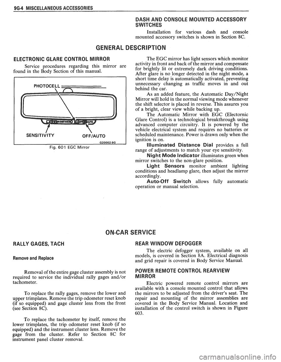
ELECTRONIC GLARE CONTROL MIRROR
Service procedures regarding this mirror are
found in the Body Section of this manual.
Fig. 601 EGC Mirror
The EGC mirror has light sensors which monitor
activity in front and back of the mirror and compensate
for brightly lit or extremely dark driving conditions.
After glare is no longer detected in the night mode, a
short time delay is automatically activated, preventing
unnecessary changing as traffic moves in and out
behind the car.
As an added feature, the Automatic
Day/Night
Mirror will hold in the normal viewing mode whenever
the shift selector is placed in reverse. This assures you
of a bright, clear view while backing up.
The Automatic Mirror with EGC (Electornic
Glare Control) is a technological breakthrough using
advanced computer circuitry. It is powered by the
vehicle electrical system and requires no batteries or
scheduled maintenance. Power is drawn only when the
ignition is on.
Illuminated Distance Dial provides a full
range of adjustments to match your eye sensitivity.
Night Mode Indicator illuminates green when
mirror switches to the non-glare position.
Light Sensors monitor ambient lighting
conditions and
headlamp glare, then adjust the mirror
accordingly.
Auto-Off Switch allows fully automatic
operation or manual selection.
ON-CAR SERVICE
RALLY GAGES, TACH REAR WINDOW DEFOGGER
Remove
and Replace
The electric defogger system, available on all
models, is covered in Section
8A. Electrical diagnosis
and grid repair is covered in Body Service Manual.
Removal of the entire gage cluster assembly is not
POWER RmOTE CONTROL REARVIEW
required to service the individual rally gages and/or MIRROR
tachometer.
Electric powered remote control mirrors are
available with a console mounted control that allows
To replace the rally gages, remove the lower and the
mirrors to be adjusted from the driver's seat. The
upper trimplates. Remove the trip odometer reset knob repair
and mounting of the mirror assemblies are
(if so equipped) and gage cluster lens from the front covered in
the Body Service Manual. Location and
(see Section
8C). installation of the control switch is shown in Figure
603.
To replace the tachometer by itself, remove the
lower trimplates, the trip odometer reset knob (if so
equipped) and the instrument cluster lens. Remove the
gage from the cluster. Refer to Section
8C for
hstrument panel cluster removal.
Page 1680 of 1825
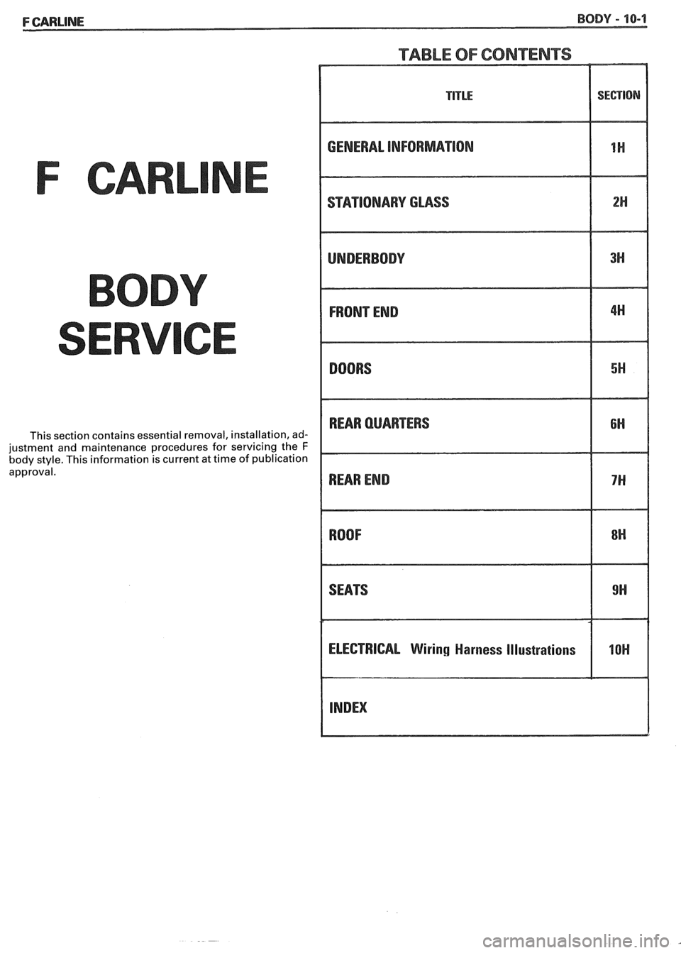
TABLE OF CONTENTS
F CARL
This section contains essential removal, installation, ad-
justment and maintenance procedures for servicing the
F body style. This information is current at time of publication
approval.
GENERAL INFORMATION
STATlONARV GLASS
REAR QUARTERS
ELECTRICAL
Wiring Harness Illustrations
I -IoH I
Page 1683 of 1825
1 H-2 GENERAL INFORMATION - F STYLE
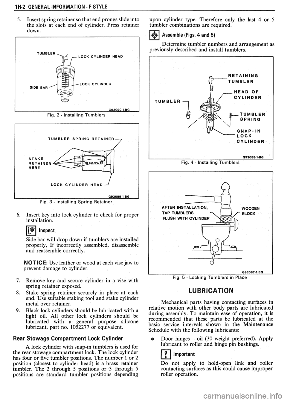
5. Insert spring retainer so that end prongs slide into
upon cylinder type. Therefore only the last 4 or 5
the slots at each end of cylinder. Press retainer
tumbler combinations are required.
down.
TUMBLER \m , LOCK CYLINDER HEAD
SIDE BAR LOCK CYLINDER
Fig.
2 - Installing Tumblers
TUMBLER SPRING RETAINER
LOCK CYLINDER HEAD
Fig.
3 - Installing Spring Retainer
6. Insert key into lock cylinder to check for proper
installation.
Inspect
Side bar will drop down if tumblers are installed
properly, If incorrectly assembled, disassemble
and reassemble correctly.
NOTICE: Use leather or wood at each vise jaw to
prevent damage to cylinder.
7. Remove key and secure cylinder in a vise with
spring retainer exposed.
8. Stake spring retainer securely in place at each
end. Use suitable staking tool and stake cylinder
metal over retainer.
9. Black lock cylinders should be lubricated with a
light oil. All other lock cylinders should be
lubricated with a general purpose silicone
lubricant, part no. 1052277 or equivalent.
Assemble (Figs. 4 and 5)
Determine tumbler numbers and arrangement as
previously described and install tumblers,
TUMBLER
I CYLINDER I
Fig. 4 - Installing Tumblers
AFTER INS WOODEN
TAP TUMBLERS BLOCK
FLUSH
WITH CYLINDER
Fig. 5 - Locking Tumblers in Place
LUBRICATION
Mechanical parts having contacting surfaces in
relative motion with other body parts are lubricated
during assembly. To maintain ease of operation, it is
recommended that these parts be lubricated at the
basic service intervals shown in the Maintenance
Schedule with the following lubricants:
Rear Stowage Compartment Lock Cylinder Door hinges - oil (30 weight preferred). Apply
A lock cylinder with snap-in tumblers is used for lubricant
to roller and hinge pin bushings.
the rear stowage compartment lock. The lock cylinder
Important has four or five tumbler positions. The number 1 or 2
position (closest to cylinder head) is a brass retainer Do
not apply to hold-open link and roller
tumbler. The
2 through 5 positions or 3 through 5 contacting
surfaces as this could cause improper
positions are standard tumbler positions depending roller operation.
Page 1821 of 1825
6- CHASSIS INDEX
Upper Air Outlet Deflectors ...................... 8C-12
Interior Lights ............................................. 8A- 1 17-0
Intermediate Shaft (Steering Column)
.............. 3B5-3
J
Jump Starting .................................................... 6D 1-4
Junction Block
((2238) ................................. 8A-202-2
L
Lamp Monitoring ......................................... 8A- 1 1 1-0
License Plate Lights .............................................. 8B-2
Light Switch
.................................................... 8A- 12-0
Lighting Systems and Horns
...................... Section 8B
General Description ......................................... .8 B- 1
Exterior Lights
............................................ 8B- 1
Horns ....................... .. ................................. 8B-3
On-Car Service
.................................................. 8B-3
Exterior Lights 8B-3
Horns
.............................................................. 8B-9
Replacement Bulb Specifications .................... 8B-10
Lights (Exterior) Electrical Diagnosis
Back-up
...................................................... 8A- 1 12-0
Fog ............................................... 8A- 100.3,10 3.0
Front
Marker/Park/Hazard .................... 8A-110-0
Hazard with Lamp Monitor .................... 8A-103-0
Headlights .................................................. 8A- 100-0
High Level Stop
..................................... 8A-110-0
License .................................................. .8A.110.3, 4
Rear Marker
........................................... .8 A. 1 10.3, 4
Stop ........................................................... 8A-110-1
Tail ......................................................... .8 A. 1 10.3, 4
Tail with Monitor
................ .... ........... 8A- 1 1 1-2
Turn
......................................................... 8A- 1 10-0
Lights (Interior) Electrical
Diagnosis Cargo Compartment
............................. 8A- 1 14- 1
Courtesy
................................................. 8A- 1 14-0
Dome
.................................. .. ...................... 8A- 1 14-0
Glove Box .................................................. 8A- 1 14-0
Lights Dimming
...................................... 8A- 1 17-0
Reading
...................................................... 8A- 1 14-0
Lower Heater Outlet
........................................ 1A-14
Lubrication Fitting Locations .............................. OB-6
M
Maintenance and Lubrication .................... Section OB
Manual Transmission
. 5 Speed 77 mm .... Section 7B
Diagnosis
........... .. ............................................ 7B-2
On-Vehicle Service
.......................................... 7B-3
Repairs
................................... .... .................... 7B- 12
Special Tools
................................................. 7B-20
. Specifications .............................................. 7B 19
Maintenance Items
................................................ OB-2
Master Cylinder
........................................ Section 5A3
General Description
...................................... ..5A 3.2
On-car Sevice
................................................ 5A3-2
Unit Repair ..................................................... .5A 3.2
Master Cylinder Overhaul
......................... .5A 3.2
Master Cylinder Reservoir
......................... .5A 3.3
Metric Fasteners
................................................ OA- 1
Metric-English Conversion Table ..................... .O A. 10
Miscellaneous Accessories
........................ Section 9G
Diagnosis
.......................................................... 9G-2
Dash/Console Mounted Accessory
Switches
.................................................... 9G-4 Electric
Rear Window Defogger
................ 9G-2
Power Remote Control
Rearview
......................... Mirror ...................... .. 9G-2
Rally Gages
................................................. 9G-2
Tachometer
.................................................. 9G-2
..................................... General Description 9G-4
Electric Glare Control Monitor
.................. 9G-4
Electric Rear Window Defogger
................ 9G-2
Power Remote Control
Rearview
Mirror ..................................................... 9G-2
Rally Gages
................................................. 9G-1
Tachometer
................................................. 9G-1
Trip Odometer
............................................ 9G-1
............................................. On-Car Service 9G-4
Power Remote Control Mirror
.................... 9G-4
Rally Gages. Tach
..................................... 9G-4
Rear Window Defogger
.............................. 9G-4
Mirrors..Power ............................................ 8A- 141-0
Automatic
Day/Night ............................. 8A- 143-0
..................................... Defogger. Mirror 8A-61-0
.......................................... Model Identification OA-'
Muffler ................................................................. 6Fi
N
Neutral Start and Back-Up Lamp
Switch
...................................... ..
0
On-Vehicle Service
Air Conditioning
.................................... ... . 1B-20
Automatic Transmission
............................... .7A 1.3
Battery
........................................................ 6D1-5
................................ ......................... Brakes ... 5-7
Bumpers
......................................................... 2B-4
Charging System
.............................. ... ........... 6D3-2
Chassis Sheet Metal
.......................................... 2C-7
Clutch
................................................................ 7C-5
Cranking System
............................................ 6D2-4
Cruise Control ............................................... 9B-6
Disc Brake Caliper Assembly,
3000/3 100 Series .......................................... 5BliC
Disc Brake Caliper Assembly,
3548 Series
................................................... 5B6-3
Drum Brake Assembly .................................... 5C3-1
Engine (V-6) .................................................... 6A2-7
Engine (V-8) ................................................ -6A3-5
Engine Cooling ....................................... .. .... 6B- 14
Front Suspension
........................................... 3C-1
Horns and Lighting System .............................. 8B-3
Ignition System
.............................................. 6D4-5
Instrument Panel, Gages and
Console
.......................................................... 8C-4
Lighting System and Horns
.......................... .... 8B-3
Miscellaneous Accessories
.......................... .... 9G-4
Power Head Assembly
. Tandem
Diaphragm
................................................. 5D-2
Power Steering Gear and Pump
.................... 3B7-3
Propeller Shaft
............................................. 4A-1
.......................... Radio Systems and Antennas 9A-9
Rear Axle
.......................................................... 4B-8
Rear Axle (Borg Warner)
........................... ... 4B 1-7
Steering Linkage ............................................. 3B6-2
........................ Steering Wheels and Columns 3B5-2
Wheel Alignment
......................................... 3A-2
Windshield Wiper
- Washer System ................ 8E-3
Page 1823 of 1825
8- CHASSIS INDEX
Recommended Fluids and Lubricants ................ OB-6
Relay Rod
......................................................... 3B6-2
Remote Mirror Control
...... See Body Service Section
5H.1. 15
Repair Procedures
.......................................... 88-50
S
........................................ Scheduled Maintenance OB- 1
Seats (Power) ....................................... Lumbar Support 8A- 145-0
............................. Sequential Fuel Injection 6E3-C2- 1
Service Engine Soon Light
.................................... 8C-3
Sheet Metal and Grille
................................ Section 2C
......................................... General Description .2 C. 1
........................................... Service Procedures .2 C. 1
................................................................. Hood .2 C. 1
...................................................... Hood Hinge 2C-2
Hood Latch and Cable
...................................... 2C-2
Paint
.............................................. Color Matching 2C-5
................................................ Identification -32-6
Interior Plastic Parts ...................................... 2C-6
................................................ Shock Absorbers 3D-
1
Shoe and Lining Assembly
. Brake
............................................ 3000/3 100 Series 5B1-3
3548 Series ...................................................... 5B6-4
Side Marker Lights
.............................................. 8B-2
........ Speakers See 8A- 150-0 & Body
Manual Section
6H- 1
.................... Spark Plug Gap .. .................. 6E3-13-3
................................ Speaker and Speaker Grille 9A-9
Special Tools
............................................ Air Conditioning 1 B-3 5
Air Conditioning Compressor
................................................. Overhaul 1D1-21
........................ Automatic Transaxle AT-700-R4-64
................................................................ Brakes SF-1
Clutch ................................................................ 7C-8
................................................................ Rear 4B1-20
....................................... Rear (Borg Warner) 4B-20
........................... Driveability and Emissions .6 E. 17
................................................ Engine Cooling 6B- 14
Power Steering Pump
& Gear ...................... 3B7-17
............................................... Propeller Shaft .4 A. 12
Steering Wheels and Columns
.......................... 5-35
Specifications Automatic Transmission Unit
............................................ Repair AT-700-R4-59
..................................................... Battery 6D 1-7
................................................................ Brakes 5F-1
Bumpers
......................................................... 2B-5
Charging System
................ .. ................... 6D3-3
.............................................................. Clutch .7 (2.8
....................................... Cranking System 6D2- 1 1
Driveability and Emissions ............................ 6E-23
................................................ Engine (V-6) ..6A 2.26
Engine (V-8) .................................................. 683-28
........................................ Front Suspension 3C- 10
Power Steering Gear and Pump
.................. 3B7-18 ............................................. Propeller Shaft .4 A. 12 ........................................................ Rear Axle 4B-19 ............................ Rear Axle (Borg Warner) 4B 1- 19
Rear Suspension
.............................................. 3D-9
.......................................... Replacement Bulbs 8Br 10 .............................................. Steering Linkage 3B6-6
Steering Wheels and Columns
...................... 3B5-35
........................................ Wheel Alignments 3A-4
....................................................... Speedometer 8C-2
........................................ Speedometer (Removal) 8C-5
...................................................... Speed Sensors 8C-1
Starter ........................................ Section 6D2. 8A-30-0
............................................. Starter (Circuit) 8A-30-0
Steering Linkage ...................................... Section 3B6
....................................... General Description 3B6-1
........................ Maintenance and Adjustments 3B6-1
................................................ On-Car Service 3B6-2
..................................................... Idler Arm 3B6-4
................................................ Pitman Arm 3B6-5
.................................................... Relay Rod 3B6-3
Tie Rods
...................................................... 3B6-2
.................................................. Specifications 3B6-6
Steering, Suspension, Tires and
Wheels Diagnosis
............................................................. 3-1
Steering Wheels and Columns
............................ 3B5-1
..................................... General Information 3B5- 1
Maintenance and Adjustments
...................... 3B5-'
On-Car Service .............................. .. ........... 3B5
Checking for Accident Damage
.................. 3B5-5
Intermediate Shaft ............... .. .................... 3B5-3
Park Lock Cable .......................................... 3B5-4
Standard Column
............................. Automatic Transaxle 3B5-13
Manual Transaxle ................................. 3B5- 19
Tilt Column
.............................. Automatic Transaxle 3B5-27
.................................. Manual Transaxle 3B5-19
Unit Repair Intermediate Shaft
...................................................... Assembly 3B5-6
................................................. Special Tools 3B5-35
Torque Specifications
.................................... 3B5-35
............................................. Starting System 8A-30-0
........................................ Strut Assembly (Front) 3C-4
.................................... ..... Symbols Chart ... 8A-3-0
T
.......................................................... Tachometer 9G-1
Tail/Stop/Turn Signal/Lights .......................... 8B-2
Temperature Cable
.............................................. 112 A-
Temperature Warning Light ................................ 8C-3
Theft Deterrent (Circuit)
.............................. 8A-133-0
Tie Rods
.............................................................. 3B6-2
Tires and Wheels
........................................ Section 3E
Diagnosis
.................................................. Section 3
General Information
......................................... 3E-1
................................................... Metric Tires 3E-2
....................................... Replacement Tires .31 E-
.................................................... Tire Placard 3E-2
........................................................... Wheels 3E-2
Maintenance and Adjustments
.......................... 3E-2
.......................... Aluminum Wheel Cleaning 3E-9
............................. ......... Inflation of Tires .. 3E-3
........................................ Tire Chain Usage 3E-4
.................................................. Tire Rotation 3E-3
.............................................. Wheel Repair 3E-2
...................................... Wheel Studs/Nuts 3E-3
........................................... Service Operations 3E-4
........................ Aluminum Wheel Cleaning 3E-9
.................................... Balance Precautions 3E-7
............................ Balancing Tire and Wheel 3E-7
.............................................. Compact Spare 3E-6
........................ Correcting Nonuniform Tires 3E-8