1988 PONTIAC FIERO boot
[x] Cancel search: bootPage 334 of 1825
DIRECT TORQUE DRUM BRAKE ASSEMBLY 5C3-7
Install or Connect
See NOTICE on page 5- 1.
1. Position wheel cylinder assembly (28) and hold in
place with wooden block between cylinder and
axle flange.
2. New retainer (19) over wheel cylinder abutement
using a 1-
1/8 inch 12-point socket (32) and socket
extention (31) as shown in figure
6.
3. Inlet tube nut to 17 N-m (13 1b-ft).
4. Bleed wheel cylinder.
BACKING PLATE
Remove or Disconnect
1. Raise
car and suitably support, see Section OA.
2. Brake
components as previously described.
3. Axle shaft, see Section 4B.
4. Parking brake
cable from backing plate
5. Brake pipe from wheel cylinder
6. Backing plate bolts and nuts
7. Anchor
pin nut and anchor pin
Install or Connect
1. Backing plate to axle flange
2. Backing plate to axle flange nuts and bolts to 58
N.m (45 lbs. ft.)
3. Anchor
in and nut to 140 N.m ( 103 Ibs. ft.)
4. Brake
pipe to
wheel cylinder to 15 N.nl (I l Ibs.
ft.)
5. Parking brake cable to backing plate
6. Axle shaft, see section 48
7. Brake
components as previously described
8. Lower car.
9. Bleed brake hydraulic syatcm
10. Adjust brake asscnlbly and parking brakc
UNIT REPAIR
WHEEL
CYLINDER OVERHAUL
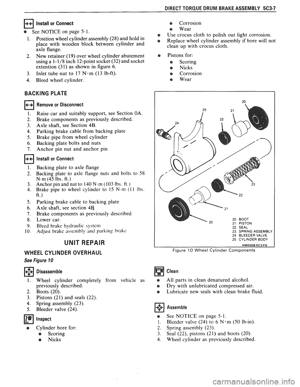
See Figure 10
+++ Disassemble [I]
1. Wheel cylinder completely from vehicle as
previously described.
2. Boots (20).
3. Pistons (21) and seals (22).
4. Spring assembly (23).
5. Bleeder valve (24).
e Cylinder bore for:
e Scoring
e Nicks
e Corrosion
e Wear
e Use crocus cloth to polish out light corrosion.
e Replace wheel cylinder assembly if bore will not
clean up with crocus cloth.
e Pistons for:
e Scoring
e Nicks
e Corrosion
e Wear
22 SEAL 23 SPRING ASSEMBLY 24 BLEEDER VALVE 25 CYLINDER BODY
Figure 10 Wheel Cylinder Components
Clean
e All parts in clean denatured alcohol.
e Dry with unlubricated compressed air.
e Lubricate new seals with clean brake fluid.
Assemble
e See NOTICE on page 5-1.
1. Bleeder valve (24) to 6 N.m (50 lb-in).
2. Spring assembly (23).
3. Seal
(22), pistons (21) and boots (20).
4. Wheel
cylinder as previously described,
Page 336 of 1825
POWER HEAD ASSEMBLY 582-1
SECTION 582
POWER HEAD ASSEMBLY - TANDEM
APHRAGM
CONTENTS
...................... GENERAL DESCRIPTION 5D2-2 Unlocking and Locking Booster ................ 5D2-3
................................. ON-CAR SERVICE 5D2-2 Power Piston Group ................................. 5D2-3
..................................... Booster Assembly 5D2-2 Power Piston Disassembly ......................... 5D2-4
................................. Exterior Components 5D2-2 Gaging Procedure ...................................... 5D2-7
......................................... UNIT REPAIR 5D2-2
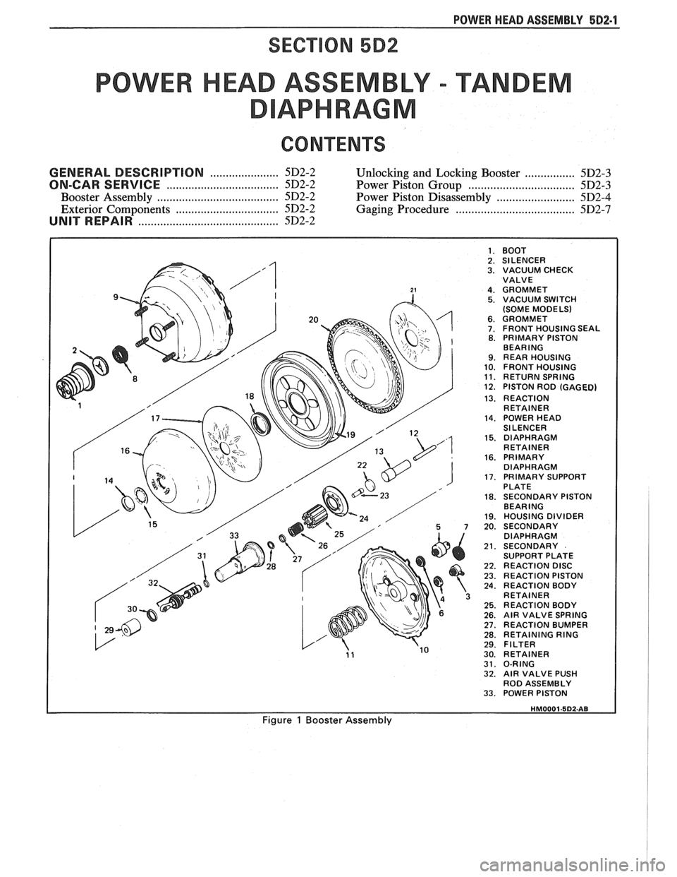
I 1. BOOT I 2. SILENCER 3. VACUUM CHECK
VALVE
4. GROMMET 5. VACUUM SWITCH
(SOME MODELS)
6. GROMMET 7. FRONT HOUSING SEAL 8. PRIMARY PISTON
BEARING
9. REAR HOUSING 10. FRONT HOUSING 11. RETURN SPRING 12. PISTON ROD (GAGED)
13. REACTION
RETAINER
14. POWER HEAD
SILENCER
15. DIAPHRAGM
RETAINER
16. PRIMARY
DIAPHRAGM
17. PRIMARY SUPPORT
PLATE
18. SECONDARY PISTON
BEARING
19. HOUSING DIVIDER 20. SECONDARY
DIAPHRAGM
21. SECONDARY
SUPPORT PLATE
22. REACTION DISC 23. REACTION PISTON 24. REACTION BODY
RETAINER
25. REACTION BODY 26. AIR VALVE SPRING 27. REACTION BUMPER 28. RETAINING RING 29. FILTER 30. RETAINER 31. O-RING 32. AIR VALVE PUSH
ROD ASSEMBLY
33. POWER PISTON
Figure 1 Booster Assembly
Page 337 of 1825
582.2 POWER HEAD ASSEMBLY
GENERAL DESCRIPTION
This booster is a tandem vacuum suspended unit.
In a normal operating mode, with the service brakes in
the released position, the tandem vacuum suspended
booster operates with vacuum on both sides of its
diaphragms. When the brakes are applied, air at
atmospheric pressure is admitted to one side of each
diaphragm to provide the power assist. When the
service brake is released, the atmospheric air is shut off
from the one side of each diaphragm. The air is then
drawn from the booster through the vacuum check
valve to the vacuum source.
important
e Replace all components included in repair kits
used to service this booster.
e Lubricate rubber parts with silicone grease,
provided in kits, to ease assembly.
o Do not use lubricated shop air on brake parts as
damage to rubber parts may result.
o If any hydraulic component is removed or
disconnected, it may be necessary to bleed all or
part of the brake system.
e The torque values specified are for dry,
unlubricated fasteners.
Perform service operations on a clean bench free
from all mineral oil materials.
ON-CAR SERVICE
BOOSTER ASSEMBLY
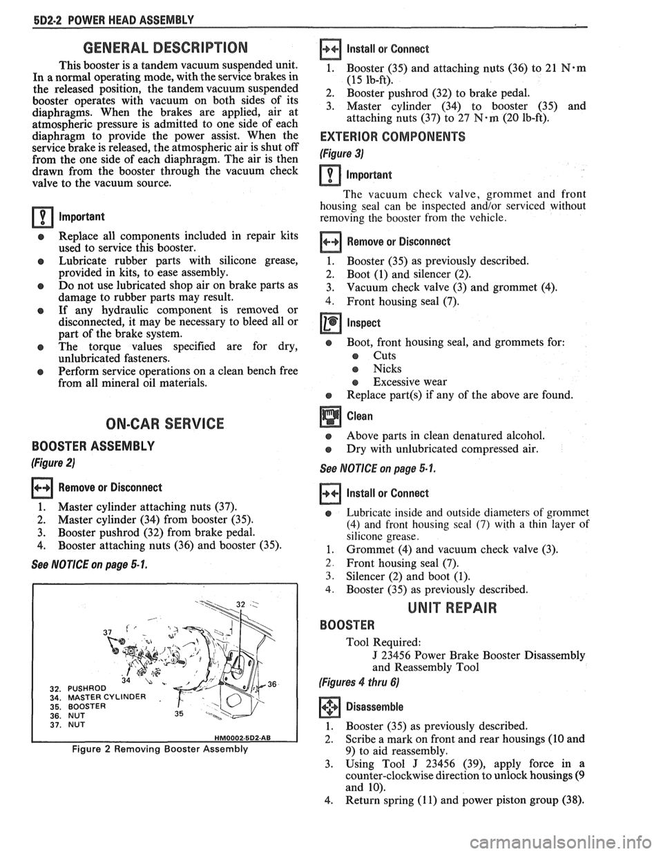
(Figure 2)
Remove or Disconnect
1. Master cylinder attaching nuts (37).
2. Master cylinder (34) from booster (35).
3. Booster pushrod (32) from brake pedal.
4. Booster attaching nuts (36) and booster (35).
See NOTICE on page 5 1.
MASTER CYLINDER
BOOSTER
NUT
BOOSTER
Figure 2 Removing Booster Assembly
Install
or Connect
1, Booster (35) and attaching nuts (36) to 21 N*m
(15 lb-ft).
2. Booster pushrod (32) to brake pedal.
3. Master cylinder (34) to booster (35) and
attaching nuts (37) to
27 N-m (20 lb-ft).
EXTERIOR COMPONENTS
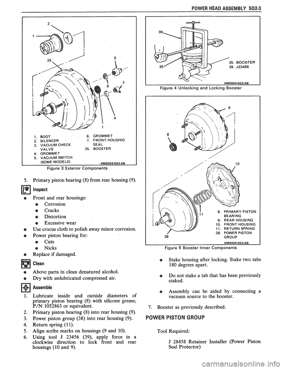
(Figure 3)
Important
The vacuum check valve, grommet and front
housing seal can be inspected and/or serviced without
removing the booster from the vehicle.
Remove or Disconnect
1. Booster (35)
as previously described.
2. Boot (1) and silencer (2).
3. Vacuum check
valve (3) and grommet (4).
4. Front housing seal (7).
Inspect
e Boot, front housing seal, and grommets for:
s Cuts
s Nicks
s Excessive wear
e Replace part(s) if any of the above are found.
Above parts in clean denatured alcohol.
Dry with unlubricated compressed air.
See NOTICE on page 5-1.
Install or Connect
e Lubricate inside and outside diameters of grommet
(4) and front housing seal
(7) with a thin layer of
silicone grease.
1. Grommet (4) and vacuum check valve (3).
2. Front housing seal (7).
3. Silencer (2) and boot (1).
4. Booster (35) as previously described.
UNIT REPAIR
BOOSTER
Tool Required:
J 23456 Power Brake Booster Disassembly
and Reassembly Tool
(Figures 4 thru 6)
Disassemble
1. Booster (35) as previously described.
2. Scribe a mark on front and rear housings (10 and
9) to aid reassembly.
3. Using Tool
J 23456 (39), apply force in a
counter-clockwise direction to unlock housings
(9
and 10).
4. Return spring
(1 1) and power piston group (38).
Page 338 of 1825
POWER HEAD ASSEMBLY 5D2-3
1. BOOT 6. GROMMET 2. SILENCER 7. FRONT HOUSING 3. VACUUM CHECK SEAL VALVE 35. BOOSTER
Figure 3 Exterior Components
5. Primary piston bearing (8) from rear housing (9).
Inspect
e Front and rear housings:
e Corrosion
e Cracks
e Distortion
e Excessive wear
e Use crocus cloth to polish away minor corrosion.
e Power piston bearing for:
e Cuts
e Nicks
e Replace if damaged.
Clean
e Above parts in clean denatured alcohol.
e Dry with unlubricated compressed air.
Assemble
1. Lubricate inside and outside diameters of
primary piston bearing (8) with silicone grease,
P/N 1052863 or equivalent.
2. Primary piston bearing (8) into rear housing (9).
3. Power piston group (38) into rear housing (9).
4. Return spring (1 1).
5. Align scribe marks on housings (9 and 10).
6. Using tool
J 23456 (39), apply force in a
clockwise direction to lock front and rear
housings (10 and 9).
8. PRIMARY PISTON BEARING 9. REAR HOUSING 10. FRONT HOUSING 11. RETURN SPRING 38. POWER PISTON
Figure 5 Booster Inner Components
e Stake housing after locking. Stake two tabs
180 degrees apart.
e Do not stake a tab that has been previously
staked.
e Assembly can be aided by connecting a
vacuum source to the booster.
7. Booster as previously described.
POWER PISTON GROUP
Tool Required:
J 28458 Retainer Installer (Power Piston
Seal Protector)
Page 345 of 1825
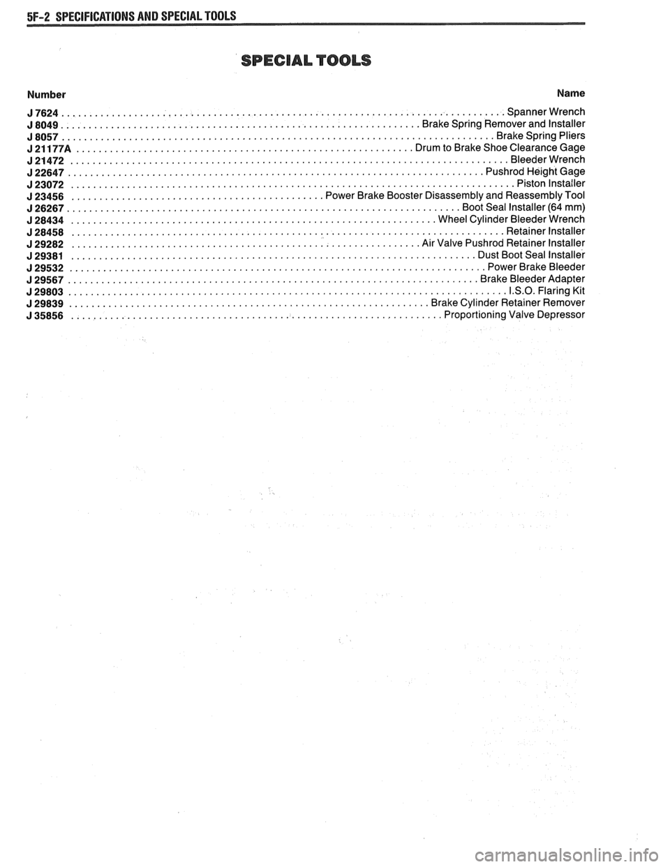
5F-2 SPECIFICATIONS AND SPECIAL TOOLS
SPECIAL TOOLS
Number Name
J7624 ............................................................................... Spannerwrench
................................................................ J 8049 Brake Spring Remover and Installer
J8057 ............................................................................. Brakespringpliers
J21177A ............................................................ DrumtoBrakeShoeClearanceGage
J21472 .............................................................................. Bleederwrench
J22647 .......................................................................... PushrodHei ghtGage
J23072 ............................................................................... Pistonlnstailer
............................................. J 23456 Power Brake Booster Disassembly and Reassembly Tool
J26267 ...................................................................... BootSeallnstaller(64mm)
J28434 ................................................................. WheelCylinderBleederWrench
J28458 ............................................................................. Retainerlnstaller
.............................................................. J 29282 Air Valve Pushrod Retainer Installer
........................................................................ J 29381 Dust Boot Seal Installer
J29532 .......................................................................... PowerBrakeBleeder
J29567 ......................................................................... Br akeBleederAdapter
J29803 .............................................................................. 1.S.O.FlaringKit
................................................................ J 29839 Brake Cylinder Retainer Remover
.................................................................. J 35856 Proportioning Valve Depressor
Page 470 of 1825
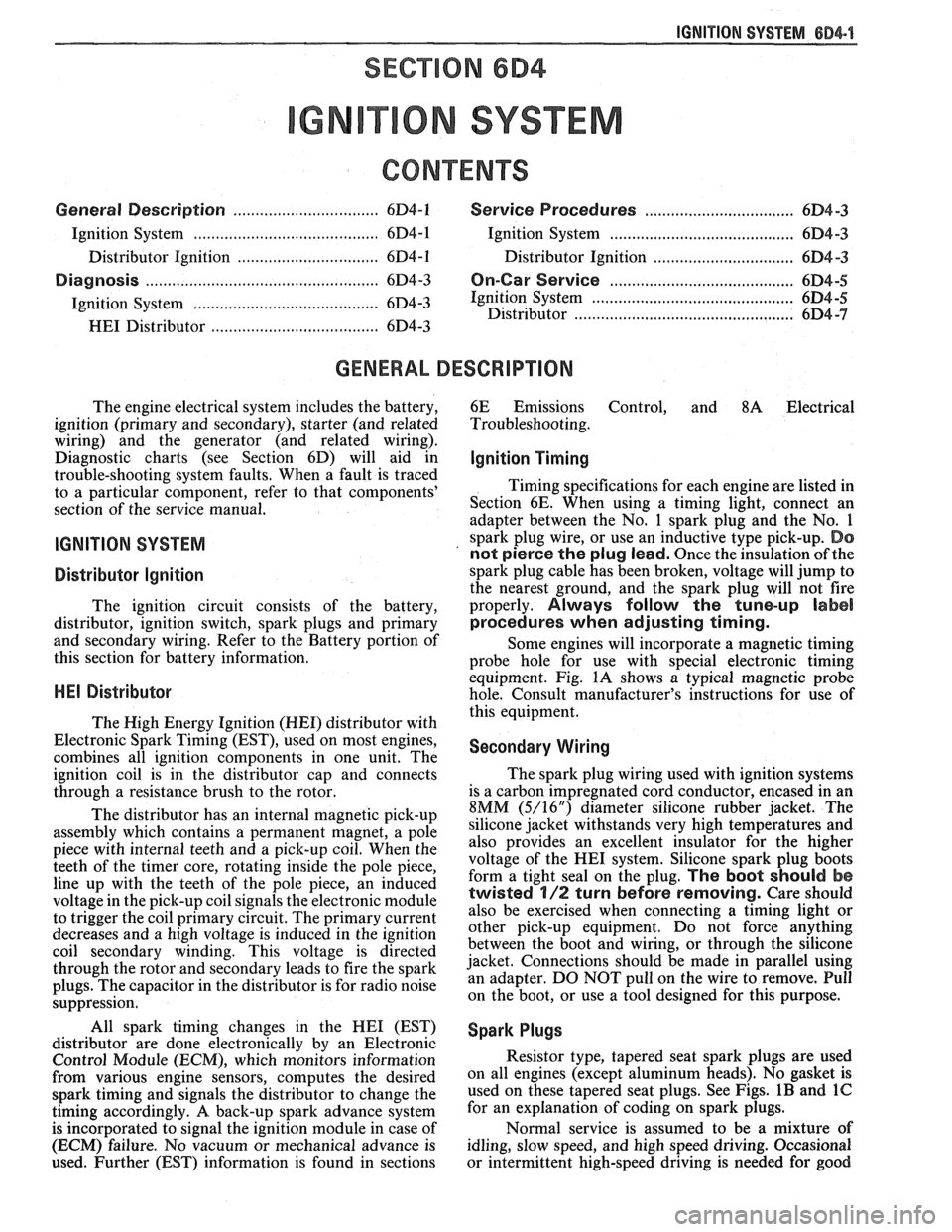
IGNITION SYSTEM 6D4-1
ON SYSTEM
CONTENTS
General Description ............................... 6D4-1 Service Procedures ............................. 6D4-3
Ignition System .......................................... 6D4-1
Ignition System .......................................... 6D4-3
Distributor Ignition ................................ 6D4-1
Distributor Ignition ................................ 6D4 -3
Diannosis .................................................... 6D4-3 On-Car Service ......................................... 6D4-5 -
Ignition System .......................................... (334-3 Ignition System ........................... .. .............. 6D4-5
Distributor ................................................. 6D4 -7 HE1 Distributor .................................... 6D4-3
GENERAL DESCRIPION
The engine electrical system includes the battery,
ignition (primary and secondary), starter (and related
wiring) and the generator (and related wiring).
Diagnostic charts (see Section 6D) will aid in
trouble-shooting system faults. When a fault is traced
to a particular component, refer to that components'
section of the service manual.
IGNITION SYSTEM
Distributor Ignition
The ignition circuit consists of the battery,
distributor, ignition switch, spark plugs and primary
and secondary wiring. Refer to the Battery portion of
this section for battery information.
PIE1 Distributor
The Nigh Energy Ignition (HEI) distributor with
Electronic Spark Timing (EST), used on most engines,
combines all ignition components in one unit. The
ignition coil is in the distributor cap and connects
through a resistance brush to the rotor.
The distributor has an internal magnetic pick-up
assembly which contains a permanent magnet, a pole
piece with internal teeth and a pick-up coil. When the
teeth of the timer core, rotating inside the pole piece,
line up with the teeth of the pole piece, an induced
voltage in the pick-up coil signals the electronic module
to trigger the coil primary circuit. The primary current
decreases and a high voltage is induced in the ignition
coil secondary winding. This voltage is directed
through the rotor and secondary leads to fire the spark
plugs. The capacitor in the distributor is for radio noise
suppression,
All spark timing changes in the
HE1 (EST)
distributor are done electronically by an Electronic
Control Module (ECM), which monitors information
from various engine sensors, computes the desired
spark timing and signals the distributor to change the
timing accordingly.
A back-up spark advance system
is incorporated to signal the ignition module in case of
(ECM) failure. No vacuum or mechanical advance is
used. Further (EST) information is found in sections 6E
Emissions Control, and
8A Electrical
Troubleshooting.
Ignition Timing
Timing specifications for each engine are listed in
Section
6E. When using a timing light, connect an
adapter between the No. 1 spark plug and the No. 1
spark plug wire, or use an inductive type pick-up.
Do
not pierce the plug lead.
Once the insulation of the
spark plug cable has been broken, voltage will jump to
the nearest ground, and the spark plug will not fire
properly.
Always follow the tune-up label
procedures when adjusting timing.
Some engines will incorporate a magnetic timing
probe hole for use with special electronic timing
equipment. Fig.
1A shows a typical magnetic probe
hole. Consult manufacturer's instructions for use of
this equipment.
Secondary Wiring
The spark plug wiring used with ignition systems
is a carbon impregnated cord conductor, encased in an
8MM (5/16") diameter silicone rubber jacket. The
silicone jacket withstands very high temperatures and
also provides an excellent insulator for the higher
voltage of the
HE1 system. Silicone spark plug boots
form a tight seal on the plug.
The boot should be
twisted 1/2 turn before removing. Care should
also be exercised when connecting a timing light or
other pick-up equipment. Do not force anything
between the boot and wiring, or through the silicone
jacket. Connections should be made in parallel using
an adapter. DO NOT pull on the wire to remove. Pull
on the boot, or use a tool designed for this purpose.
Spark Plugs
Resistor type, tapered seat spark plugs are used
on all engines (except aluminum heads). No gasket is
used on these tapered seat plugs. See Figs.
1B and 1C
for an explanation of coding on spark plugs.
Normal service is assumed to be a mixture of
idling, slow speed, and high speed driving. Occasional
or intermittent high-speed driving is needed for good
Page 473 of 1825
684.4 IGNITION SYSTEM
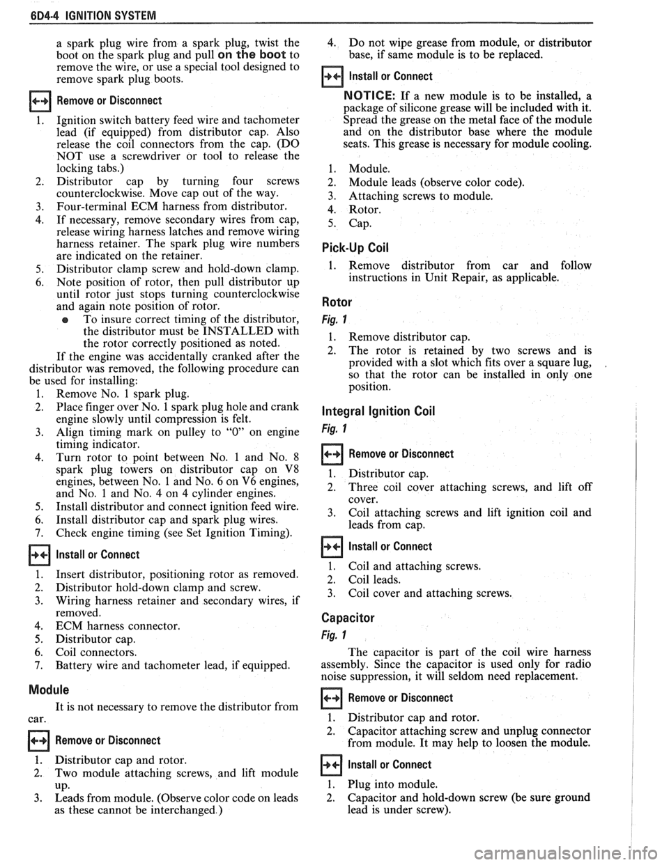
a spark plug wire from a spark plug, twist the 4. Do not wipe grease from module, or distributor
boot on the spark plug and pull
on the boot to base,
if same module is to be replaced.
remove the wire, or use a special tool designed to
remove spark plug boots.
Install or Connect
Remove or Disconnect
1. Ignition switch battery feed wire and tachometer
lead (if equipped) from distributor cap. Also
release the coil connectors from the cap. (DO
NOT use a screwdriver or tool to release the
locking tabs.)
2. Distributor cap by turning four screws
counterclockwise. Move cap out of the way.
3. Four-terminal ECM harness from distributor.
4. If necessary, remove secondary wires from cap,
release wiring harness latches and remove wiring
harness retainer. The spark plug wire numbers
are indicated on the retainer.
5. Distributor clamp screw and hold-down clamp.
6. Note position of rotor, then pull distributor up
until rotor just stops turning counterclockwise
and again note position of rotor.
To insure correct timing of the distributor,
the distributor must be INSTALLED with
the rotor correctly positioned as noted.
If the engine was accidentally cranked after the
distributor was removed, the following procedure can
be used for installing:
1. Remove No. 1 spark plug.
2. Place finger over No. 1 spark plug hole and crank
engine slowly until compression is felt.
3. Align timing mark on pulley to "0" on engine
timing indicator.
4. Turn rotor to point between No. 1 and No. 8
spark plug towers on distributor cap on V8
engines, between No. 1 and No. 6 on V6 engines,
and No.
1 and No. 4 on 4 cylinder engines.
5. Install distributor and connect ignition feed wire.
6. Install distributor cap and spark plug wires.
7. Check engine timing (see Set Ignition Timing).
Install or Connect
1. Insert distributor, positioning rotor as removed.
2. Distributor hold-down clamp and screw.
3. Wiring harness retainer and secondary wires, if
removed.
4. ECM harness connector.
5. Distributor cap.
6. Coil connectors.
7. Battery wire and tachometer lead, if equipped.
Module
It is not necessary to remove the distributor from
car.
Remove or Disconnect
1. Distributor cap and rotor.
2. Two module attaching screws, and lift module
UP. 3. Leads from module. (Observe color code on leads
as these cannot be interchanged.)
NOTICE: If a new module is to be installed, a
package of silicone grease will be included with it.
Spread the grease on the metal face of the module
and on the distributor base where the module
seats. This grease is necessary for module cooling.
1. Module.
2. Module leads (observe color code).
3. Attaching screws to module.
4. Rotor.
5. Cap.
Pick-Up Coil
1. Remove distributor from car and follow
instructions in Unit Repair, as applicable.
Rotor
Fig. 1
1. Remove distributor cap.
2. The rotor is retained by two screws and is
provided with a slot which fits over a square lug,
,
so that the rotor can be installed in only one
position.
Integral Ignition Coil
Fig. I
Remove or Disconnect
1. Distributor cap.
2. Three coil cover attaching screws, and lift off
cover.
3. Coil attaching screws and lift ignition coil and
leads from cap.
Install or Connect I
1. Coil and attaching screws.
2. Coil leads.
3. Coil cover and attaching screws.
Capacitor
Fig. 1
The capacitor is part of the coil wire harness
assembly. Since the capacitor is used only for radio
noise suppression, it will seldom need replacement.
Remove or Disconnect I
1. Distributor cap and rotor.
2. Capacitor attaching screw and unplug connector
from module. It may help to loosen the module.
Install or Connect I
1. Plug into module.
2. Capacitor and hold-down screw (be sure ground
lead is under screw).
Page 474 of 1825
IGNITION SYSTEM 6014.5
3. Rotor and cap. 4. Turn off the engine and remove the timing light.
Reconnect the number one spark plug wire, if
Set Ignition Timing removed.
Spark Plug Wires 1. Refer to the tune-up label located in the engine
compartment. Follow all instructions on the Use
care when removing spark plug wire boots
label. from
spark plugs. Twist the boot
1/2 turn before
removing and pull on the
boot only to remove the
With ignition off, connect the pick-up lead of
timing light to the number one spark plug. Use
a jumper lead between the wire and plug, or an
inductive type pick-up.
DO NOT pierce the wire,
or attempt to insert a wire between the boot and
the wire. Connect the timing light power leads
according to manufacturer's instructions.
Start the engine and aim the timing light at the
timing mark. The line on the balancer or pulley
will line up at the timing mark. If a change is
necessary, loosen the distributor hold-down
clamp bolt at the base of the distributor. While
observing the mark with the timing light, slighty
rotate the distributor until the line indicates the
correct timing. Tighten the hold-down bolt and
re-check the timing. wire.
When replacing plug wires, route the wires
correctly and through the proper retainers. Failure to
route the wires properly can lead to radio ignition noise
and crossfiring of the plugs, or shorting of the leads to
ground.
Special care should be exercised when reinstalling
spark plug boots, to assure that the metal terminal
within the boot is fully seated on the spark plug
terminal and that the boot has not moved on the wire.
If boot to wire movement has occurred, the boot will
give a false visual impression of being fully seated.
A
good check to assure that boots have been properly
assembled is to push sideways on the installed boots.
If they have been correctly installed, a stiff boot, with
only slight looseness, will be noted. If the terminal has
not been properly seated on the spark plug, only the
resistance of the rubber boot will be felt when pushing
sideways.
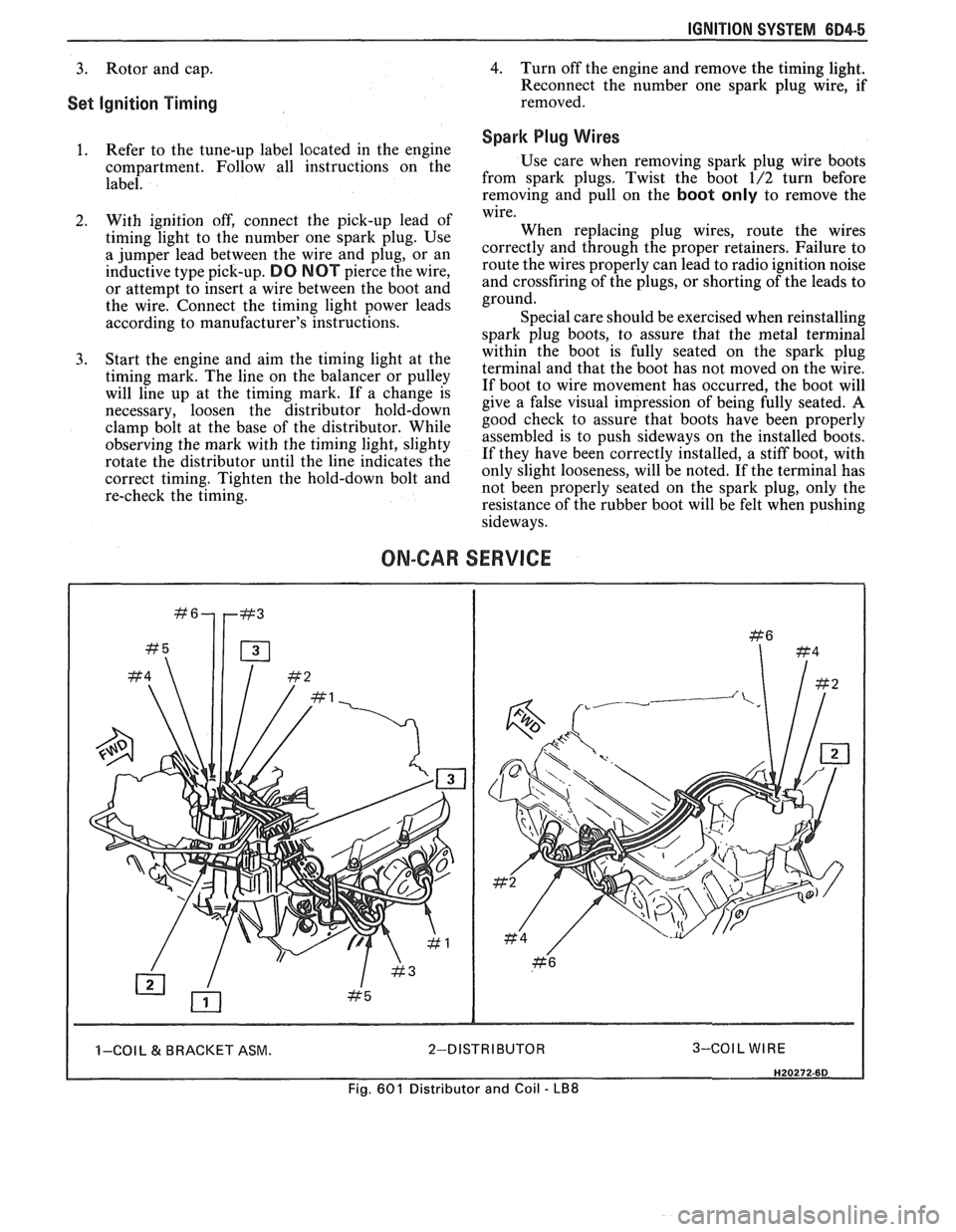
ON-CAR SERVICE
I I -COI L & BRACKET ASM. 2-DISTRIBUTOR 3-COIL WIRE I
Fig. 601 Distributor and Coil - LB8