Page 806 of 1825
DRIVEABILITY AND EMISSIONS 5.OL (VIN F) & 5.7L (VIN 8) 6E3-A-3
- ORN 461
T
TO MAF AND FUEL
PUMP RELAY AND
FAN CONTROL
SWITCH
ALDL CONN
I ENGINE
ENGINE GROUND
GROUND
-
OXYGEN SENSOR
TAN 413
MANIFOLD AIR TAN 472
TEMPERATURE SENSOR
GRY
416
K BLU 417
BLK 452
COOLANT
TEMPERATURE
SENSOR
YEL4lO
PICK-UP COlL
PRIMARY COlL I ..
- WHT
PPWHT
TANJBLK
BLWRED SERIAL
DATA
DIAGNOSTIC TEST
SYSTEM GROUND
SYSTEM GROUND
BACK
SYSTEM GROUND OF
CONNECTOR
OXYGEN SENSOR
SIGNAL
OXYGEN SENSOR
GROUND
24 PIN
A-0 CONNECTOR
MAT SENSOR
SIGNAL
BACK
VIEW OF
CONNECTOR
+ 5V REF.
TPS SIGNAL
5V RETURN
COOLANT TEMP.
SIGNAL
32 PIN C-D
CONNECTOR
EST
REFERENCE
BY-PASS
DISTRIBUTOR GROUND
8s 4240
7-13-87
Page 808 of 1825
DRIVEABILITY AND EMISSIONS 5.OL (VIN F) & 5.7L(VIN 8) 6E3-A-5
MAF SENSOR
POWER RELAY ECM
12v
FUEL
PUMP
RELAY DRIVE
(12W)
SYSTEM GND.
BACK VlEW
OF
CONNECTOR
FUEL PUMP
SIGNAL
24 PIN A-B
SYSTEM GND. CONNECTOR
BACK
VlEW OF
CONNECTOR
32 PIN C-D
CONNECTOR
SYSTEM GND.
ANALOG GROUND
MAF SIGNAL INPUT
BURN-OFF
CONTROL
Figure A-4 - Wiring Diagram - 5.OL (VIN F) & 5.7L (VIN 8) "F" Series (3 of 4)
Page 821 of 1825

6E3-A-18 5.OL (WIN F) & 5.7L(VIN 8) DRIVEABILITY AND EMISSIONS
PRESSURE REGULATOR
COLD START
TUBE ASSEMBLY
FUEL PRESSURE
LINE
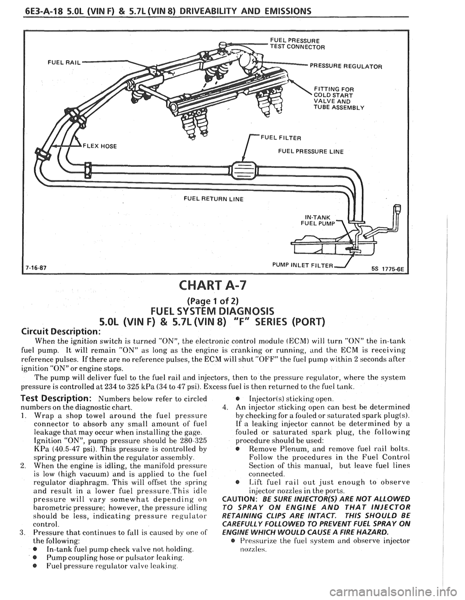
CHART A-7
(Page 1 of 2)
FUEL SYSTEM DIAGNOSIS
5.OL (VIN F) & 5.7L (VIN 8) 'TF'3SERlES (PORT)
Circuit Description:
When the ignition switch is turned "ON", the electronic control module (ECM) will turn "ON" the in-tank
fuel pump. It will remain "ON" as long as the engine is cranking or running, and the
ECM is receiving
reference pulses. If there are no reference pulses, the ECM will shut "OFF" the fuel pump within 2 seconds after
ignition "ON" or engine stops.
The pump will deliver fuel to the fuel rail and injectors, then to the pressure regulator, where the system
pressure is controlled at 234 to 325
kPa (34 to 47 psi). Excess fuel is then returned to the fuel tank.
Test Description: Numbers below refer to circled
numbers on the diagnostic chart.
1. Wrap a shop towel around the fuel pressure
connector to absorb any small amount of fuel
leakage that may occur when installing the gage.
Ignition "ON", pump pressure should be 280-325
KPa (40.5-47 psi). This pressure is controlled by
spring pressure within the regulator
assenlbly
2. When the engine is idling, the manifold pressure
is low (high vacuum) and is applied to the fuel
regulator diaphragm. This will offset
the spring
and result in a lower fuel
pressure.This idle
pressure will vary somewhat depending on
barometric pressure; however, the pressure idling
should be less, indicating pressure regulator
control.
3. Pressure that continues to fall is caused by one of
the following:
In-tank fuel pump check valve not holding.
@ Pump coupling hose or pulsator leaking
@ Fuel pressure regulator valve leaking
Injector(s) sticking open.
4. An
injector sticking open can best be determined
by checking for a fouled or saturated spark
plug(s).
If a leaking injector cannot be determined by a
fouled or saturated spark plug, the following
procedure should be used:
@ Remove Plenum, and remove fuel rail bolts.
Follow the procedures in the Fuel Control
Section of this manual, but leave fuel lines
connected.
s Lift fuel rail out just enough to observe
injector nozzles in the ports.
CAUTION: BE SURE INJECTOR(S) ARE NOT ALLOWED
TO SPRAY ON ENGINE AND THAT INJECTOR
RETAINING CLIPS ARE INTACT.
THIS SHOULD BE
CAREFULLY FOLLOWED TO PREVENT FUEL SPRAY ON
ENGINE WHICH WOULD CAUSE A
FIRE HAZARD.
@ Pressurize the fuel syste~rl and observe injector
nozzles.
Page 822 of 1825
: THIS CHART ASSUMES a CHART m THERE IS NO CODE 54
m PAGE 1.
THE IGNITION MA Y HA
VE TO BE CYCLED "ON"
RESSURE, WITH PUMP RUNNING SHOULD BE MORE
THAN ONCE TO OBTAIN MAXIMUM
(40.5-47 psi) AND HOLD STEADY WHEN PUMP PRESSURE.
ALSO, ITlS NORMAL FOR THE PRESSURE TO DROP SLIGHT1 Y WHEN THE PUMP STOPS.
10 SECONDS.
...... I
@ LEAKING PUMP
@ PLUGGED PUMP INLET FILTER.
RESTRICTED FUEL LINE.
Page 823 of 1825

TEST CONNECTOR PRESSURE REGULATOR
COLD START
VALVE AND
TUBE ASSEMBLY
FUEL PRESSURE
LINE
PUMP INLET FlLTE
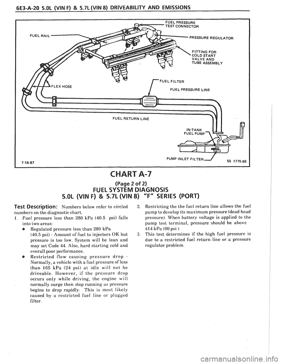
CHART A-7
(Page 2 of 2)
FUEL SYSTEM DIAGNOSIS
5.OL (VIN F) & 5.7L (VIN 8) "F" SERIES (PORT)
Test Description: Numbers below refer to circled
numbers on the diagnostic chart.
1. Fuel pressure less than 280 kPa (40.5 psi) falls
into two areas:
Regulated pressure less than
280 kPa
(40.5 psi) - Amount of fuel to injectors OK but
pressure is too low. System will be lean and
may set Code
44. Also, hard starting cold and
overall poor performance.
@ Restricted flow causing pressure drop -
Normally, a vehicle with a fuel pressure of less
than
165 kPa (24 psi) at idle will not be
driveable. However, if the pressure drop
occurs only while driving, the engine will
normally surge then stop running
as pressure
begins to drop rapidly. This is most likely
caused by
a restricted fuel line or plugged
filter.
2. Restricting the the fuel return line allows the fuel
pump to develop its maximum pressure (dead head
pressure). When battery voltage is applied to the
pump
tesl terminal, pressure should be above
414 kPa (60 psi ).
3. This test determines if the high fuel pressure is
due to
a restricted fuel return line or a pressure
regulator problem.
Page 824 of 1825
DRIVEABILITY AND EMISSIONS 5.0L (VIN F) & 5.7L (VIN 8) 6E3-A-21
NOTICE: THE FUEL SYSTEM IS UNDER PRESSURE. TO AVOID FUEL SPILLAGE,
REFER TO FIELD SERVICE PROCEDURES IN SECTION
"C2" FOR TESTING
OR MAKING REPAIRS REQUIRING DISASSEMBLY OF FUEL LINES OR
.m ...... -
SE TO PRESSURE
@ BLOCK FUEL RETURN LINE.
@ APPLY 12 VOLTS TO FUEL PUMP RELAY
HARNESS TERMINAL "A" OR TO THE
FAULTY IN-TANK
r FUELPUMP
@ COUPLING HOSE OR
Page 845 of 1825

6E3-A-42 S.OL (VIN F) & 5.7L (VIN 8) DRIVEABILITY AND EMISSIONS
SYSTEM GND
SYSTEM GND
SYSTEM GND
ANALOG GND
BURN-OFF CONTROL CKT
-
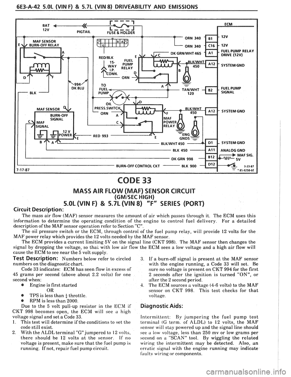
CODE 33
MASS AIR FLOW (MAF) SENSOR CIRCUIT
(GMISEC HIGH)
5.OL (VIN F) & 5.7L (VIN 8) ""FY"IES (PORT)
Circuit Description:
The mass air flow (MAF) sensor measures the amount of air which passes through it. The ECM uses this
information to determine the operating condition of the engine to control fuel delivery.
For
a detailed
description of the MAF sensor operation refer to Section
"C".
The oil pressure switch or the ECM, through control of the fuel pump relay, will provide 12 volts for the
MAF power relay which provides the
12 volts needed by the MAF sensor.
The ECM provides
a current limiting 5V on the signal line (CKT 998). The MAF sensor then changes the
signal by dropping the voltage, so thai with low air flow the ECM sees
a low voltage and a high air flow will
cause the ECM to see near the
5 volt supply.
Test Description: Numbers below refer to circled 3. If a burn-off signal is present at the MAF sensor
numbers on the diagnostic chart.
with the engine running, a Code
33 will set. Be
Code
33 indicates: ECM has seen flow in excess of
sure no voltage is present on CKT 994 for the first
45 grams per second (above about 2.2 volts) for one 2 seconds after the ignition is turned "ON", or
second when: after the
2 second period.
@ Engine is first started 4. The ECM sources a voltage (4-6 volts) to the MAF
OR sensor on CKT 998. This test checks for that
@ TPS is less than 4 throttle. voltage. @ RPM is less than 2000.
Due to the 5 volt pull-up resistor in the ECM if Diagnostic Aids:
CKT 998 becomes open, the ECM will see a high
voltage signal and set
a Code 33. Intermittent:
By jumpering the fuel pump test
1. This test will determine if the conditions to set the terminal (G term, of ALDL) to 12 volts, the MAF
code still exist. sensor will stay powered up and the signal line should
2. With the ALDL terminal "G" jumpered to 12 volts,
see a low voltage, less than 250 mv or low grams per
there should be
12 volts at the sensor. If no second on a "SCAN" tool. By wiggling the related
voltage is present, make sure that the fuel pump
is wiring the intermittent may be detected. Also, an
running.
If not, repair fuel pump circuit. erratic signal with the engine running may indicate
fili~ltv wirinq or components.
Page 847 of 1825

6E3-A-44 5.0b (VIN F) & 5.7L (VIN 8) DRIVEABILITY AND EMISSIONS
SYSTEM GND
SYSTEM GND
BLUNVHT 450 SYSTEM GND
BURN-OFF CONTROL CUT
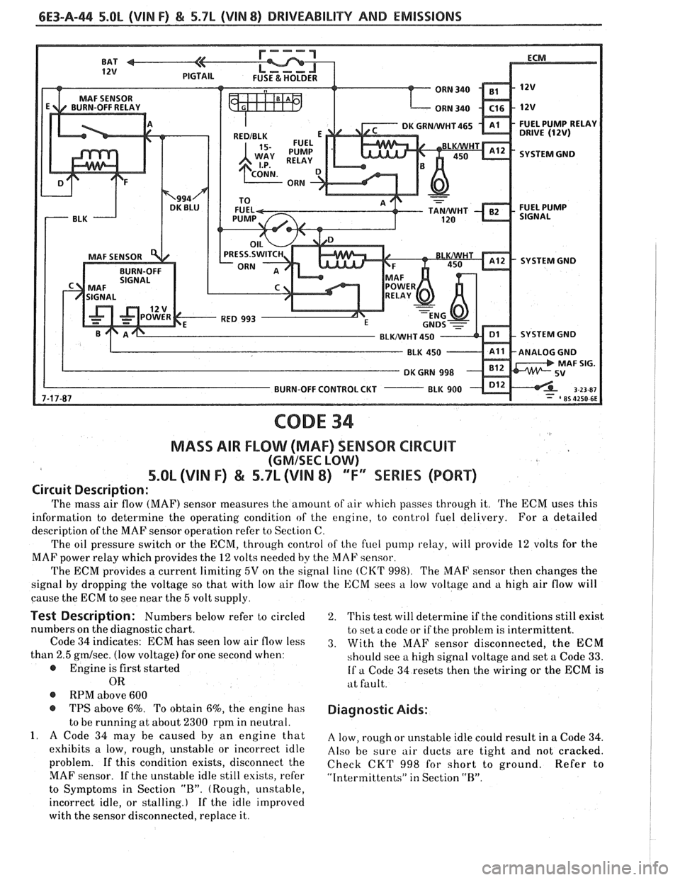
CODE 34
MASS AIR FLOW (MAF) SENSOR CIRCUIT
(GMISEC LOW)
5.OL (VIN F) & 5.7L (\/IN 8) "F"" SERIES (PORT)
Circuit Description:
The mass air flow (MAF) sensor measures the amount of air which passes through it. The ECM uses this
information to determine the operating condition of the engine, to control fuel delivery. For a detailed
description of the MAF sensor operation refer to Section C.
The oil pressure switch or the ECM, through control
of the fuel pump relay, will provide 12 volts for the
MAF power relay which provides the
12 volts needed by the MAF sensor.
The ECM provides a current limiting
5V on the signal line (CKT 998). The MAF sensor then changes the
signal by dropping the voltage so that with low air flow the ECM sees
a low voltage and a high air flow will
cause the ECM to see near the
5 volt supply.
Test Description: Numbers below refer to circled
numbers on the diagnostic chart.
Code
34 indicates: ECM has seen low air flow less
than
2.5 gmlsec. (low voltage) for one second when:
@ Engine is first started
OR
@ RPM above 600
@ TPS above 6%. To obtain 6%, the engine has
to be running at about
2300 rpm in neutral.
1. A Code 34 may be caused by an engine that
exhibits a low, rough, unstable or incorrect idle
problem. If this condition exists, disconnect the
MAF sensor. If the unstable idle still esists, refer
to Symptoms in Section
"R". (Rough, unstable,
incorrect idle, or stalling.) If the idle improved
with the sensor disconnected, replace it.
2. This test will determine if the conditions still exist
to set a code or if the problem is intermittent.
3. With the MAF sensor disconnected, the ECM
should see a high signal voltage and set a Code
33.
If a Code 34 resets then the wiring or the ECM is
at fault.
Diagnostic Aids:
A low, rough or unstable idle could result in a Code 34.
Also be sure air ducts are tight and not cracked.
Check CKT
998 for short to ground. Refer to
"Intermittents" in Section "R".