1988 PONTIAC FIERO fuel pump
[x] Cancel search: fuel pumpPage 892 of 1825
DRIVEABILITY AND EMISSIONS 5.OL (VIN F) & 5.7L (VIN 8) 6E3-C2-5
Fuel Pump Electrical Circuit
When the ignition is first turned "ON", without
the engine running, the ECM will turn the fuel pump
relay "ON" for two seconds.
This builds up the fuel
pressure quickly. If the engine is not started within
two seconds, the ECM will shut the fuel pump "OFF"
and wait until the engine is cranking. As soon as the
engine is cranked, the ECM will turn the relay "ON"
and run the fuel pump.
As
a backup system to the fuel pump relay, the
fuel pump can also be turned "ON" by the oil pressure
switch. The oil pressure switch is a normally open
switch which closes when oil pressure reaches about
28
kPa (4 psi). If the fuel pump relay fails, the oil
pressure switch will close, and run the fuel pump.
An inoperative fuel pump relay can result in long
cranking times, particularly if the engine is cold but
should result in
a Code 54.
An inoperative fuel pump would cause a no start
condition. A fuel pump which does not provide enough
pressure can result in poor performance.
DIAGNOSIS
FUEL CONTROL SYSTEM
Some failures of this system will result in an
"Engine Cranks But Won't Run". If
this condition
exists see CHART A-3. This chart will determine if
the problem is caused by the ignition system, ECM, or
fuel pump circuit. If
it's determined to be a fuel
problem CHART A-7 will be used. This includes the
injectors, pressure regulator, fuel pump, and fuel
pump relay. The fuel system wiring schematic is
covered on the facing page of Code CHART 54.
If a malfunction occurs in the fuel control system,
it usually results in either a rich or
a lean exhaust
condition. This condition is sensed by the oxygen
sensor and the ECM will change the fuel calculation
(injector pulse width) based on the
O2 sensor reading.
The change
made to the fuel calculation will be
indicated by a change in the block learn values, which
can be monitored by a "Scan" tool.
The normal block
learn values are around 128, and if the
O2 sensor is
sensing a lean condition, the EC
M will add fuel which
will result in a block learn value above 128.
If the O2
sensor is sensing a rich exhaust the ECM will reduce
fuel to the engine and this will result in block learn
values below 128. Some variations in block
learn
values are normal because all engines are not exactly
the same. However, if the block learn values are
+ 10
counts from 128 a system problem exists. If the block
learn values are greater than 138 see Code 44, for
items which can cause a lean system.
If the block learn values are less than 118 see Code
45 for items which can cause the system to run rich. If
a driveability symptom exists, refer to the
particular symptom in Section
"B" for additional
items to check.
IDLE AIR CONTROL VALVE
AUScan" tool will read IAC position in steps (counts).
"0" steps indicates the ECM is commanding the IAC to
be driven all the way in, to a fully seated position, and
this is usually caused by a vacuum leak. The higher
the number of counts the more air being allowed to
pass the IAC valve. CHART C-2C can be used to
diagnosis the IAC valve. Also refer to "Rough,
Unstable, or Incorrect Idle, Stalling" in symptoms,
Section "B" for other possibilities for the cause
of idle
problems.
FUEL SYSTEM PRESSURE TEST
A fuel system pressure test is part of several of the
diagnostic charts and symptom checks. To perform
this test, use the procedure in CHART A-7.
ON-CAR SERVICE
PORT FUEL INJECTION COMPONENTS
CAUTION:
Before servicing an injector, fuel
rail, or pressure regulator,
it is
necessary to relieve the pressure in
the fuel system, to minimize the
risk of fire and personal injury.
(See "Fuel Pressure Relief
Procedure" below). To reduce the
chance of personal injury, cover
the fuel line with
a shop cloth to
collect the fuel, and then place the
cloth in an approved container.
FUEL PRESSURE RELIEF PROCEDURE
1. Connect fuel gage J 34730-1 or equivalent to fuel
pressure valve. Wrap a shop towel around fitting
while connecting gage to avoid spillage.
2. Install bleed hose into an approved container and
open valve to bleed system pressure.
Plenum
(Figure
C2-6)
Remove or Disconnect
1. Negative battery cable.
2. Throttle, 'F.V., and cruise control cable.
3. Cable retaining bracket.
4.
'I'hrottle body retaining bolts (4).
5. 'L'l'S and IAC valve electrical connectors.
6. Vacuum hoses.
Page 896 of 1825
DRIVEABILITY AND EMISSIONS 5.OL (VIN F) & 5.7L (VIN 8) 6E3-CZ-9
Cold start valve (100) onto tube and body
assembly
.
Screw in until valve bottoms. then back off
until hole in mounting lug on valve will be
aligned properly with hole in fuel rail when
mounted
.
@ Bend tang over cold start valve to lock it in
position
.
Clean
@ Areas around valve and connection with AC
Delco X-30A or equivalent
.
Install or Connect
1 . Cold start (100) valve in intake manifold .
2 . Cold start valve retaining bolt .
Tighten
@ Retaining bolt to 27 Nwm (20 ft . lbs.). .
3 . PVC hose .
4 . Tube and body assembly (101) at fitting on fuel
rail
.
Tighten
@ Nut on fitting to 27 N-m (20 ft . lbs.).
6 . Brake booster line .
6 . Electrical connector on cold start valve (100)
7 . Negative battery cable .
Inspect
@ Energize fuel pump and inspect for leaks .
8 . Intake manifold plenum. per previous
instructions
.
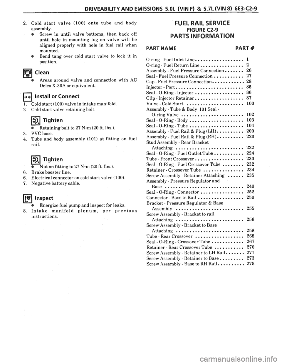
FUEL RAIL SERVICE
FIGURE CZ-9
PARTS INFORMAION
PART NAME PART #
. .................. O-ring Fuel Inlet Line 1
. ................ O-ring Fuel Return Line 2
Assembly
. Fuel Pressure Connection ....... 26
Seal
. Fuel Pressure Connection ........... 27
Cap
. Fuel Pressure Connection ............ 28
Injector
. Port ......................... 85
. . .................. Seal 0-Ring Injector 86
. .................. Clip Injector Retainer 87
. ..................... Valve Cold Start 100
Assembly
. Tube & Body 101 Seal .
....................... O-ring Valve 102
. . .................... Seal 0-Ring Body 103
. . .................... Seal 0-Ring Tube 104
. .......... Assembly Fuel Rail & Plug (LH) 200
. .......... Assembly Fuel Rail & Plug (RH) 220
Stud Assembly
. Rear Bracket
......................... Attaching 222
Seal
. 0-Ring . Fuel Outlet Tube ........... 224
. ................. Tube Front Crossover 230
. . ........ Seal 0-Ring Fuel Crossover Tube 232
. .*............. Retainer Crossover Tube 234
...... . Screw Assembly Retainer Attaching 235
Assembly
. Pressure Regulator and
............................. Base 240
. ................ . Seal 0-Ring Connector 252
. ................. Connector Base to Rail 250
Bracket
. Pressure Regulator & Base
......................... Assembly 255
Screw Assembly
. Bracket to rail
......................... Attaching 256
Screw Assetnhly
. Bracket to Base
......................... Attaching 258
. .................. Tube Rear Crossover 265
. . ............ Seal 0-Ring Crossover Tube 267
........... . Retainer Rear Crossover Tube 270
....... . Screw Assembly Retainer to LH Rail 271
......... . Screw Assembly Retainer to Base 273
.......... . Screw Assembly Base to RH Rail 275
Page 897 of 1825
6E3-C2-"l s5.OL (VIN F) & 5.7b (VIN 8) DRIVEABILITY AND EMISSIONS
FUEL RAIL
26 FUEL PRESSURE CONNECTION ASSEMBLY
27 DEAL - FUEL PRESSURE CONNECTION ASSEMBLY
28 CAP -FUEL PRESSURE CONNECTION ASSEMBLY
06 85 84 5S 1509-6E
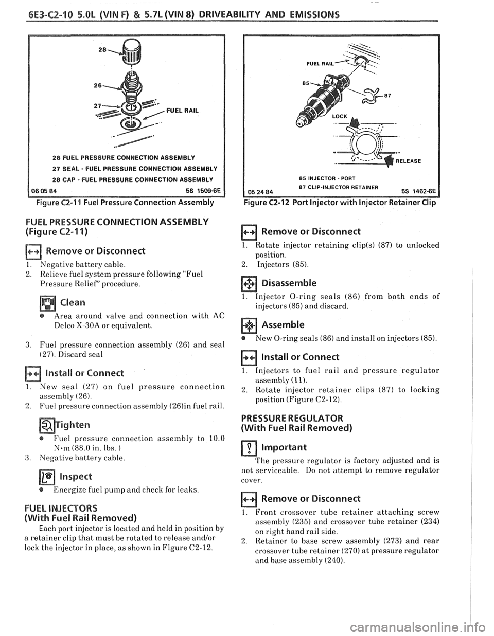
Figure
C2-'11 Fuel Pressure Connection Assembly
FUEL PRESSURE CONNECTION ASSEMBLY
(Figure
CZ-'I I)
Remove or Disconnect
1. Negative battery cable.
2. Relieve fuel system pressure following "Fuel
Pressure Relief' procedure.
a Clean
@ Area around valve and connection with AC
Delco X-30A or equivalent.
3. Fuel pressure connection assembly (26) and seal
(27). Discard seal
Install or Connect
I. New seal (27) on fuel pressure connection
assembly
(26).
2. Fuel pressure connection assembly (26)in fuel rail.
- @ Fuel pressure connection assembly to 10.0
Norn (88.0 in. Ibs.
3. Negative battery cable.
inspect
@ Energize fuel pump and check for leaks.
FUEL INJECTORS
(With Fuel Wail Removed)
Each port injector is located and held in position by
a retainer clip that must be rotated to release
and/or
lock the injector in place, as shown in Figure (22-12.
FUEL RAIL
I 85 INJECTOR - PORT I
Figure CZ-12 Port Injector with Injector Retainer Clip
a Remove or Disconnect
1. Rotate injector retaining clip(s) (87) to unlocked
position.
2. Injectors (85).
+$ Disassemble
1. Injector O-ring seals (86) from both ends of
injectors
(85) and discard.
Assemble
@ New O-ring seals (86) and install on injectors (85).
Install or Connect
1. Injectors
to fuel rail and pressure regulator
assembly
(1 1).
2. Rotate
injector retainer clips (87) to loclring
position (Figure C2-12).
PRESSURE REGULATOR
(With Fuel Rail Removed)
Important
The pressure regulator is factory adjusted and is
not serviceable. Do not attempt to remove regulator
cover.
Remove or Disconnect
1. Front crossover tube retainer attaching screw
assembly
(235) and crossover tube retainer (234)
on right hand rail side.
2. Retainer to base screw assembly (273)
and rear
crossover tube retainer
(270) at pressure regulator
and base assembly (240).
Page 903 of 1825
6E3-CZ-16 5.OL (VIN F) & 5.7L(VIN 8) DRIVEABILITY AND EMISSIONS
Tighten
- @ Screw assemblies to 3.0 Nem (27.0 in. lbs.).
4. IAC valve assembly (70). (See "Idle Air Control
Valve and Gasket" instructions).
NOTICE: Before installing the IAC valve assembly,
the position of its pintle
MUST be checked.
If pintle is extended too far, damage to the
assembly may occur. (See
"Idle Air
Control Valve and Gasket" instructions.)
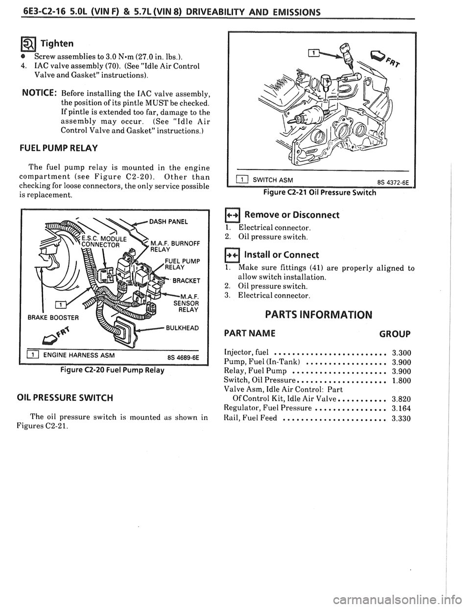
FUEL PUMP RELAY
The fuel pump relay is mounted in the engine
compartment (see Figure
C2-20). Other than
checking for loose connectors, the only service possible
is replacement.
BRAKE BOOSTER
Figure C2-20 Fuel Pump Relay
OIL PRESSURE SWITCH
The oil pressure switch is mounted as shown in
Figures C2-2
1.
Figure C2-21 Oil Pressure Switch
a Remove or Disconnect
I. Electrical connector.
2. Oil pressure switch.
Install or Connect
1. Make sure fittings (41) are properly aligned to
allow switch installation.
2. Oil pressure switch.
3. Electrical connector.
PARTS INFORMATION
PART NAME GROUP
Injector, fuel ......................... 3.300
Pump, Fuel (In-Tank)
.................. 3.900
Relay, Fuel Pump
..................... 3.900
Switch, Oil Pressure,
................... 1.800
Valve Asm, Idle Air Control: Part
Of Control Kit, Idle Air Valve. .......... 3.820
Regulator, Fuel Pressure
................ 3.164
Itail, Fuel Feed ....................... 3.330
Page 905 of 1825
6E3-CZ-18 5.OL (VIN F) & 5.7L(VIN 8) DRIVEABILITY AND EMISSIONS
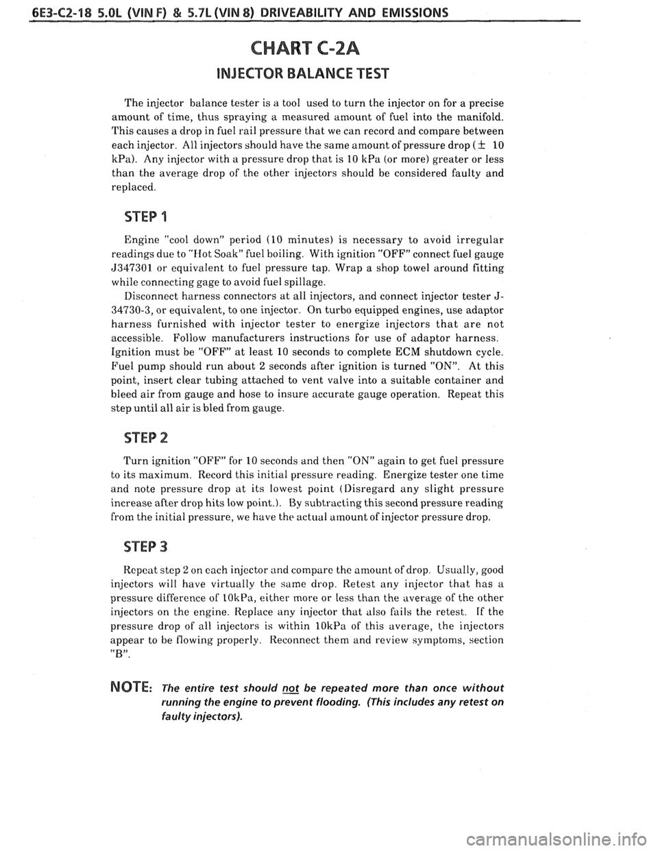
CHART C-2A
INJECWR BALANCE TEST
The injector balance tester is a tool used to turn the injector on for a precise
amount of time, thus spraying
a measured amount of fuel into the manifold.
This causes a drop in fuel rail pressure that we can record and compare between
each injector. All injectors should have the same amount of pressure drop
( f 10
kPa). Any injector with a pressure drop that is 10 kPa (or more) greater or less
than the average drop of the other injectors should be considered faulty and
replaced.
STEP 1
Engine "cool down" period (10 minutes) is necessary to avoid irregular
readings due to "Hot Soak" fuel boiling. With ignition "OFF" connect fuel gauge
5347301 or equivalent to fuel pressure tap. Wrap a shop towel around fitting
while connecting gage to avoid fuel spillage.
Disconnect harness connectors at all injectors, and connect injector tester
J-
34730-3, or equivalent, to one injector. On turbo equipped engines, use adaptor
harness furnished with injector tester to energize injectors that are not
accessible. Follow manufacturers instructions for use of adaptor harness.
Ignition must be "OFF" at least 10 seconds to complete
ECM shutdown cycle.
Fuel pump should run about
2 seconds after ignition is turned "ON". At this
point, insert clear tubing attached to vent valve into a suitable container and
bleed air from gauge and hose to insure accurate gauge operation. Repeat this
step until all air is bled from gauge.
Turn ignition
"OFF" for 10 seconds and then "ON" again to get fuel pressure
to its maximum. Record this initial pressure reading. Energize tester one time
and note pressure drop at its lowest point (Disregard any slight pressure
increase after drop hits low point.). By subtracting this second pressure reading
from the initial pressure, we have
the actual amount of injector pressure drop.
STEP 3
Rcpcat stcp 2 on each injector and compare the amount of drop. Usually, good
injectors will have virtually the same drop. Retest any injector that has a
pressure difference of
LOkPa, either more or less than the average of the other
injectors on the engine. Replace any injector that also fails the retest.
If the
pressure drop of all injectors is within
lOkPa of this average, the injectors
appear to be flowing properly. Reconnect them and review symptoms, section
"B".
NOTE: The entire test should not be repeated more than once without
running the engine to prevent flooding. (This includes any retest on
faulty injectors).
Page 911 of 1825
6E3-C3-2 5.OL (VIN F) & 5.7L (WIN 8) DRIVEABILITY AND EMISSIONS
The ECM turns "ON" the solenoid valve and allows
purge when:
@ Above a specified road speed.
r Engine is warm
@ After the engine has been running a specified
time.
@ Above a specified throttle opening.
This
is an ECM feedback system that increases
purge until the ECM senses a rich condition from the
O2 sensor. The purge is then regulated until the ECM
no longer receives
a rich signal from the O2 sensor.
This system uses an in-tank pressure control valve to
control the flow of vapors from the fuel tank to the
canister.
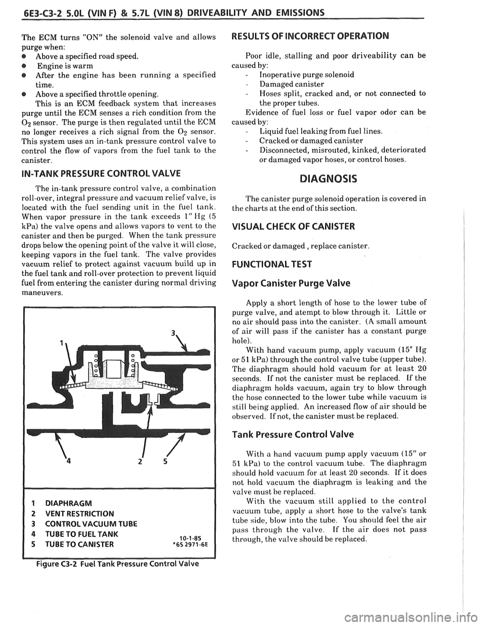
IN-TANK PRESSURE CONTROL VALVE
The in-tank pressure control valve, a combination
roll-over, integral pressure and vacuum relief valve, is
located with the fuel sending unit in the fuel tank.
When vapor pressure in the tank exceeds
1" Hg (5
kPa) the valve opens and allows vapors to vent to the
canister and then be purged. When the tank pressure
drops below the opening point of the valve it will close,
keeping vapors in the fuel tank. The valve provides
vacuum relief to protect against vacuum build up in
the fuel tank and roll-over protection to prevent liquid
fuel from entering the canister during normal driving
maneuvers.
1 DIAPHRAGM
2 VENT RESTRICTION
3 CONTROL VACUUM TUBE
4 TUBE TO FUEL TANK 10-1-85 5 TUBE TO CANISTER *6s 2971-6~
RESULTS OF INCORRECT OPERATION
Poor idle, stalling and poor driveability can be
caused by:
- Inoperative purge solenoid
- Damaged canister
- Hoses split, cracked and, or not connected to
the proper tubes.
Evidence of fuel loss or fuel vapor odor can be
caused by:
- Liquid fuel leaking from fuel lines.
- Cracked or damaged canister
- Disconnected, misrouted, kinked, deteriorated
or damaged vapor hoses, or control hoses.
DIAGNOSIS
The canister purge solenoid operation is covered in
the charts at the end of this section.
VISUAL CHECK OF CANISTER
Cracked or damaged, replace canister.
FUNCTIONAL TEST
Vapor Canister Purge Valve
Apply a short length of hose to the lower tube of
purge valve, and atempt to blow through it. Little or
no air should pass into the canister.
(A small amount
of air will pass if the canister has a constant purge
hole). With hand vacuum pump, apply vacuum
(15" Hg
or 51 kPa) through the control valve tube (upper tube).
The diaphragm should hold vacuum for at least
20
seconds. If not the canister must be replaced. If the
diaphragm holds vacuum, again try to blow through
the hose connected to the lower tube while vacuum is
still being applied. An increased flow of air should be
observed. If not, the canister must be replaced.
Tank Pressure Control Valve
With a hand vacuum pump apply vacuum (15" or
51 kPa) to the control vacuum tube. The diaphragm
should hold vacuum for at least
20 seconds. If it does
not hold vacuum the diaphragm is leaking and the
valve must be replaced.
With the vacuum still applied to the control
vacuum tube, apply a short hose to the valve's tank
tube side, blow into the tube. You should feel the air
pass through the valve. If the air does not pass
through, the valve should be replaced.
Figure C3-2 Fuel Tank Pressure Control Valve
Page 928 of 1825
DRIVEABILITY AND EMISSIONS 5.OL (VIN F) & 5.7L (VIN 8) 6E3-C6-1
SECTION C6
AIR INJECTION REACTION (A.I.R.) SYSEEM
CONTENTS
GENERAL DESCRIPTION ............... C6-1
PURPOSE ....................... C6-1
OPERATION. ..................... C6-1
AIR CONTROL PEDES VALVE ......... C6-1
.... RESULTS OF INCORRECT OPERATION C6-2
DIAGNOSIS
........................ C6-2
OPERATIONAL CHECKS ............. C6-2
Air Pump ...................... C6-2
Hoses and Pipes ................. C6-3
GENERAL DESCRIPTION
PURPOSE
The A.I.R. system helps reduce hydrocarbon (HC),
carbon monoxide (CO), and oxides of nitrogen (NO,)
exhaust emissions. It also heats up the catalytic
converter quickly on engine start-up so conversion of
exhaust gases can occur sooner.
A dual bed converter is used. It consists of a three
way catalyst (which controls all three emissions) in
series with
a two way catalyst (which controls only HC
and
CO) both are in one housing. A pipe between the
two converters allows air to be injected into the second
(two way) converter to increase its efficiency to further
control HC and CO (Figure
C6-L).
As shown in Figure C6-1, air can be directed to:
@ A divert silencer.
@ Exhaust ports; or
@ Catalytic converter.
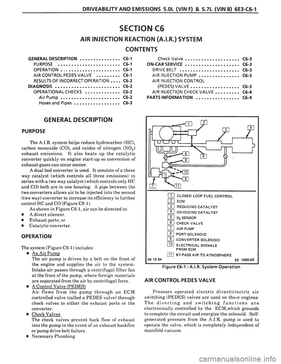
OPERATION
The system (Figure C6-1) includes:
@ An Air Pump
The air pump is driven by a belt on the front of
the engine and supplies the air to the system.
Intake air passes through a centrifugal filter fan
at the front of the pump; where foreign materials
are separated from the air by centrifugal force.
@ A Control Valve (PEDESl
Air flows from the pump through an ECM
controlled valve (called a PEDES valve) through
check valves to either the exhaust ports or the
converter.
@ Check Valves
The check valves prevent back flow of exhaust
into the pump in the event of
an exhaust backfire
or pump drive belt failure.
@ Necessary Plumbing
Check Valve .................... C6-3
ON-CAR SERVICE
.................... C6-3
DRIVEBELT ...................... C6-3
AIR INJECTION PUMP ............... C6-3
AIR INJECTION CONTROL
(PEDES) VALVE..
................ C6-3
AIRINJECTIONCHECKVALVE.. ....... C6-4
PARTS INFORMATION
................ C6-4
CLOSED LOOP FUEL CONTROL I
(2I ECM
1 REDUCING CATALYST
1 OXIDIZING CATALYST
1 0) SENSOR
1 CHECK VALVE
1 AIR PUMP
(BI PORT SOLENOID
( CONVERTER SOLENOID
llO) ELECTRICAL SIGNALS
FROM ECM
j BY-PASS AIR TO ATMOSPHERE
Figure C6-1 - A.I.R. System Operation
AIR CONTROL PEDES VALVE
Pressure operated electric divertleleclric air
switching (PEDES) valves are used on
these engines.
The diverting and switching functions are
electronically controlled by the
ECM,which grounds
to complete the circuit and energize the solenoid. Self-
generated pressure from the A.I.R. pump
is used to
operate the valve, which is completely independent of
manifold vacuum.
Page 958 of 1825
INDEX
SECTION PAGE
.................... Acceleration Mode C2-2
A/C On Signal
General Description
................. C1-4
......................... Diagnosis C1-5
Air Injection Check Valve
............... C6-4
Air Injection Control (Pedes) Valve
........ C6-1
Air Injection Reaction (A.I.R.) System
General Description
................. C6-1
......................... Diagnosis C6-2
Air Management Check (Pedes)
.......... C6-6
AirPump ........................... C6-2
........................... Service C6-3
...................... ALDL Connector A- 12
Automatic Transmission
Overdrive Switch Adjustment
.......... C8-3
Automatic Transmission Converter Clutch
(TCC) Electrical Diagnosis
.............. C8-6
Backfire
............................ B-5
Battery Voltage Correction Mode
......... C2-3
....................... Before Starting B-I
........................ Burnoff Relay C1-8
......................... Calpac Error 8-60
........................ Canister Hose C3-3
Canister Purge Solenoid
................ C3-3
Chart
A-1 :
.......... No Service Engine Soon Light A-1
0
Chart
A-2:
No ALDL Data. Or Won't Flash Code 12.
Or Service Engine Soon Light On Steady
. . A-1 2
Chart A-3:
Engine Cranks But Won't Run
.......... A-14
Chart A-7:
................ Fuel System Diagnosis A- 18
Chart A-9:
........... Cold Start Valve Circuit Test A-22
Chart
B-1:
Restricted Exhaust System Check ........ B-8
Chart
C-1A:
......... ParkINeutral Switch Diagnosis C1-10
Chart C-2A:
................. Injector Balance Test C2-18
Chart C-2C:
Idle Air Control (IAC) System Check ...... C2-20
SECTION PACE
Chart C-3:
........... Canister Purge Valve Check C3-4
Chart C-4:
................ Ignition System Check C4-4
Chart
6-5:
.......... Electronic Spark Control (ESC) C5-4
Chart C-6:
.............. Air Management Check C6-6
Chart C-7:
Exhaust Gas Recirculation
............. C7-4
Chart
C-8A:
Automatic Transmission Converter Clutch
............................. (TCC) C8-6
Chart C-8B:
Manual Transmission With Overdrive
.... C8-10
Chart C- 12
:
................. Cooling Fan Control C12-2
............................ Chuggle B-3
................... Clear Flood Mode.. C2-2
......................... Closed Loop C2-1
Code12
............................ C4-1
Code13
............................ A-24
Code14
............................ A-26
Code15
............................ A-28
Code21
............................ A-30
Code22
............................ A-32
Code23
............................ A-34
Code24
............................ A-36
Code25
............................ A-38
Code32
............................ A-40
Code33
............................ A-42
Code34
............................ A-44
Code36
............................ A-46
Code41
............................ A-48
Code42
............................ A-50 C4-2
Code43
............................ A-52
Code44
............................ A-54
Code45
............................ A-56
Code46
............................ A-58
Code54
............................ A-60
...................... Codes 51.52. 53 A-62
Cold Start Tube And Valve Assembly
...... C2-7
Cold Start Fuel
lnjection Sw~tch
.................. General Description C2-11
......................... Diagnosis A-22
.................. Component Location A-2
Coolant Temperature Sensor
.................. General Description C1-2
.......................... Diagnosis C1-4
A-26
........................... Service C1-7