1988 PONTIAC FIERO fuel pump
[x] Cancel search: fuel pumpPage 980 of 1825
DRIVEABILITY AND EMISSIONS - FUEL INJECTION 6E-19
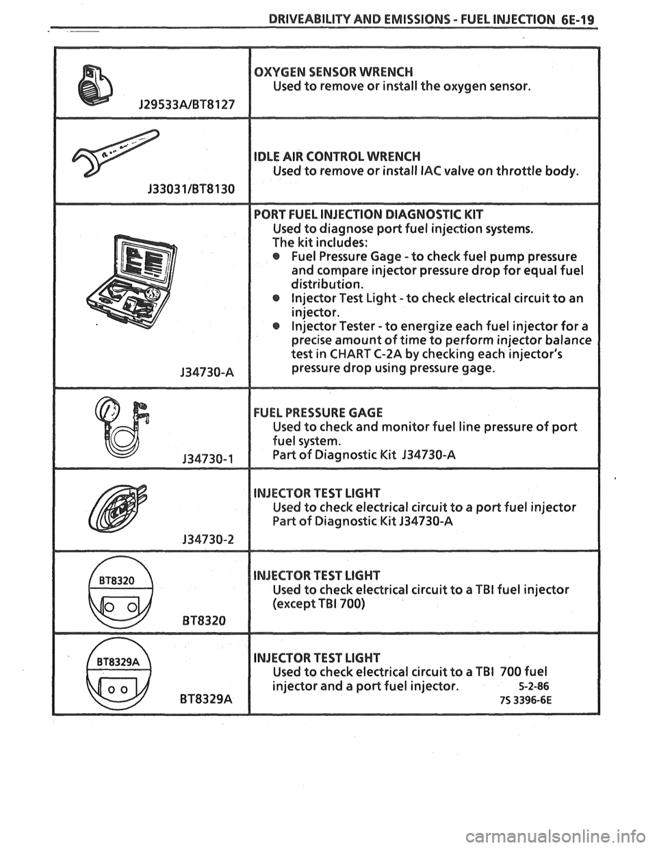
OXYGEN SENSOR WRENCH
Used to remove or install the oxygen sensor.
IDLE AIR CONTROL WRENCH
Used to remove or install IAC valve on throttle body.
PORT FUEL INJECTION DIAGNOSTIC KIT
Used to diagnose poPt fuel injection systems.
The kit includes:
@ Fuel Pressure Gage -to check fuel pump pressure
and compare injector pressure drop for equal fuel
distribution. lnjector Test Light -to check electrical circuit to an
injeclor.
@ Injector Tester - to energize each fuel injector for a
precise amount of time to perform injector balance
test in
CHART C-2A by checking each injector's
pressure drop using pressure gage.
FUEL PRESSURE GAGE
Used to check and monitor fuel line pressure of port
fuel system.
Part of Diagnostic Kit 134730-A
INJECTOR TEST LIGHT
Used to check electrical circuit to a port fuel injector
Pae of Diagnostic Kit 134730-A
INJECTOR TEST LIGHT
Used to check eledrical circuit to a TBI fuel injector
(except
TBI 700)
INJECTOR TEST LIGHT
Used to check electrical circuit to a TBI 700 fuel
injector and a port fuel injector.
5-2-86
75 3396-6E
Page 983 of 1825
6E-22 DRIVEABILITY AND EMISSIONS - FUEL INJECnIBN
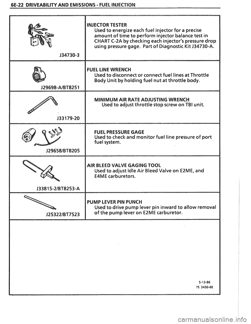
NJECTOR TESTER
Used to energize each fuel injector for a precise
amount of time to perform injector balance
test in
CHART
C-ZA by checking each injector's pressure drop
using pressure gage. Part of Diagnostic
Kit J34730-A.
FUEL LINE WRENCH
Used to disconnect or conned fuel lines at Throttle
MINIMUM AIR RATE ADJUSTING WRENCH
Used to adjust throttle stop screw on TBI unit.
FUEL PRESSURE GAGE
Used to check and monitor fuel line pressure of port
AIR BLEED VALVE GAGING TOOL
Used to adjust Idle Air Bleed Valve on EZME, and
E4ME carburetors.
PUMP LEVER PIN PUNCH
Used to drive pump lever pin inward to allow removal
J25322IBT7523 of the pump lever on E2ME carburetor.
Page 1210 of 1825
BOWER DISTRIBUTION
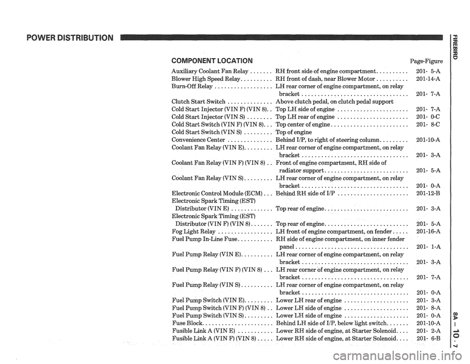
COMPONENT LOCATION Page-Figure
Auxiliary Coolant Fan Relay
. . . . . . . RH front side of engine compartment. . . . . . . . . .
Blower High Speed Relay. . . . . . . . . . RN front of dash, near Blower Motor . . . . . . . . . .
Burn-Off Relay . . . . . . . . . . . . . . . . . . LH rear corner of engine compartment, on relay
bracket
.................................
Clutch Start Switch . . . . . . . . . . . . . . Above clutch pedal, on clutch pedal support
Cold Start Injector (VIN F) (VIN
8). . Top LH side of engine . . . . . . . . . . . . . . . . . . . . . .
Cold Start Injector (VIN S) . . . . . . . . Top LH rear of engine . . . . . . . . . . . . . . . . . . . . . .
Cold Start Switch (VIN F) (VIN 8). . . Top center of engine. . . . . . . . . . . . . . . . . . . . . . . .
Cold Start Switch (VIN S) . . . . . . . . . Top of engine
Convenience Center
. . . . . . . . . . . . . . Behind IIP, to right of steering column. . . . . . . . .
Coolant Fan Relay (VIN E). . . . . . . . . LN rear corner of engine compartment, on relay
bracket
.................................
Coolant Fan Relay (VIN F) (VIN 8) . . Front of engine compartment, RH side of
radiator support.
. . . . . . . . . . . . . . . . . . . . . . . . .
Coolant Fan Relay (VIN S) . . . . . . . . . LH rear corner of engine compartment, on relay
bracket
.................................
Electronic Control Module (ECM) . . . Behind RN side of UP . . . . . . . . . . . . . . . . . . . . . .
Electronic Spark Timing (EST)
Distributor (VIN E)
. . . . . . . . . . . . . Top rear of engine. . . . . . . . . . . . . . . . . . . . . . . . . .
Electronic Spark Timing (EST)
Distributor (VIN F) (VIN
8). . . . . . . Top rear of engine. . . . . . . . . . . . . . . . . . . . . . . . . .
Fog Light Relay . . . . . . . . . . . . . . . . . LR front of engine compartment, on fender. . . . .
Fuel Pump In-Line Fuse. . . . . . . . . . . RR side of engine compartment, on inner fender
panel
...................................
Fuel Pump Relay (VIN E). . . . . . . . . . LN rear corner of engine compartment, on relay
bracket
.................................
Fuel Pump Relay (VIN F) (VIN 8) . . . LN rear corner of engine compartment, on relay
bracket
.................................
Fuel Pump Relay (VIN S) . . . . . . . . . . LH rear corner of engine compartment, on relay
bracket
.................................
Fuel Pump Switch (VIN E). . . . . . . . . Lower LN rear of engine . . . . . . . . . . . . . . . . . . . .
Fuel Pump Switch (VIN F) (VIN 8) . . Lower LN side of engine . . . . . . . . . . . . . . . . . . . .
Fuel Pump Switch (VIN S) . . . . . . . . . Lower LN side of engine . . . . . . . . . . . . . . . . . . . .
Fuse Block. . . . . . . . . . . . . . . . . . . . . . Behind LH side of IIP, below light switch. . . . . . .
Fusible Link A (VIN E) . . . . . . . . . . . Lower RN side of engine, at Starter Solenoid. . . .
Fusible Link A (VIN F) (VIN 8) . . . . . Lower RH side of engine, at Starter Solenoid. . . . 201- 6-B
Page 1250 of 1825
MULTI-PORT FUEL INJECTION: V6 VIN S
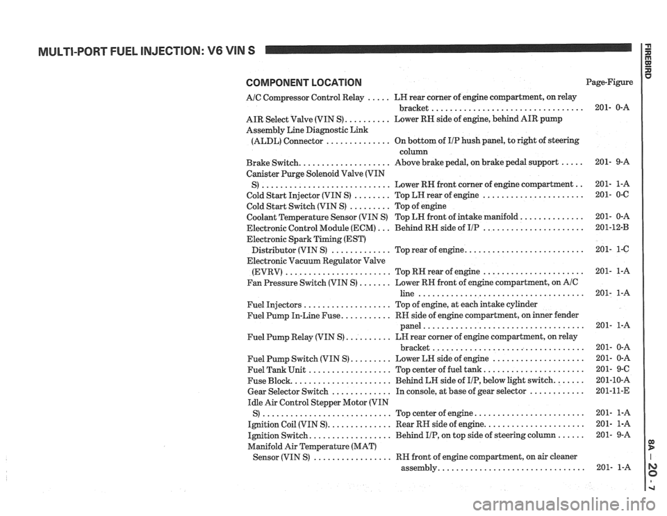
COMPONENT LOCATION
AIC Compressor Control Relay ..... LH rear corner of engine compartment, on relay
................................. bracket
AIR Select Valve (VIN S)
.......... Lower RN side of engine, behind AIR pump
Assembly Line Diagnostic Link
(ALDL) Connector
.............. On bottom of IIP hush panel, to right of steering
column
Brake Switch.
................... Above brake pedal, on brake pedal support .....
Canister Purge Solenoid Valve (VIN
............................ .. S) Lower RH front
corner of engine compartment
Cold Start Injector (VIN S)
........ Top LH rear of engine ......................
Cold Start Switch (VIN S) ......... Top of engine
Coolant Temperature Sensor (VIN S) Top LN front of intake manifold.
.............
Electronic Control Module (ECM) ... Behind RH side of IIP ......................
Electronic Spark Timing (EST)
......................... Distributor (VIN S) ............. Top rear of engine.
Electronic Vacuum Regulator Valve
(EVRV)
....................... TopRHrearofengine ......................
Fan Pressure Switch (VIN S) ....... Lower RH front of engine compartment, on AIC
line ....................................
Fuel Injectors ................... Top of engine, at each intake cylinder
Fuel Pump In-Line Fuse.
.......... RH side of engine compartment, on inner fender
panel
...................................
Fuel Pump Relay (VIN S) .......... LH rear corner of engine compartment, on relay
................................. bracket
Fuel Pump Switch (VIN S)
......... Lower LH side of engine ....................
Fuel Tank Unit .................. Top center of fuel tank ......................
Fuse Block. ..................... Behind LH side of IIP, below light switch. ......
Gear Selector Switch ............. In console, at base of gear selector ............
Idle Air Control Stepper Motor (VIN
S)
............................ Topcenterofengine ........................
Ignition Coil (VIN S). ............. Rear RH side of engine. .....................
Ignition Switch. ................. Behind IIP, on top side of steering column ......
Manifold Air Temperature (MAT)
................. Sensor (VIN S) RH front of engine compartment, on air cleaner
............................... assembly. Page-Figure
Page 1264 of 1825
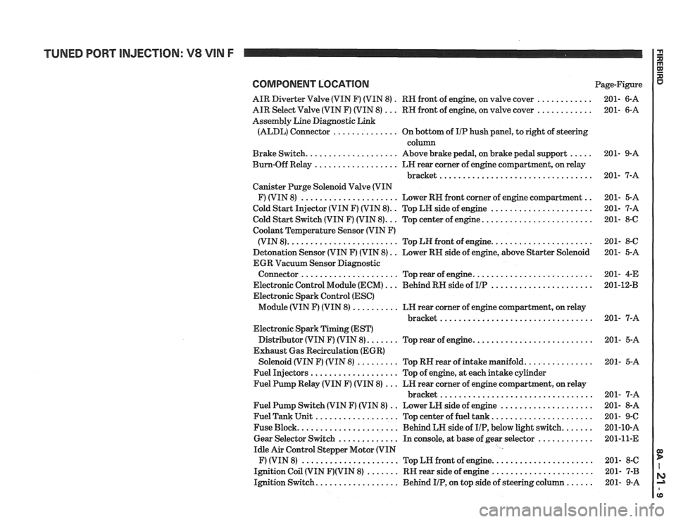
COMPONENT LOCATION Page-Figure
AIR Diverter Valve (VIN F) (VIN 8)
. RN front of engine, on valve cover ............ 201- 6-A
AIR Select Valve (VIN F) (VIN 8)
... RN front of engine, on valve cover ............ 201- 6-A
Assembly Line Diagnostic Link
(ALDL) Connector
.............. On bottom of IIP hush panel, to right of steering
column
Brake Switch.
................... Above brake pedal, on brake pedal support ..... 201- 9-A
Bum-Off Relay
.................. LN rear comer of engine compartment, on relay
bracket
................................. 201- 7-A
Canister Purge Solenoid Valve (VIN
F) (VIN 8)
..................... Lower RN front corner of engine compartment .. 201- 5-A
Cold Start Injector (VIN F) (VIN 8).
. Top LH side of engine ...................... 201- 7-A
.. ....................... Cold Start Switch (VIN F) (VIN 8). Top center of engine. 201- 8-6
Coolant
Temperature Sensor (VIN F)
..................... (VIN 8). ....................... Top LN front of engine. 201- 8-C
Detonation Sensor (VIN F) (VIN 8)
. . Lower RN side of engine, above Starter Solenoid 201- 5-A
EGR Vacuum Sensor Diagnostic
......................... Connector ..................... Top rear of engine. 201-
4-E
Electronic Control Module (ECM)
... Behind RN side of IIP ...................... 201-1243
Electronic Spark Control (ESC)
Module (VIN F) (VIN 8)
.......... LN rear corner of engine compartment, on relay
............................... bracket.. 201- 7-A
Electronic Spark Timing (EST)
Distributor (VIN
F) (VIN 8). ...... Top rear of engine. ......................... 201- 5-A
Exhaust Gas Recirculation (EGR)
Solenoid (VIN
F) (VIN 8) ......... Top RN rear of intake manifold. .............. 201- 5-A
Fuel Injectors
................... Top of engine, at each intake cylinder
Fuel Pump Relay (VIN
F) (VIN 8) ... LN rear corner of engine compartment, on relay
bracket
................................. 201- 7-A
Fuel Pump Switch (VIN
F) (VIN 8) .. Lower LN side of engine .................... 201- 8-A
Fuel Tank Unit
.................. Top center of fuel tank ...................... 201- 9-C
Fuse Block.
..................... Behind LH side of IIP, below light switch. ...... 201-10-A
Gear Selector Switch
............. In console, at base of gear selector ............ 201-11-E
Idle Air Control Stepper Motor (VIN
F) (VIN 8)
..................... Top LN front of engine. ..................... 201- 8-C
Ignition Coil (VIN
F)(VIN 8) ....... RN rear side of engine ...................... 201- 7-B
Ignition Switch.
................. Behind IIP, on top side of steering column ...... 201- 9-A
Page 1277 of 1825
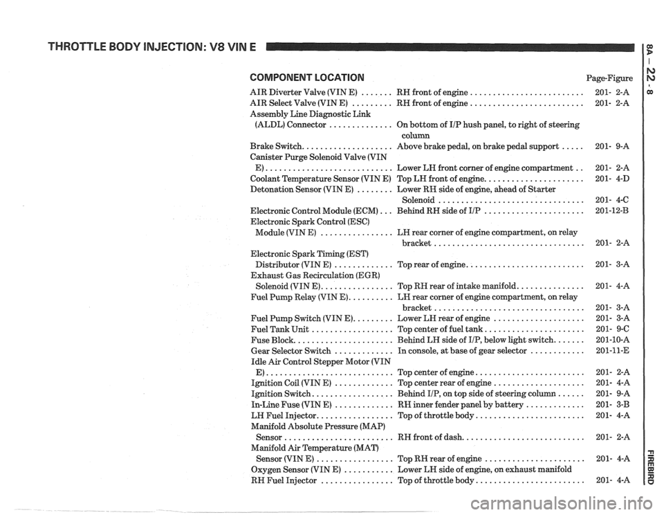
THROTTLE BODY INJECTION: V8 VIN E
COMPONENT LOCATION Page-Figure
AIR Diverter Valve (VIN E)
....... RH front of engine .........................
AIR Select Valve (VIN E) ......... RH front of engine .........................
Assembly Line Diagnostic Link
(ALDL) Connector
.............. On bottom of IIP hush panel, to right of steering
column
Brake Switch.
................... Above brake pedal, on brake pedal support .....
Canister Purge Solenoid Valve (VIN
E)
............................ Lower LH front corner of engine compartment ..
Coolant Temperature Sensor (VIN E) Top LH front of engine. .....................
Detonation Sensor (VIN E) ........ Lower RK side of engine, ahead of Starter
Solenoid
................................
Electronic Control Module (ECM) ... Behind RH side of IIP ......................
Electronic Spark Control (ESC)
Module (VIN E)
................ LH rear corner of engine compartment, on relay
................................. bracket
Electronic Spark Timing (EST)
Distributor (VIN E)
............. Top rear of engine. .........................
Exhaust Gas Recirculation (EGR)
Solenoid (VIN E).
............... Top RH rear of intake manifold. ..............
Fuel Pump Relay (VIN E). ......... LH rear corner of engine compartment, on relay
................................. bracket
Fuel Pump Switch (VIN E).
........ Lower LH rear of engine ....................
Fuel Tank Unit .................. Top center of fuel tank. .....................
Fuse Block. ..................... Behind LH side of IIP, below light switch. ......
Gear Selector Switch ............. In console, at base of gear selector ............
Idle Air Control Stepper Motor (VIN
E)
............................ Topcenterofengine ........................
Ignition Coil (VIN E) ............. Top center rear of engine ....................
Ignition Switch. ................. Behind IIP, on top side of steering column ......
In-Line Fuse (VIN E) ............. RW inner fender panel by battery .............
LW Fuel Injector. ................ Top of throttle body. .......................
Manifold Absolute Pressure (MAP)
Sensor
........................ RH front of dash. ..........................
Manifold Air Temperature (MAT)
Sensor (VIN
E) ................. Top RK rear of engine ......................
Oxygen Sensor (VIN E) ........... Lower LH side of engine, on exhaust manifold
RH Fuel Injector
................ Top of throttle body. .......................
Page 1289 of 1825
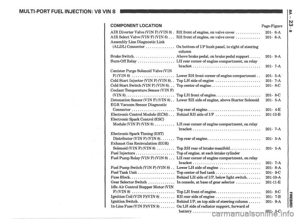
MULTI-PORT FUEL INJECTION: V8 VIN 8 It
COMPONENT LOCATION Page-Figure
. ............ AIR Diverter Valve (VIN F) (VIN 8)
RN front of engine. on valve cover 201- 6-A
............ AIR Select Valve (VIN F) (VIN 8) ... RW front of engine. on valve cover 201- 6-A
Assembly Line Diagnostic Link
(ALDL) Connector
.............. On bottom of I/P hush panel. to right of steering
column
..... Brake Switch .................... Above brake pedal. on brake pedal support 201- 9-A
Burn-Off Relay
.................. LH rear corner of engine compartment. on relay
bracket
................................. 201- 7-A
Canister Purge Solenoid Valve (VIN
.. F) (VIN 8) ..................... Lower RH front corner of engine compartment 201- 5-A'
.. ...................... Cold Start Injector (VIN F) (VIN 8) Top LH side of engine 201- 7-A
........................ Cold Start Switch (VIN F) (VIN 8) ... Top center of engine 201- 8-6
Coolant Temperature Sensor (VIN F)
...................... (VIN 8) ........................ Top LN front of engine 201- 8-C
Detonation Sensor (VIN F) (VIN 8)
. . Lower RN side of engine. above Starter Solenoid 201- 5-A
EGR Vacuum Sensor Diagnostic
.......................... Connector ..................... Top rear of engine 201- 4-E
...................... Electronic Control Module (ECM) ... Behind RH side of IIP 201-12-B
Electronic Spark Control (ESC)
Module (VIN F) (VIN 8)
.......... LH rear corner of engine compartment. on relay
bracket
................................. 201- 7-A
Electronic Spark Timing (EST)
.......................... Distributor (VIN F) (VIN 8) ....... Top rear of engine 201- 5-A
Exhaust Gas Recirculation (EGR)
............... Solenoid (VIN F) (VIN 8) ......... Top RN rear of intake manifold 201- 5-A
Fuel Injectors
................... Top of engine. at each intake cylinder
Fuel Pump Relay (VIN F) (VIN 8)
... LH rear corner of engine compartment. on relay
bracket
................................. 201- 7-A
.. ................... Fuel Pump Switch (VIN F) (VIN 8)
Lower LH side of engine : 201- 8-A
...................... Fuel Tank Unit .................. Top center of fuel tank 201- 9-C
....... Fuse Block ...................... Behind LH side of IIP. below light switch 201-10-A
............ Gear Selector Switch ............. In console. at base of gear selector 201-11-E
Idle Air Control Stepper Motor (VIN
...................... F) (VIN 8) ..................... Top LN front of engine 201- 8-C
...................... Ignition Coil (VIN F)(VIN 8) ....... RH rear side of engine 201- 7-B
...... Ignition Switch .................. Behind IIP. on top side of steering column 201- 9-A
In-Line Fuse (VIN F)(VIN 8) ....... On LH side of radiator support. forward of
battery
................................. 201- 5-C
Page 1303 of 1825
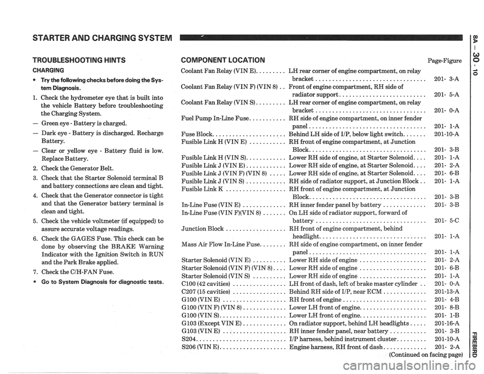
STARTER AND CHARGING SYSTEM
TROUBLESHOOTING HINTS
CHARGING
* Try the following checks before doing the Sys-
tem Diagnosis
.
1 . Check the hydrometer eye that is built into
the vehicle Battery before troubleshooting
the Charging System
.
- Green eye . Battery is charged .
. Dark eye . Battery is discharged . Recharge
Battery
.
- Clear or yellow eye . Battery fluid is low .
Replace Battery .
2 . Check the Generator Belt .
3 . Check that the Starter Solenoid terminal B
and battery connections are clean and tight
.
4 . Check that the Generator connector is tight
and that the Generator battery terminal is
clean and tight
.
5 . Check the vehicle voltmeter (if equipped) to
assure accurate voltage readings
.
6 . Check the GAGES Fuse . This check can be
done by observing the BRAKE Warning
Indicator with the Ignition Switch in RUN
and the Park Brake applied
.
7 . Check the GIN-FAN Fuse .
Go to System Diagnosis for diagnostic tests .
COMPONENT LOCATION Page-Figure
Coolant Fan Relay (VIN
E) ......... LH rear corner of engine compartment. on relay
bracket
................................. 201- 3-A
Coolant Fan Relay (VIN F) (VIN 8)
. . Front of engine compartment. RH side of
radiator support
.......................... 201- 5-A
Coolant Fan Relay (VIN S)
......... LN rear corner of engine compartment. on relay
bracket
................................. 201- 0-A
Fuel Pump In-Line Fuse
........... RH side of engine compartment. on inner fender
panel
................................... 201- 1-A
Fuse Block
...................... Behind LN side of IIP. below light switch ....... 201-10-A
Fusible Link H (VIN E)
........... RH front of engine compartment. at Junction
................................... Block 201- 3-B
Fusible Link
H (VIN S) ............ Lower RN side of engine. at Starter Solenoid .... 201- 1-A
Fusible Link
J (VIN E) ............ Lower RH side of engine. at Starter Solenoid .... 201- 2-A
Fusible Link
J (VIN F) (VIN 8) ..... Lower RH side of engine. at Starter Solenoid .... 201- 6-B
Fusible Link
J (VIN S) ............ RH side of radiator support. at Junction Block .. 201- 1-A
Fusible Link
K .................. RH front of engine compartment. at Junction
................................... Block 201- 3-B
In-Line Fuse (VIN E)
............. RH inner fender panel by battery ............. 201- 3-B
In-Line Fuse (VIN
F)(VIN 8) ....... On LH side of radiator support. forward of
................................. battery 201- 5-6
.................. Junction Block RH
front of engine compartment. behind
................................ headlight 201- 1-A
........ Mass Air Flow In-Line Fuse RR side of engine compartment. on inner fender
................................... panel 201- 1-A
Starter Solenoid (VIN E)
.......... Lower RH side of engine .................... 201- 2-A
Starter Solenoid (VIN F) (VIN
8) .... Lower RH side of engine .................... 201- 6-B
Starter Solenoid (VIN S)
.......... Lower RN side of engine .................... 201- 1-A
el00 (42 cavities) ................ LH front of dash. left of brake master cylinder .. 201- 0-A
C207 (15 cavities)
................ Behind RH side of IIP. near ECM ............. 201-13-A
G100 (VIN E) ................... RH front of engine ......................... 201- 4-B
G100 (VIN F) (VIN 8) ............. Lower LH front of engine .................... 201- 8-B
G100 (VIN S) .................... Lower LH front of engine .................... 201- 1-B
6103 (Except VIN E) ............. On radiator support. behind LH headlights ..... 201-16-A
6.103 (VIN E) ................... RH inner fender panel. near battery ........... 201- 3-B
S204
........................... IIP harness. behind instrument cluster ......... 201-10-A
S206 (VIN
E) .................... Engine harness. RH front of dash ............. 201- 2-A
(Continued on facing page)