1988 PONTIAC FIERO fuel pump
[x] Cancel search: fuel pumpPage 742 of 1825
DRIVEABILITY AND EMISSIONS 2.8L (VIN S) 6E3-CZ-7
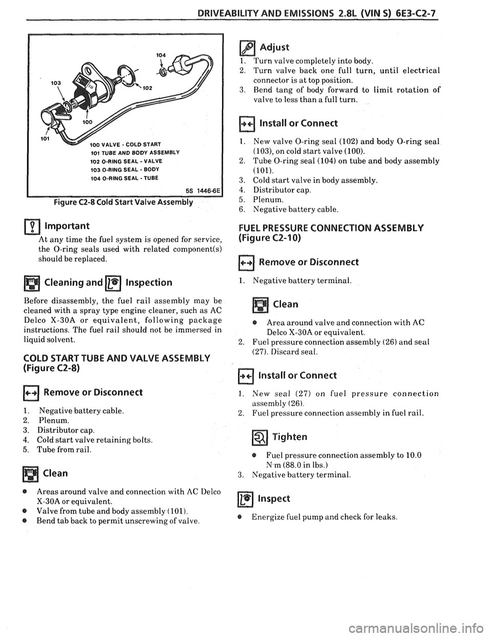
100 VALVE - COLD START
101 TUBE AND BODY ASSEMBLY
102 O-RING SEAL -VALVE
103 O-RING SEAL - BODY
104 O-RING SEAL -TUBE
Figure C2-8 Cold Start Valve Assembly
important
At any time the fuel system is opened for service,
the O-ring seals used with related
component(s)
should be replaced.
a Cleaning and a Inspection
Before disassembly, the fuel rail assembly may be
cleaned with a spray type engine cleaner, such as AC
Delco X-30A or equivalent, following package
instructions. The fuel rail should not be immersed in
liquid solvent.
COLD START TUBE AND VALVE ASSEMBLY
(Figure C2-8)
Remove or Disconnect
1. Negative battery cable.
2. Plenum.
3. Distributor cap.
4. Cold start valve retaining bolts.
5. Tube from rail.
Clean
@ Areas around valve and connection with AC Delco
X-30A or equivalent.
@ Valve from tube and body assembly (101).
@ Bend tab back to permit unscrewing of valve.
@ Adjust
1. Turn valve completely into body.
2. Turn valve back one full turn, until electrical
connector is at top position.
3. Bend tang of body forward to limit rotation of
valve to less than
a full turn.
Install or Connect
1. New valve O-ring seal (102) and body O-ring seal
(103), on cold start valve (100).
2. Tube O-ring seal (104) on tube and body assembly
(101).
3. Cold start valve in body assembly.
4. Distributor cap.
5. Plenum.
6. Negative battery cable.
FUEL PRESSURE CONNECTION ASSEMBLY
(Figure
C2-I 0)
Remove or Disconnect
1. Negative battery terminal.
Clean
@ Area around valve and connection with AC
Delco X-30A or equivalent.
2. Fuel pressure connection assembly (26) and seal
(27). Discard seal.
Install or Connect
1. New seal (27) on fuel pressure connection
assembly
(26).
2. Fuel pressure connection assembly in fuel rail.
Tighten
@ Fuel pressure connection assembly to 10.0
N.m (88.0 in lbs.)
3. Negative battery terminal.
a inspect
@ Energize fuel pump and check for leaks.
Page 744 of 1825
DRIVEABILITY AND EMISSIONS 2.8L (VIN S) 6E3-C2-9
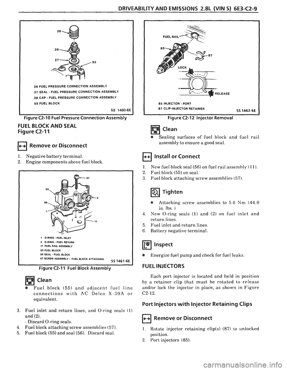
26 FUEL PRESSURE CONNECTION ASSEMBLY
27 SEAL - FUEL PRESSURE CONNECTION ASSEMBLY
28 CAP - FUEL PRESSURE CONNECTION ASSEMBLY
55 FUEL BLOCK
Figure C2-10 Fuel Pressure Connection Assembly
FUEL BLOCK AND SEAL
Figure CZ-I 1
Remove or Disconnect
1. Negative battery terminal.
2. Engine components above fuel block.
I O-RING -FUEL INLET 2 O-RING . FUEL RETURN 11 FUEL RAlL ASSEMBLY 55 FUEL BLOCK 56 SEAL -FUEL BLOCK 57 SCREW ASSEMBLY - FUEL BLOCK ATTACHING 55 1461-6E
Figure C2-11 Fuel Block Assembly
Clean
@ Fuel block (55) and adiacent fuel line
connections with
AC ~elco X-30A or
equivalent.
3. Fuel inlet and return lines, and O-ring seals (1)
and (2).
- Discard O-ring seals.
4. Fuel block attaching screw assemblies
(57).
5. Fuel block (55) and seal (56). Discard seal.
FUEL RAlL
REL
85 INJECTOR -PORT
87 CLIP-INJECTOR RETAINER
Figure C2-12 Injector Removal
- @ Sealing surfaces of fuel block and fuel rail
assembly to ensure a good seal.
Install or Connect
1. New fuel block sea1 (56) on fuel rail assembly ( 1 I).
2. Fuel block (55) on seal.
3. Fuel block attaching screw assemblies (57).
Tighten
@ Attaching screw assemblies to 5.0 Nm (44.0
in. Ibs.
)
4. New O-ring seals (1) and (2) on fuel inlet and
return lines.
5. Fuel inlet and return lines.
6. Battery negative terminal.
Inspect
@ Energize fuel pump and check for fuel leaks
FUEL INJECTORS
Each port injector is located and held in position
by a retainer clip that must be rotated to release
and/or lock the injector in place, as shown in Figure
C2-12.
Port Injectors with lnjector Retaining Clips
Remove or Disconnect
1. Rotate injector retaining clip(s) (87) to unlocked
position.
2. Port in*jectors (85).
Page 752 of 1825
DRIVEABILITY AND EMISSIONS 2.8L (VIN 5) 6E3-C2-17
FUEL PUMP RELAY
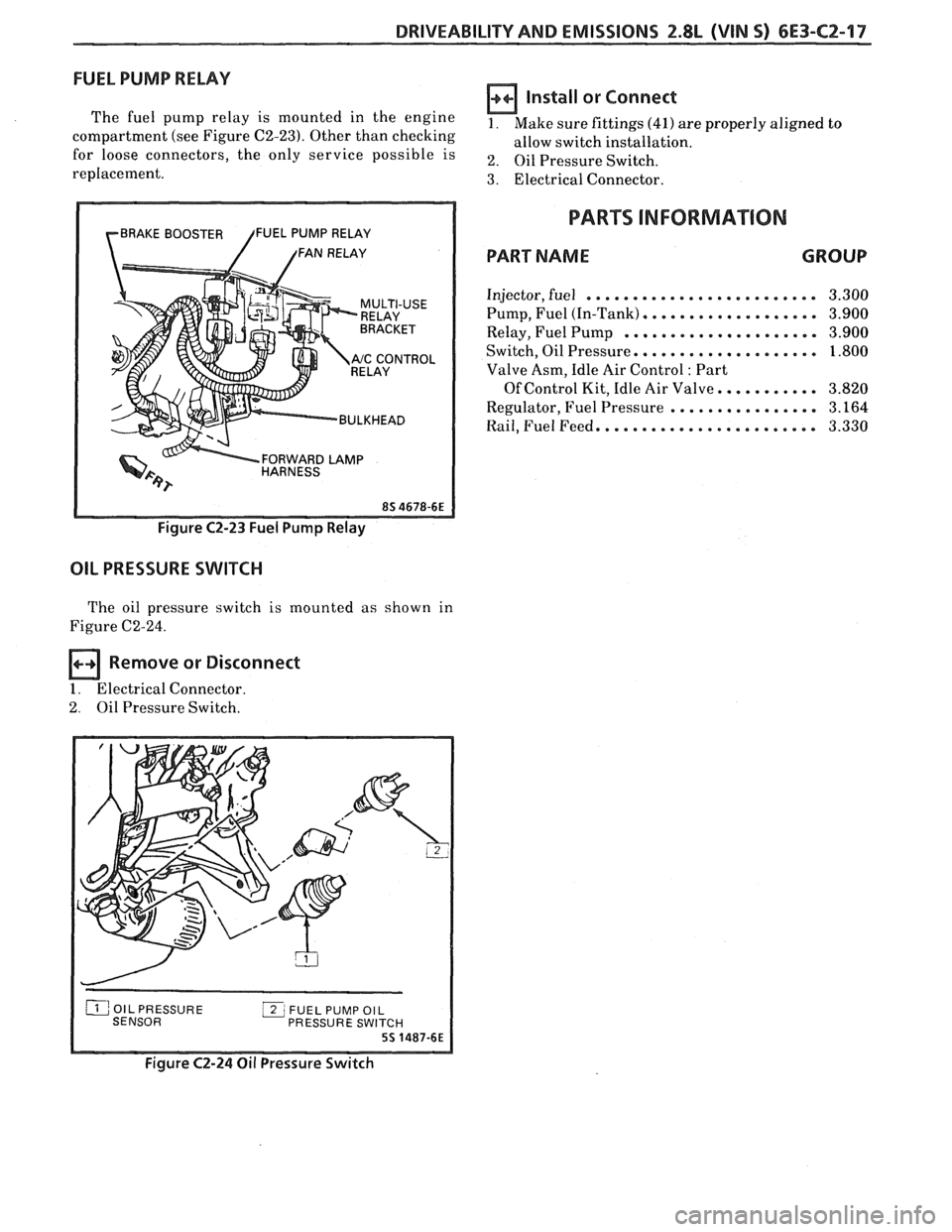
The fuel pump relay is mounted in the engine
compartment (see Figure C2-23). Other than checking
for loose connectors, the only service possible is
replacement.
rBRAKE BOOSTER /FUEL PUMP RELAY
/ /FAN RELAY
RELAY
Y '"ccONT"L
BULKHEAD
FORWARD
LAMP HARNESS
Figure C2-23 Fuel Pump Relay
OIL PRESSURE SWITCH
The oil pressure switch is mounted as shown in
Figure C2-24.
Remove or Disconnect
1. Electrical Connector.
2. Oil Pressure Switch.
Install or Connect
1. Make sure fittings (41) are properly aligned to
allow switch installation.
2. Oil Pressure Switch.
3. Electrical Connector.
PARTS INFORMATION
PART NAME GROUP
Injector, fuel ......................... 3.300
Pump, Fuel (In-Tank)
................... 3.900
Relay, Fuel Pump
..................... 3.900
Switch, Oil Pressure.
................... 1.800
Valve Asm, Idle Air Control
: Part
Of Control Kit, Idle Air Valve.
.......... 3.820
Regulator, Fuel Pressure
................ 3.164
Rail, Fuel Feed. ....................... 3.330
PRESSURE SWI
Figure C2-24 Oil Pressure Switch
Page 753 of 1825
6E3-C2-18 2.8L (VIN S) DRIVEABILITY AND EMISSIONS
CHART C-2A
INJECTOR BALANCE TEST
The injector balance tester is a tool used to turn the injector on for a precise
amount of time, thus spraying a measured amount of fuel into the manifold.
This causes a drop in fuel rail pressure that we can record and compare between
each injector. All injectors should have the same amount of pressure drop
( k 10
kpa). Any injector with a pressure drop that is 10 kpa (or more) greater or less
than the average drop of the other injectors should be considered faulty and
replaced.
Engine "cool down" period
(10 minutes) is necessary to avoid irregular
readings due to "Hot Soak" fuel boiling. With ignition
"OFF" connect fuel gauge
5347301 or equivalent to fuel pressure tap. Wrap a shop towel around fitting
while connecting gage to avoid fuel spillage.
Disconnect harness connectors at all injectors, and connect injector tester
J-
34730-3, or equivalent, to one injector. On Turbo equipped engines, use adaptor
harness furnished with injector tester to energize injectors that are not
accessible. Follow manufacturers instructions for use of adaptor harness.
Ignition must be
"OFF" at least 10 seconds to complete ECM shutdown cycle.
Fuel pump should run about
2 seconds after ignition is turned "ON". At this
point, insert clear tubing attached to vent valve into a suitable container and
bleed air from gauge and hose to insure accurate gauge operation. Repeat this
step until all air is bled from gauge.
STEP 2
Turn ignition "OFF" for 10 seconds and then "ON" again to get fuel pressure
to its maximum. Record this initial pressure reading. Energize tester one time
and note pressure drop at its lowest point (Disregard any slight pressure
increase after drop hits low point.). By subtracting this second pressure reading
from the initial pressure, we have the actual amount of injector pressure drop.
STEP 3
Repeat step 2 on each injector and compare the amount of drop. Usually, good
injectors will have virtually the same drop. Retest any injector that has
a
pressure difference of lOkPa, either more or less than the average of the other
injectors on the engine. Replace any injector that also fails the retest. If the
pressure drop of all injectors is within
lOkPa of this average, the injectors
appear to be flowing properly. Reconnect
them and review "Symptoms," Section
"B".
NOTE: The entire test should not be repeated more than once without
running the engine to prevent flooding. (This includes any retest on
fa ulty injectors).
Page 759 of 1825
6E3-C3-2 2.8L (VIN S) DRIVEABILITY AND EMISSIONS
The "CONTROL VAC" tube on the purge valve of the
canister is connected to a ported vacuum source.
When the engine is above idle speed, sufficient
vacuum is available to open the purge valve
diaphragm. Vapors are purge through the solenoid to
the combustion chamber.
This system also has a Tank Pressure Control
Valve to control the flow of vapors to the canister.
TANK PRESSURE CONTROL VALVE
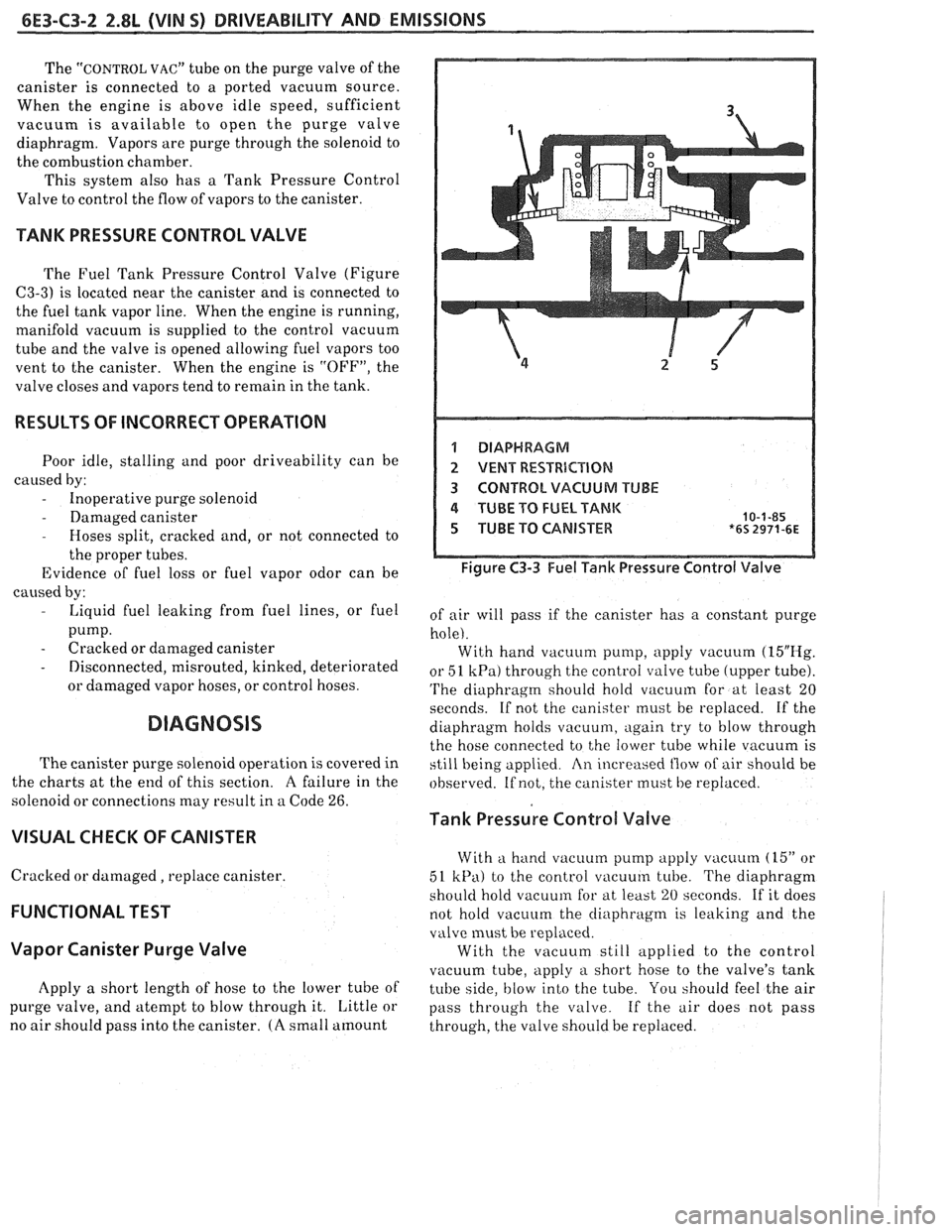
The Fuel Tank Pressure Control Valve (Figure
C3-3) is located near the canister and is connected to
the fuel tank vapor line. When the engine is running,
manifold vacuum is supplied to the control vacuum
tube and the valve is opened allowing
fuel vapors too
vent to the canister. When the engine is "OFF", the
valve closes and vapors tend to remain in the tank.
RESULTS OF INCORRECT OPERATION
Poor idle, stalling and poor driveability can be
caused by:
- Inoperative purge solenoid
- Damaged canister - Hoses split, cracked and, or not connected to
the proper tubes.
Evidence of fuel loss or fuel vapor odor can be
caused by:
- Liquid fuel leaking from fuel lines, or fuel
pump.
- Cracked or damaged canister
- Disconnected, misrouted, kinked, deteriorated
or damaged vapor hoses, or control hoses.
DIAGNOSIS
The canister purge solenoid operation is covered in
the charts
at the end of this section. A failure in the
solenoid or connections may result in a Code
26.
VISUAL CHECK OF CANISTER
Cracked or damaged, replace canister.
FUNCTIONAL TEST
Vapor Canister Purge Valve
Apply a short length of hose to the lower tube of
purge valve, and atempt to blow through it. Little or
no air should pass into the canister.
(A small amount
1 DIAPHRAGM
2 VENT RESTRBCBIQN
3 CONTROL VACUUM TUBE
4 TUBE TO FUEL TANK 10-1-85 5 TUBE TO CANISTER *6s 2971-6~
Figure C3-3 Fuel Tank Pressure Control Valve
of air will pass if the canister has a constant purge
hole). With hand vacuum pump, apply vacuum
(15"E-Ig.
or 51 kPa) through the control valve tube (upper tube).
'I'he diaphragm should hold vacuum for at least 20
seconds. If not the canister must be replaced. If the
diaphragm holds
vacuu111, again try to blow through
the hose connected to the lower tube while vacuum is
still being applied
An increased flow of air should be
observed. If not, the canister must be replaced.
Tank Pressure Control Valve
With a hand vacuum pump apply vacuum (15" or
51
kPa) to the control vacuum tube. The diaphragm
shoi~ld hold vacuum for at least 20 seconds. If it does
not hold vacuum the
cliaphragnl is leaking and the
valve must be replaced.
With the vacuum still applied to the control
vacuum tube, apply
a short hose to the valve's tank
tube side,
blow into the tube. You should feel the air
pass through the valve. If the
air does not pass
through, the valve should be replaced.
Page 771 of 1825
6E3-C6-2 2.8L (WIN 5) DRIVEABILITY AND EMISSIONS
When the solenoid is de-energized, the pressurized
air from the air pump is allowed to enter the decel
timing chamber. This places sufficient pressure on
the metering valve diaphragm to overcome spring
tension, closing the
valve,causing air to divert to the
silencer.
At higher engine speeds, excess air is exhausted to
the silencer through the pressure relief valve. (Figure
C6-1)
Deceleration Valve
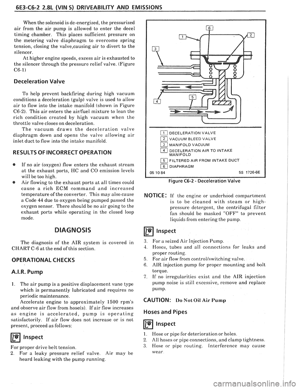
To help prevent backfiring during high vacuum
conditions a deceleration (gulp) valve is used to allow
air to flow into the intake manifold (shown in Figure
C6-2). This air enters the airlfuel mixture to lean the
rich condition created by high vacuum when the
throttle valve closes on deceleration.
The vacuum draws the deceleration valve
diaphragm down and opens the valve allowing air
inlet duct to flow into the intake manifold.
RESULTS OF INCORRECT OPERATION
@ If no air (oxygen) flow enters the exhaust stream
at the exhaust ports, HC and
CO emission levels
will be too high.
@ Air flowing to the exhaust ports at all times could
cause
a rich ECM command and increased
temperature of the converter. This may also cause
a Code
44 due to oxygen being pumped passed the
oxygen sensor. There should be no air going to the
exhaust ports while operating in the closed loop
mode.
DIAGNOSIS
The diagnosis of the AIR system is covered in
CHART C-6 at the end of this section.
OPERATIONAL CHECKS
A.I.R. Pump
1. The air pump is a positive displacement vane type
which is permanently lubricated and requires no
periodic maintenance.
Accelerate engine to approximately
1500 rpm's
and observe air flow from
hose(s). If air flow increases
as engine is accelerated, pump is operating
satisfactorily. If air flow does not increase or is not
present, proceed as follows:
Inspect
For proper drive belt tension.
2. For a leaky pressure relief valve. Air may he
heard leaking with the pump running.
DECELERATION VALVE
1 VACUUM BLEED VALVE
1 MANIFOLD VACUUM
1 DECELERATION AIR TO INTAKE
MANIFOLD
1 FILTERED AIR FROM INTAKE DUCT
/ DIAPHRAGM
05 10 84 5s 1726-6E
Figure C6-2 - Deceleration Valve
NOTICE: If the engine or underhood compartment
is to he cleaned with
steam or high-
pressure detergent, the centrifugal filter
fan should be masked "OFF7' to prevent
liquids from entering the pump.
Inspect
3. For a seized Air Injection Pump.
3. Hoses, tubes and all connections for leaks and
proper routing.
5, For air flow from controllswitching valve.
6. AIR injection pump for proper mounting and bolt
torque.
7. If no irregularities exist and the AIR injection
pump noise is still excessive, remove and replace
pump.
CAUTION: Do Not Oil Air Pump
Hoses and Pipes
Inspect
1. Hose or pipe for deterioration or holes.
2. All hoses or pipe connections, and clamp tightness.
3. Hose or pipe routing. Interference may cause
wear
Page 804 of 1825
DRIVEABILITY AND EMISSIONS 5.OL (VIM F) & 5.7L(VIN 8) 6E3-A-1
DIAGNOSIC CIRCUIT CHECK Cold Oxygen Sensor
The "Diagnostic Circuit Check" verifies the On some engines. the Oxygen Sensor will cool off
system is functioning correctly
. Some special after only a short period of operation at idle . This will
considerations to keep in mind while making the put the system into "Open Loop"
. To restore "Closed
"Diagnostic Circuit Check" are:
I. oop" operation. run the engine at part throttle
several minutes and accelerate from idle to part
Blocking Drive Wheels throttle a few times .
The vehicle drive wheels must be blocked while Basic Procedure
checking the system .
If you have not reviewed the Basic Information on
how to use the Diagnostic Procedures. go to the
Introduction of this section
.
SECTION A
ENGINE COMPONENTS
/WIRING DIAGRAMS 1 DIAGNOSTIC CHARTS
........................................................ Component Locations Page A-2
...................................................... Wiring Diagrams. (1 of 4) Page
A-3
ECMTerminal EndView ...................................................... PageA-7
.................................................. Scan Diagnostic Circuit Check Page
A-8
........................................ . No "Service Engine Soon" Light Chart A-I Page A-10
No ALDL Data
. "Service Engine Soon" Light On Steady (Won't Flash Code 12) . Chart A-2 ..... Page A-12
................................... . Engine Cranks But Won't Run Chart A.3, (1 of 2) Page A-14
......................................... Fuel System Diagnosis . Chart A.7, (1 of 2) Page
A-18
.................................................... . Cold Start Valve Chart A-9 Page A-22
..................................................... Code 13 O2 Sensor Circuit Page
A-24
.................................. Code 14 Coolant Temperature Sensor Circuit (High) Page
A-26
.................................. Code 15 Coolant Temperature Sensor Circuit (Low) Page
A-28
................................. Code 2 I Throttle Position Sensor (TPS) Circuit (High) Page
A-30
.................................. Code 22 Throttle Position Sensor (TPS) Circuit (Low) Page
A-32
......................... Code 23 Manifold Air Temperature (MAT) Sensor Circuit (Low) Page
A-34
........................................ Code 24 Vehicle Speed Sensor (VSS) Circuit Page
A-36
......................... Code 25 Manifold Air Temperature (MAT) Sensor Circuit (High) Page
A-38
..................................... Code 32 Exhaust Gas Recirculation (EGR) Circuit Page
A-40
................................... Code 33 Mass Air Flow (MAF) Sensor Circuit (High) Page
A-42
................................... Code 34 Mass Air Flow (MAF) Sensor Circuit (Low) Page
A-44
................................. Code 36 Mass Air Flow (MAF) Sensor Burn-Off Circuit Page
A-46
................................................... Code 41 Cylinder Select Error Page
A-48
...................................... Code 42 Electronic Spark Timing (EST) Circuit Page
A-50
...................................... Code 43 Electronic Spark Control (ESC) Circuit Page
A-52
............................................ Code 44 Oxygen Sensor Circuit (Lean) Page
A-54
............................................. Code 45 Oxygen Sensor Circu~t (Rich) Page
A-56
......................................... Code 46 Vehicle Anti Theft System (VATS) Page
A-58
Code51
MEM.CAL ........................................................... PageA-62
........................................................ Code52CALPAKError PageA-62
................................................... Code 53 System Over Voltage Page
A-62
................................................ Code 54 Fuel Pump Circu~t (Low) Page
2-60
Page 805 of 1825
6E3-A-2 5.OL (VIN F) & 5.7L(VIN 8) DRIVEABILITY AND EMISSIONS
COMPUTER HARNESS [7 CONTROLLED DEVICES 0 INFORMATION SENSORS
C1 Electronic Control Module (ECM) 1 Fuel injector €3 Exhaust oxygen
C2 ALDL diagnostic connector 2 Idle air control motor C Throttle position
C3 "SERVICE ENGINE SOON" light
3 Fuel pump relay D Coolant temperature
C4
ECMpower 5 Trans. Converter Clutch connector F Vehicle speed
C5 ECM harness ground
7 Electronic Spark Control module J ESCknock C6 Fuse panel
C8 Fuel pump test connector (ALDL "G") Primary fan relay K Mass Air Flow
C9 Fuel pump1ECM fuse 9 Air injection converterldivert solenoid T Manifold Air Temperature
10 Air injection port solenoid
U AIC pressure fan switch . ., .. .. NOT ECM CONNECTED 12 EGR vacuum solenoid w EGR temp. diagnostic switch
N1 Crankcase vent valve (PCV) 15 Fuel vapor canister solenoid
N5 Engine temp. sensor (gage overheat)
16 MAF sensor power relay
N7 Oil pressure sensor (gage) 17 MAF sensor burn-off relay
N8 Oil pressure switch (fuel pump) 18 Primary cooling fan
N10 Cold start valve
N11 Cold start fuel injection switch
N12 Secondary cooling fan
N13 Cooling fan temperature switch
N14 Secondary cooling fan relay 7-13-87
*8S 4274-6E
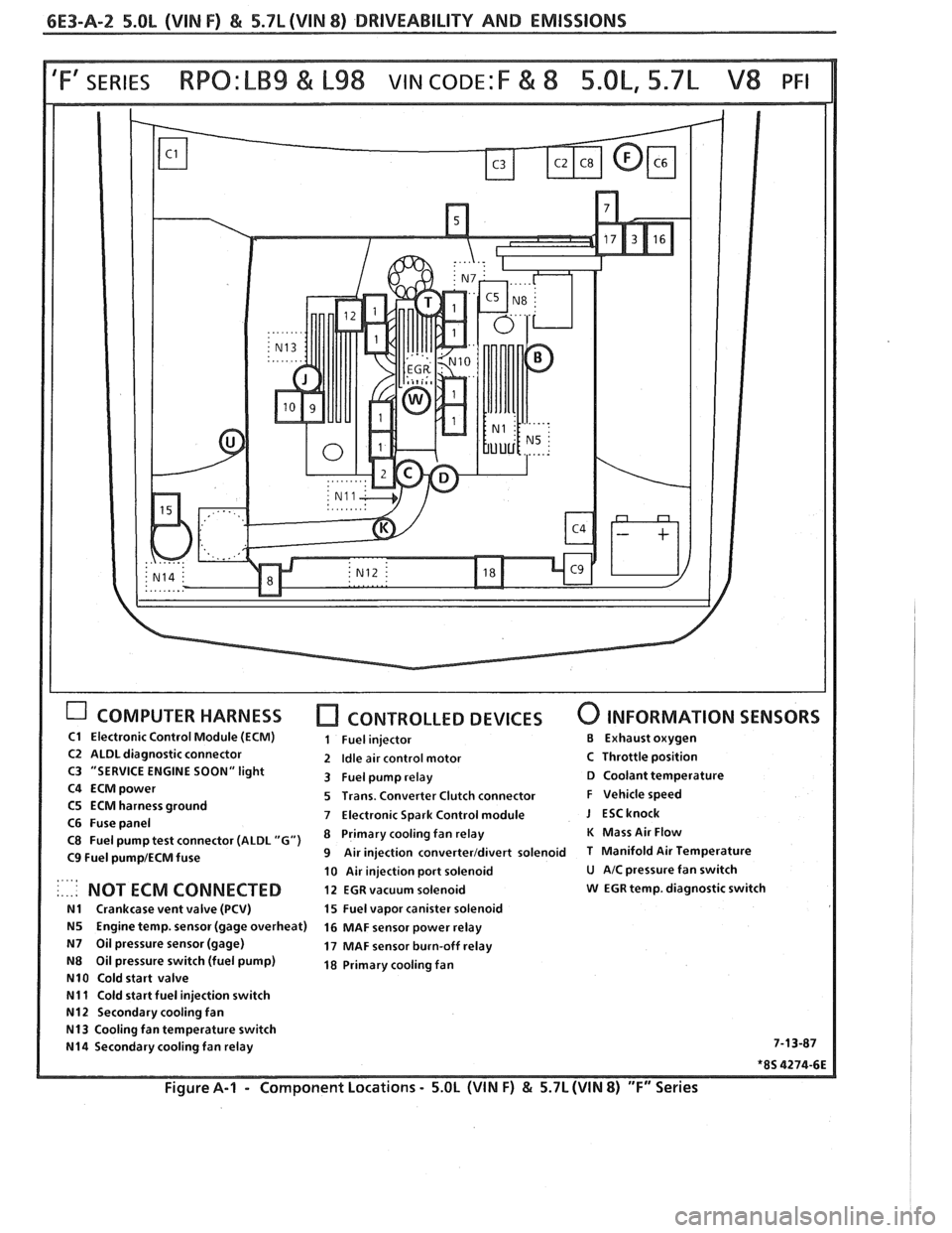
Figure A-I - Component
Locations - 5.OL (WIN F) & 5.7L (WIN 8) "F" Series